Table of Contents
Introduction
I’ve recently explored various simple user interfacing techniques and noticed that my small infrared Sony camera remote control looked ideal! It has a good amount of buttons for an interface, without all the clutter that is on TV remotes. It would be interesting to try it out with a Pi Pico.
This blog post could be handy for photographers who wish to use their existing remote controls for new purposes or for anyone who wishes to control their Pi Pico projects with a small remote keypad. Incidentally, it was later discovered that the information in this blog post is compatible with nearly every Sony remote control. It is not just limited to camera remote controls.
Finally, this blog might also be helpful for anyone wishing to discover the Pi Pico’s Programmable Input/Output (PIO) core along with me. If you’re not interested in that, you can skip it all and just use the code!
If you wish to play along, all you need is a Pi Pico, a cheap IR receiver module, plus (almost) any Sony remote control.

This blog doesn’t contain a complete guide to PIO, but nevertheless, enough is covered to make a completely usable app. I figured it could sometimes be more accessible to learn a language by just trying it for an actual task, and I hope it is explained in a reasonably easy-to-follow way.
SONY SONY SONY
My hands are clean; I didn’t actually touch a single Sony product to perform the reverse-engineering; I used a JJC brand remote control from Amazon, that happens to be compatible with Sony cameras.
Regardless, just in case any manufacturer has problems with the reverse-engineered information (although it is widely disseminated by others all over the Internet anyway, for example here), nevertheless, I’m referring to the protocol throughout this blog post as the SNY protocol and we won’t need to mention the name Sony ever again, beyond this introduction.
Arduino Library vs. PIO Core
There is an Arduino library that should work, but I didn’t want to use it because I wanted to be able to easily insert IR receiver functionality into a larger body of code that in any case was not using the Arduino environment. I was using the C/C++ SDK for the Pi Pico. It would be nice to attempt to use the Pi Pico’s Programmable Input/Output (PIO) block! It is described in more detail in the RP2040 PDF datasheet, in the PIO chapter.
The PIO is a small on-chip processor that can run simultaneously while the ARM cores are running and uses first-in-first-out (FIFO) interfaces for pushing and pulling data between the ARM core and the PIO core. Since the cores run simultaneously, there would be effectively zero overhead for existing applications using the ARM cores. In addition, the PIO works with MicroPython. By using the PIO, in one fell swoop, both C/C++ and MicroPython-based projects can be supported.
The downside, of course, is that the code would not be portable since the PIO only exists on the RP2040 chip. Another downside is that I would actually need to learn to use the PIO – it was new to me. After experimenting with it briefly, it was clear that programming the PIO is pretty much like programming in assembler language for old microcontrollers in that there are not a lot of instructions, nor is there much program space, and so some creativity would be needed.
The Pi Pico source repository actually contains an IR receiver example, but it is for remote controls that send in a specific format called NEC code. I could be mistaken but it seems NEC remote controls are not all that popular in homes. In the words of Jeff Bridges, this will not stand! It was time to try to learn how to use PIO a little bit, and see how to get SNY remote controls to function. This resultant blog post shows how to interface with such remote controls successfully.
Infra-Red Sensor
There are many three-pin infrared sensors that detect 38 kHz modulated light. Almost every TV set contains one. Nearly all of these sensors output a logic level 1 when there is no modulated light detected and output level 0 when the light is present. I used a part called VS1838B, but you could use any similar sensor. Reverse engineering is easy with such a sensor connected to an oscilloscope. The protocol detail is described next!
Protocol Described
The diagram below shows the data that is output from a typical IR receiver module when a button is pressed on the remote control. The precise timings vary a fair amount; for instance, the 600 us period could be in the range of 550-650 usec.

The actual protocol is simple; the output from the IR receiver idles high and then goes low for 2.4 msec when the button on the transmitter is pressed. Next, 20 bits are output, each one beginning with a 600 usec high pulse followed by either a 1.2 msec or a 600 usec pulse, representing binary 1 or binary 0 respectively. In summary, for all the 20 transmitted bits, the positive pulses are a fixed width of 600 usec, and the negative pulses are of either 600 usec or 1.2msec.
The NEC protocol on the other hand, behaves in an opposite manner, with fixed negative pulses. The timings are different too, and 32 bits are transmitted compared to the 20 bits in the SNY protocol. The NEC protocol sends a different value if the button is held down by the user, whereas the SNY protocol needs an alternate method to detect such a thing.
The screenshot below shows a SNY protocol capture when the ‘up’ button is pressed in the 5-button cluster on the remote control.
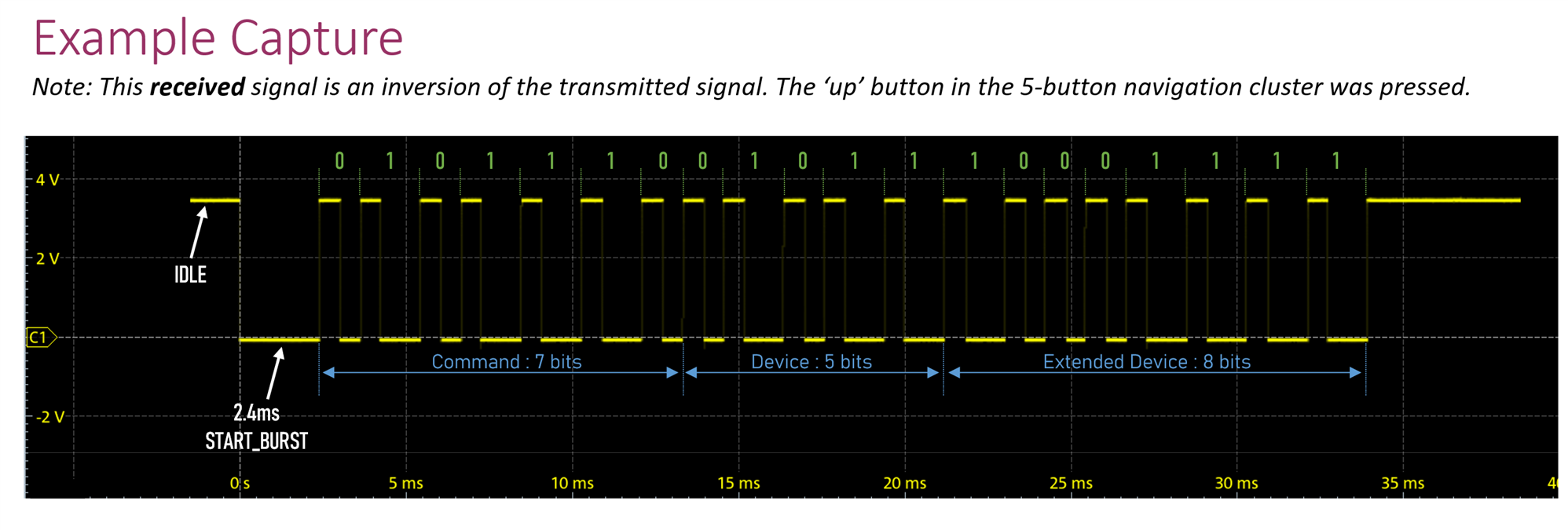
The 20 bits are split up into three fields, called Command, Device and Extended Device. The ordering for each field is least-significant bit first. So, in the screenshot above, the field values are:
Command: 58 decimal (0111010 binary)
Device: 26 decimal (11010 binary)
Extended Device: 241 decimal (11110001 binary)
Various websites tend to concatenate the Device and Extended Device fields to a single device string with decimal point separator. It would be 26.241 in this example. Thus, a 26.241 compatible device would be compatible with the remote control that was used in the example, and the code 58 for that device represents the up button.
PIO Coding Strategy
When working with the PIO, it is critical to sketch out what you’re trying to achieve accurately. I got nowhere until it was clear in my head, and on paper, how the protocol would be decoded.
The protocol was split into two pieces.
1. Determining when the Button is Pressed
The first part of the protocol was to determine when the remote control button was pressed, which caused the sensor output to go low for 2.4 msec. I decided that I wanted to detect when the IDLE state existed for a long time because that would indicate if the user had just pressed the button, as opposed to holding down the button.
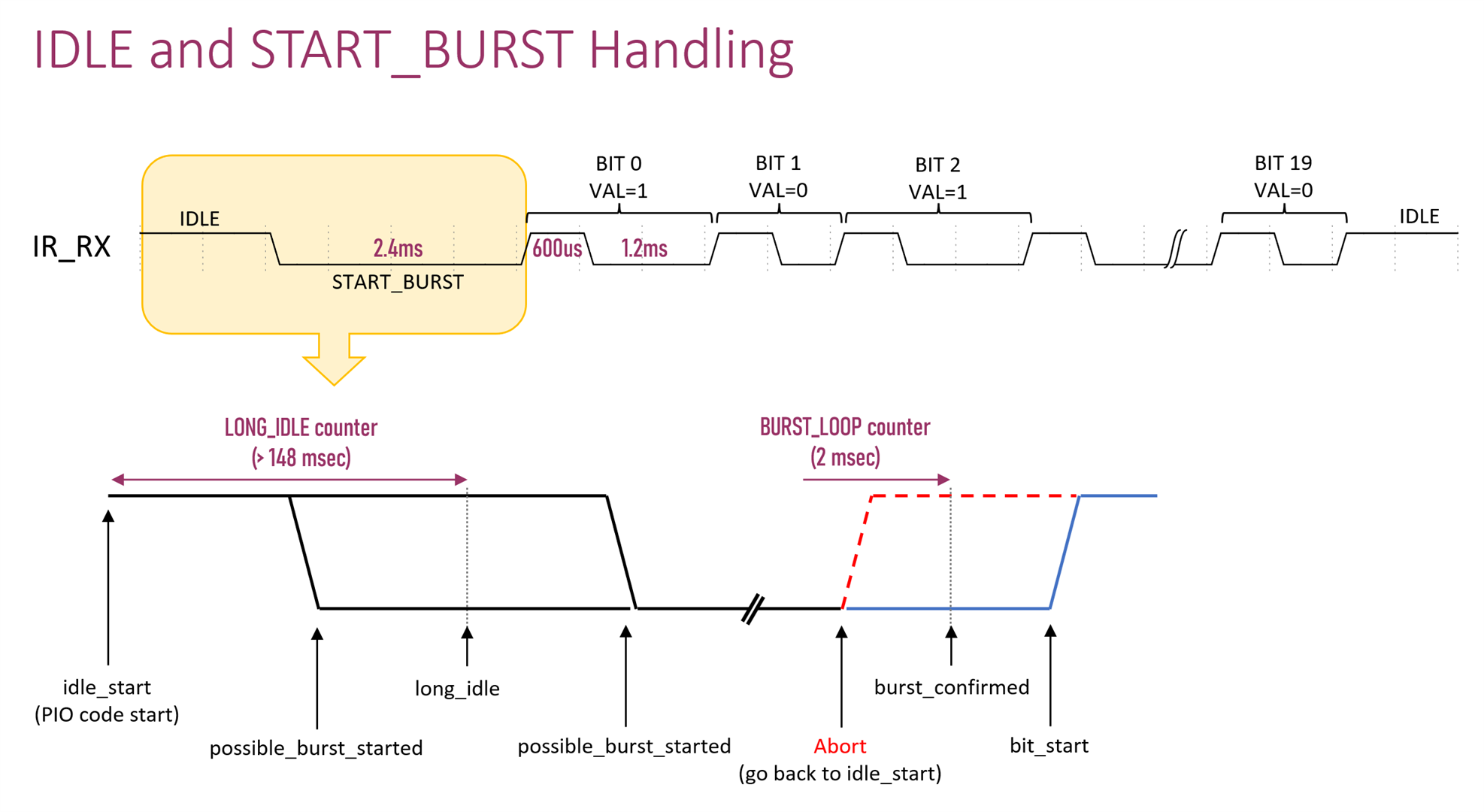
The various points of interest were all annotated with descriptive names, which would be present in the PIO code.
Here is what the code looks like, that implements that diagram. It is described step-by-step below.
(Note: the colorful screenshot is to aid readability but if you wish to see the actual text code, click here).
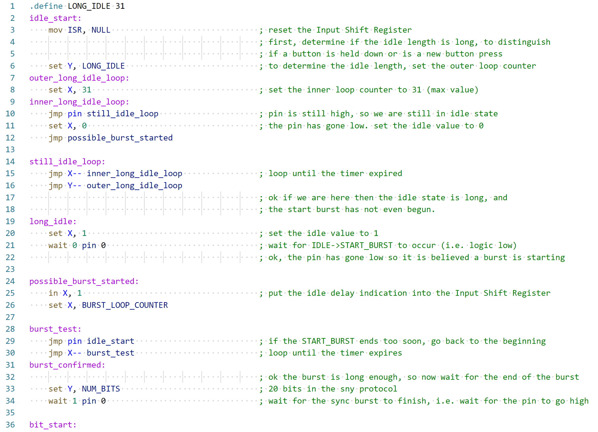
X and Y are effectively variables (they are registers). They can easily contain values up to 31 (they can contain higher values but set in an indirect way), so the LONG_IDLE is really a delay with another delay inside, to reach the 148 msec period; that’s what the outer_long_idle_loop and inner_long_idle_loop are for.
The wait 0 pin 0 command simply waits for a low voltage to appear on the pin reference 0. The in X,1 command is interesting; it will place one bit from the X register into a shift register that can be read from the C code outside of the PIO core. The aim of the code is to place the idle delay status (whether there was a long idle delay or not) as a single bit, into the 32-bit wide shift register. Ultimately, the 32-bits of the shift register will contain the idle delay status bit, plus 20 bits of remote control code, and they will all be read as a single 32-bit unsigned integer (with some spare bits padding) in the C code.
The jmp X-- and jmp Y-- commands are conditional jumps. They will jump if the value in X or Y is zero respectively. After determining the condition, the X or Y value is decreased by 1. The command is perfect for implementing a for loop, until the X or Y variable (register) reaches zero.
That’s all there is to the first part of the protocol!
2. Reading in the Bits
As mentioned earlier, there are 20 bits to read. The PIO block provides a command that can wait indefinitely for a pin to be high or low. The strategy I used for bit reading, was to only use such a wait command for waiting for high values, and specifically never for waiting for low values. The reason is, I didn’t want the PIO to end up in an accidental state where the code may be expecting further bits but the IR sensor has defaulted to the high idle state. I’d rather wait for high values so that even if things go wrong, it recovers quickly.
A single bit consists of a fixed 600 usec high pulse, followed by either 600 usec or 1200 usec (1.2 msec) low pulse, which indicates a bit value of 0 or 1 respectively. The diagram shows that there is a window in which if the pin goes high, then it means that the bit value is zero. If the pin does not go high during that window, then the bit value is 1.
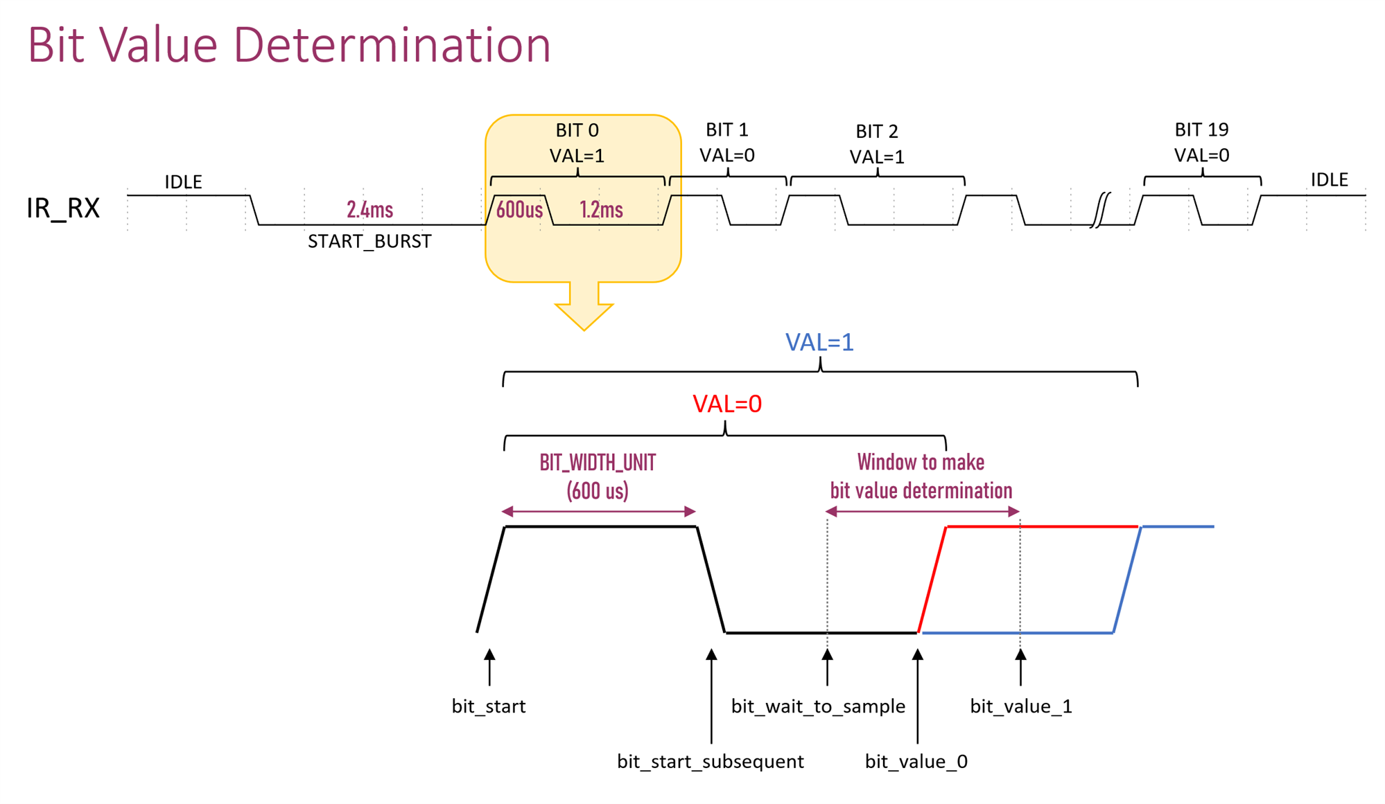
Here is the PIO code that implements the diagram:
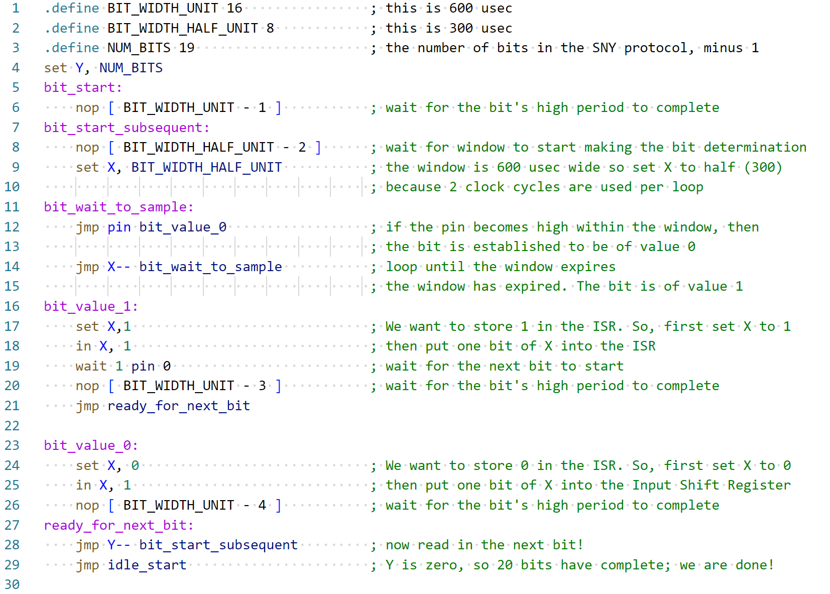
In the code above, the nop command simply delays for a little while. Since the command itself takes up one clock cycle, if a delay of n is required, then the command syntax is nop [ n -1 ]. Each instruction takes one clock cycle, and the code requires subtraction of the number of commands that are required to be part of any delay period. The rest of the code above uses similar commands as before, so hopefully it should be understandable in conjunction with the diagram.
Adding the PIO Code to C/C++ Code
As mentioned, the PIO code runs independently on the PIO core within the RP2040 chip. The PIO code is all saved into a file with a .pio suffix, and the RP2040 C/C++ software development kit (SDK) will call the PIO assembler, which will generate the machine instructions within a C array.

A small amount of glue code is used to store the instructions in the C array ready for execution by the PIO, along with a small amount of setup, and then the PIO can be instructed to run. None of this code needs to be written from scratch, since there are plenty of existing examples for the SDK.
What’s more of interest is how the coded functionality is actually used from the C code, i.e. how the interaction between the ARM core and the PIO core can be achieved.
The C main() function just needs to call two functions. The first function sny_ir_rx_init is used to set up the PIO and run it, as described above.
PIO pio = pio0int ir_state_machine = sny_ir_rx_init(pio, gpio_number);
Then, whenever it is desired to see if the user has pressed a button on the remote control, the following function is called:
if (!pio_sm_is_rx_fifo_empty(pio, ir_state_machine)) { uint32_t rx_frame = pio_sm_get(pio, ir_state_machine);}
The 32-bit unsigned integer rx_frame contains the idle length indication bit, plus the 20 bits received from the remote control, and the remainer 11 bits are unused.
I wrote a simple function to decode the 21 bits and print out the device and command details. The demo code loops repeatedly, printing out the received data to the serial console.
Here is example output when the up button is pressed; it displays the raw 32-bit contents of rx_frame, and the decoded device value and command value:
rx 0xf1d3a800: 26.241, command=58 repeat 0xf1d3a000: 26.241, command=58 repeat 0xf1d3a000: 26.241, command=58 repeat 0xf1d3a000: 26.241, command=58 repeat 0xf1d3a000: 26.241, command=58 repeat 0xf1d3a000: 26.241, command=58
Using PIO with MicroPython
MicroPython uses functions in place of each machine instruction to program up the PIO. It’s pretty simple to use, but of course, each PIO instruction needs to be translated into the function call name. It doesn’t take long to translate manually because PIO programs are not very long.
Here is the same PIO code as before, but this time in MicroPython:

As you can see, the code is identical, except that function calls were used in place of the machine instructions. Note that the first line in the screenshot above (beginning with @asm_pio) is important; it is a Python decorator that passes your PIO code function into a function that will perform the actual assembly of the instructions.
The PIO code is run from MicroPython using the following commands:
from machine import Pinfrom rp2 import asm_pio, PIO, StateMachineir_pin = Pin(15, Pin.IN, Pin.PULL_UP)sm = StateMachine(0, sny_ir_rx, freq=26667, in_base=ir_pin, jmp_pin=ir_pin)sm.active(1)
In the commands above, the clock rate is set to 37.5 usec by specifying a frequency of 26667 Hz.
The FIFO populated by the PIO code can be read at any time using the following command:
if sm.fifo() > 0: frame = sm.get()
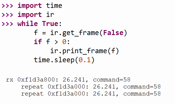
I wrote a simple function to decode the 32-bit integer as with the earlier C code, and saved the entire file as ir.py.
This was how the code was run and the output that occurred when the up button was pressed:
Putting it all Together: Servo Demo
As a quick demo, I added a servo to the Pi Pico and wrote a few lines of Python code to detect the left/right buttons on the camera remote control in order to rotate the servo or to center-ize it when the center button is pressed. It’s a trivial example, but it at least shows how the IR code can be used. The code is on GitHub.

Summary
The Pi Pico’s Programmable Input/Output (PIO) cores can be useful problem-solvers. In this blog post, a PIO core was used to implement a protocol that would have been annoying to run in the background on the main core, even though it is not a particularly fast protocol that was chosen.
By offloading to the PIO, one can more easily drop the functionality into existing C/C++ projects running on the Pi Pico, and as a bonus, the identical PIO code will work equally well with MicroPython since the PIO code execution is pretty much independent of what goes on in the ARM cores. It is a convenient way of getting fast or accurate timed protocols working directly with MicroPython.
A particular mode of thinking is needed when working with the PIO because not all instructions have complete symmetry with the parameters they accept, and there are limitations with code size, too. However, for the very low-level portion of protocols, it can be advantageous, although, due to the limitations mentioned, you will most likely need to do some pre- or post-processing of the data formats in C/C++ or Python before pushing or pulling data from the FIFOs that the PIO is connected to.
When working with the PIO, I’d strongly recommend sketching in detail what you’re trying to achieve and annotating all points of interest in the protocol you’re implementing (and adding to your code a lot of comments!).
As another tip, it is highly recommended to pull out the oscilloscope and be 100% sure about the protocol that you're implementing (and ensure any hardware developer has confirmed if inputs or outputs have active high or active low logic), because any subsequent changes will significantly alter the PIO code, due to the incomplete symmetry mentioned earlier.
The code that was developed works fine with most remote controls compatible with the SNY protocol.
Thanks for reading!
