element14 Community
element14 Community
    Register Log In
  • Site
  • Search
  • Log In Register
  • Community Hub
    Community Hub
    • What's New on element14
    • Feedback and Support
    • Benefits of Membership
    • Personal Blogs
    • Members Area
    • Achievement Levels
  • Learn
    Learn
    • Ask an Expert
    • eBooks
    • element14 presents
    • Learning Center
    • Tech Spotlight
    • STEM Academy
    • Webinars, Training and Events
    • Learning Groups
  • Technologies
    Technologies
    • 3D Printing
    • FPGA
    • Industrial Automation
    • Internet of Things
    • Power & Energy
    • Sensors
    • Technology Groups
  • Challenges & Projects
    Challenges & Projects
    • Design Challenges
    • element14 presents Projects
    • Project14
    • Arduino Projects
    • Raspberry Pi Projects
    • Project Groups
  • Products
    Products
    • Arduino
    • Avnet & Tria Boards Community
    • Dev Tools
    • Manufacturers
    • Multicomp Pro
    • Product Groups
    • Raspberry Pi
    • RoadTests & Reviews
  • About Us
  • Store
    Store
    • Visit Your Store
    • Choose another store...
      • Europe
      •  Austria (German)
      •  Belgium (Dutch, French)
      •  Bulgaria (Bulgarian)
      •  Czech Republic (Czech)
      •  Denmark (Danish)
      •  Estonia (Estonian)
      •  Finland (Finnish)
      •  France (French)
      •  Germany (German)
      •  Hungary (Hungarian)
      •  Ireland
      •  Israel
      •  Italy (Italian)
      •  Latvia (Latvian)
      •  
      •  Lithuania (Lithuanian)
      •  Netherlands (Dutch)
      •  Norway (Norwegian)
      •  Poland (Polish)
      •  Portugal (Portuguese)
      •  Romania (Romanian)
      •  Russia (Russian)
      •  Slovakia (Slovak)
      •  Slovenia (Slovenian)
      •  Spain (Spanish)
      •  Sweden (Swedish)
      •  Switzerland(German, French)
      •  Turkey (Turkish)
      •  United Kingdom
      • Asia Pacific
      •  Australia
      •  China
      •  Hong Kong
      •  India
      • Japan
      •  Korea (Korean)
      •  Malaysia
      •  New Zealand
      •  Philippines
      •  Singapore
      •  Taiwan
      •  Thailand (Thai)
      • Vietnam
      • Americas
      •  Brazil (Portuguese)
      •  Canada
      •  Mexico (Spanish)
      •  United States
      Can't find the country/region you're looking for? Visit our export site or find a local distributor.
  • Translate
  • Profile
  • Settings
Raspberry Pi Projects
  • Products
  • Raspberry Pi
  • Raspberry Pi Projects
  • More
  • Cancel
Raspberry Pi Projects
Blog Ras Pi Gaming Table
  • Blog
  • Documents
  • Events
  • Polls
  • Members
  • Mentions
  • Sub-Groups
  • Tags
  • More
  • Cancel
  • New
Join Raspberry Pi Projects to participate - click to join for free!
  • Share
  • More
  • Cancel
Group Actions
  • Group RSS
  • More
  • Cancel
Engagement
  • Author Author: mconners
  • Date Created: 8 Mar 2016 10:01 PM Date Created
  • Views 2980 views
  • Likes 9 likes
  • Comments 22 comments
  • retro gaming
  • rpibeginner
  • raspberry pi
  • retropie
  • ras_pi
  • ras pi 3
  • raspberry_pi_projects
  • arduino
Related
Recommended

Ras Pi Gaming Table

mconners
mconners
8 Mar 2016

This will be my interpretation of the Ras Pi gaming table as highlighted here PIK3A: The Raspberry Pi 3 IKEA Retro Gaming Table posted by spannerspencer.


I have most of the parts on hand, but I am still waiting for a key component, the screen. I had one, I thought, but it turned out to be inoperative.


So I ordered one from ebay and expect to have it pretty soon.


I'm pretty much sticking to the plan as described, with a few minor changes.


image


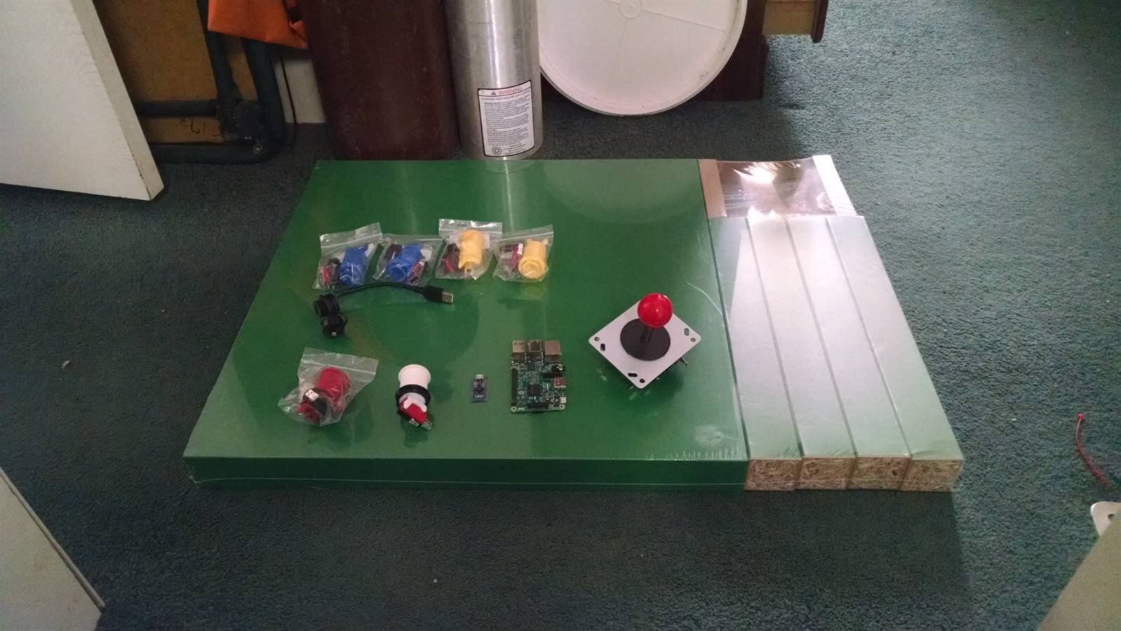
There is what I have so far.


Ikea Lack Table

6 Arcade Buttons

1 Arcade Joystick

USB Jack

Ras Pi 3

Arduino Micro Compatible board


I switched up the table color to green, and one of the buttons to red.


Also the little PCB next to the Pi 3 is an arduino micro clone. It is important that the microcontroller on the board is a 32U4 as is found on the leonardo, because that one supports the keyboard emulation.


The Microcontroller Board

I guess I can get into why I chose the microcontroller board that I did. I have an Arduino Leonardo, but I chose not to use it. The main reason for this was the size and the fact that the headers were already attached.

I purchased a board where the headers were not soldered on so I could ensure that the controllers were firmly attached. As I mentioned above I needed something with a 32U4 and the OSOYOO Micro AT mega fit the bill. It's not a direct copy of the Arduino Micro, it has a few less IO ports, but it was adequate to do the job. I'm fortunate to have a logic analyzer, a Digilent Analog Discovery, that I purchased when I took the EdX class Embedded Systems : Shape the World that they advertise here on E14, got it at the student discount, so it was a good deal, anyway I was able to use it to ensure that the pins I needed were mapped correctly, because the board layout didn't match anything that I had seen. I could have wired up an LED and a resistor on a breadboard and accomplished the same thing, but this was easier, and it motivated me to solder up a batch of clip on probes that I bought a while ago. I purchased the board on amazon and they were about $8 each, shipped.


The Buttons and Joystick

The buttons and joystick were also purchased on amazon. I know MCM and CPC sell them, but I'm a cheap old guy so I managed to get them for ~$25. That was well worth it. They seem like quality parts and I'm happy with the purchase.


The Table

I live in the country. The nearest city is about 25 miles away. I live on 50 acres and I like it that way. The nearest IKEA is about 100 miles away. So, my old friend Jeff Bezos provided again. I paid $20 for a $10 table, but I didn't have to leave the house. I chose green instead of red because I like green better. But i did swap out the green button that Spencer used for a red one to keep the same color scheme.


The Pi

I have a Pi 3, but I also have a Pi2, so I don't know which I'm going to use yet. I am running retropie on a Pi2 right now, so I know it's up to the task. I hate to tie up my newly acquired Pi3 for this. I have a bunch of WiFi dongles that I bought for cheap, so I may go with the Pi2. We'll see as I get closer to build time.


The USB Jack

I don't know why, but when I saw this as part of the original build, I got really excited. It was not listed on the BOM so I had to ask for the part number.

MULTICOMP - 2UB3001-W05101 - ADAPTER, USB TYPE A, JACK - PLUG | CPC UK

2UB3001-W05101 - MULTICOMP - CABLE, USB A JACK TO USB A PLUG, 100MM, BLACK | Newark element14

I love the through hole mounting and the dust cap. This will give you access to one of the Pi's USB ports, this way you can add a keyboard, or a hub, or whatever. Since this thing will really be running the full RetroPie distro, you can add NES, SNES, or Playstation controllers if you decide to play with any of the other available emulators.


Got the Buttons Installed

I managed to make the cutouts and get the buttons installed. Now to wire it all up.


image


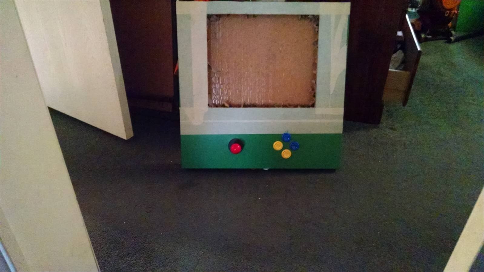
I got all the buttons wired. It gets crowded in there. I tested it out by connecting to an external monitor. All the buttons seemed to work.

My Arduino Micro style board worked great.


I'll take some more pics and post them soon.


Well, it's together and functional. I ended up going with the Ras Pi 3, and I paired a bluetooth keyboard with it to give me a little more control over the machine.
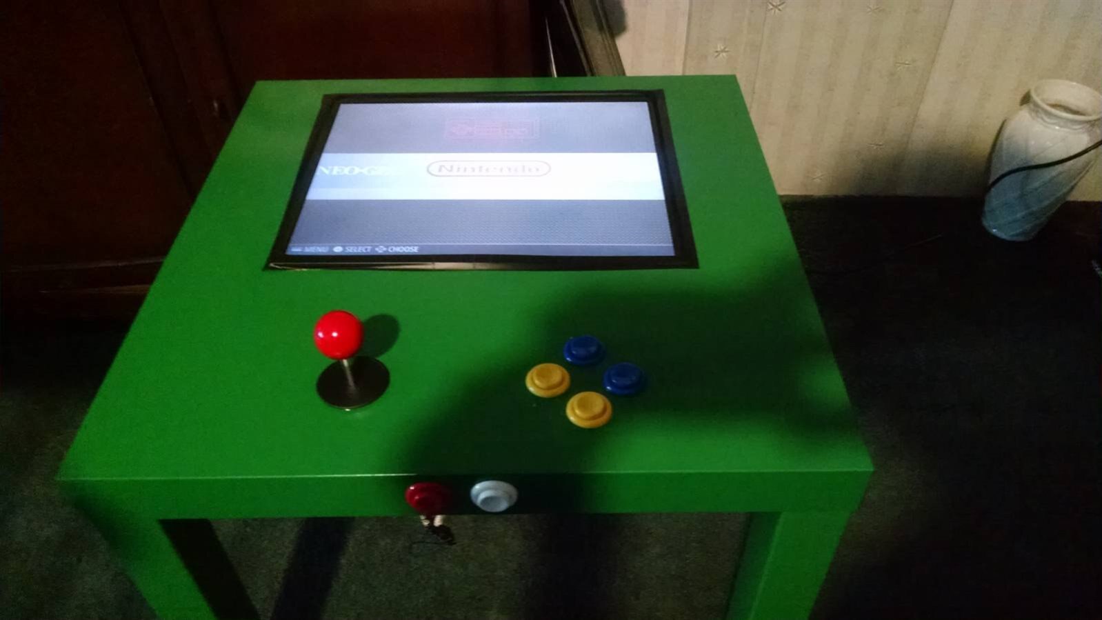
 

image


Mostly done!!!


Summary & Lessons Learned


Now that this project is mostly complete, I have to say this was one of the most rewarding Ras Pi projects I have embarked upon. My kids and I have had a blast playing with this thing.

There are, however, a few things I would do differently if I were to duplicate this effort in the future


One, I would go with bluetooth speakers. Even if going with an earlier version of the Pi. A bluetooth dongle is an inexpensive addition, but having it built into the Pi3 is a plus, it would be more convenient to add a bluetooth soundbar of some type to add sound rather than drill holes and mount the speakers in the table.


Two, I would add an hdmi extension to be able to connect the device to another monitor if desired.


Three, I was only able to use 16 gauge wire to attach the buttons. This was what was available at the local hardware store, I would go for 20 gauge wires in a second build.


Four, I would probably add a few more buttons, just for a bit more flexibility.


I still haven't decided if I will put an acrylic top over the screen or not.


All in all, though, this was an awesome project. Only the future will tell what derivative works will grow out of this.

  • Sign in to reply

Top Comments

  • spannerspencer
    spannerspencer over 9 years ago in reply to bombo +4
    Hey man! I can't get to the underneath to take a photo, as it's all actually inside the table. But, what I did when I dismantled the monitor was insulate the thin PCB with the buttons on it, and then taped…
  • mconners
    mconners over 9 years ago in reply to spannerspencer +3
    Thanks, Spanner. I have to admit, the red really caught my eye when I first saw yours, but I felt the green still captured the "Playskool" spirit, but the white ones and black ones that others have built…
  • bombo
    bombo over 9 years ago +3
    Great Job. Loving this project. Parts are almost in and can't wait to get started!
  • bombo
    bombo over 9 years ago in reply to spannerspencer

    Great Tip!

    Will make sure I do that.

    • Cancel
    • Vote Up 0 Vote Down
    • Sign in to reply
    • More
    • Cancel
  • spannerspencer
    spannerspencer over 9 years ago in reply to bombo

    Hey man! I can't get to the underneath to take a photo, as it's all actually inside the table.


    But, what I did when I dismantled the monitor was insulate the thin PCB with the buttons on it, and then taped it to the back of the chassis. Nothing too fancy (in fact, quite rough!), but it keeps it safe and out of the way.


    One top tip: Turn the brightness and contrast right up before installing the monitor. The angle you'll be looking at it from isn't ideal for LCDs, so ramping up the brightness and contrast really helps with that. And it's a pain to do after it's been set into the table top.

    • Cancel
    • Vote Up +4 Vote Down
    • Sign in to reply
    • More
    • Cancel
  • bombo
    bombo over 9 years ago

    Last question..I hope lol.

    How did you guys mount the power button for monitor?

    Are you able to take a picture of the bottom of the table?

    I know it is congested in there and may be hard to see.


    Thanks again

    • Cancel
    • Vote Up 0 Vote Down
    • Sign in to reply
    • More
    • Cancel
  • bombo
    bombo over 9 years ago in reply to spannerspencer

    Thank you Gentleman!!

    • Cancel
    • Vote Up 0 Vote Down
    • Sign in to reply
    • More
    • Cancel
  • spannerspencer
    spannerspencer over 9 years ago in reply to mconners

    Yeah, if you can find the ones with the leaf switches built in, they fit the IKEA tables better. Although I do like these with the microswitches better, the other kind (I used these ARCADE STYLE PUSH BUTTON | Premier Farnell CPC UK ) do fit inside the tables better.

    • Cancel
    • Vote Up 0 Vote Down
    • Sign in to reply
    • More
    • Cancel
>
element14 Community

element14 is the first online community specifically for engineers. Connect with your peers and get expert answers to your questions.

  • Members
  • Learn
  • Technologies
  • Challenges & Projects
  • Products
  • Store
  • About Us
  • Feedback & Support
  • FAQs
  • Terms of Use
  • Privacy Policy
  • Legal and Copyright Notices
  • Sitemap
  • Cookies

An Avnet Company © 2025 Premier Farnell Limited. All Rights Reserved.

Premier Farnell Ltd, registered in England and Wales (no 00876412), registered office: Farnell House, Forge Lane, Leeds LS12 2NE.

ICP 备案号 10220084.

Follow element14

  • X
  • Facebook
  • linkedin
  • YouTube