element14 Community
element14 Community
    Register Log In
  • Site
  • Search
  • Log In Register
  • Community Hub
    Community Hub
    • What's New on element14
    • Feedback and Support
    • Benefits of Membership
    • Personal Blogs
    • Members Area
    • Achievement Levels
  • Learn
    Learn
    • Ask an Expert
    • eBooks
    • element14 presents
    • Learning Center
    • Tech Spotlight
    • STEM Academy
    • Webinars, Training and Events
    • Learning Groups
  • Technologies
    Technologies
    • 3D Printing
    • FPGA
    • Industrial Automation
    • Internet of Things
    • Power & Energy
    • Sensors
    • Technology Groups
  • Challenges & Projects
    Challenges & Projects
    • Design Challenges
    • element14 presents Projects
    • Project14
    • Arduino Projects
    • Raspberry Pi Projects
    • Project Groups
  • Products
    Products
    • Arduino
    • Avnet & Tria Boards Community
    • Dev Tools
    • Manufacturers
    • Multicomp Pro
    • Product Groups
    • Raspberry Pi
    • RoadTests & Reviews
  • About Us
  • Store
    Store
    • Visit Your Store
    • Choose another store...
      • Europe
      •  Austria (German)
      •  Belgium (Dutch, French)
      •  Bulgaria (Bulgarian)
      •  Czech Republic (Czech)
      •  Denmark (Danish)
      •  Estonia (Estonian)
      •  Finland (Finnish)
      •  France (French)
      •  Germany (German)
      •  Hungary (Hungarian)
      •  Ireland
      •  Israel
      •  Italy (Italian)
      •  Latvia (Latvian)
      •  
      •  Lithuania (Lithuanian)
      •  Netherlands (Dutch)
      •  Norway (Norwegian)
      •  Poland (Polish)
      •  Portugal (Portuguese)
      •  Romania (Romanian)
      •  Russia (Russian)
      •  Slovakia (Slovak)
      •  Slovenia (Slovenian)
      •  Spain (Spanish)
      •  Sweden (Swedish)
      •  Switzerland(German, French)
      •  Turkey (Turkish)
      •  United Kingdom
      • Asia Pacific
      •  Australia
      •  China
      •  Hong Kong
      •  India
      •  Korea (Korean)
      •  Malaysia
      •  New Zealand
      •  Philippines
      •  Singapore
      •  Taiwan
      •  Thailand (Thai)
      • Americas
      •  Brazil (Portuguese)
      •  Canada
      •  Mexico (Spanish)
      •  United States
      Can't find the country/region you're looking for? Visit our export site or find a local distributor.
  • Translate
  • Profile
  • Settings
Raspberry Pi Projects
  • Products
  • Raspberry Pi
  • Raspberry Pi Projects
  • More
  • Cancel
Raspberry Pi Projects
Blog Step by Step Build Trick or Trivia Halloween Candy Dispenser #2- Put together & LCD working
  • Blog
  • Documents
  • Events
  • Polls
  • Members
  • Mentions
  • Sub-Groups
  • Tags
  • More
  • Cancel
  • New
Join Raspberry Pi Projects to participate - click to join for free!
  • Share
  • More
  • Cancel
Group Actions
  • Group RSS
  • More
  • Cancel
Engagement
  • Author Author: cmelement14
  • Date Created: 18 Oct 2015 10:08 PM Date Created
  • Views 461 views
  • Likes 3 likes
  • Comments 1 comment
  • raspberry_pi_projects
  • pumpkinpi2015
Related
Recommended

Step by Step Build Trick or Trivia Halloween Candy Dispenser #2- Put together & LCD working

cmelement14
cmelement14
18 Oct 2015

Following the previous blog Step by Step Build Trick or Trivia Halloween Candy Dispenser #1, I will start from configuring WiFi. I used a couple of links to help me set up Wifi: https://www.raspberrypi.org/documentation/configuration/wireless/wireless-cli.md and How-To: Add WiFi to the Raspberry Pi | Raspberry Pi HQ. Basically you need add a new network in /etc/wpa_supplicant/wpa_supplicant.conf file like this


network={
    ssid="your router ssid"
    psk="wifi password"
}


After configuring Wifi, I rebooted Pi 2 and unplugged the Ethernet cable. I opened my router's website and found the new IP address(e.g., 192.168.1.112) assigned to Pi's wifi interface. Then SSH to the Pi 2 using command

ssh pi@192.168.1.112


And Pi 2 accepted the connection as expected

$ ssh pi@192.168.1.112
pi@192.168.1.112's password: 
Linux raspberrypi 3.18.11-v7+ #781 SMP PREEMPT Tue Apr 21 18:07:59 BST 2015 armv7l

The programs included with the Debian GNU/Linux system are free software;
the exact distribution terms for each program are described in the
individual files in /usr/share/doc/*/copyright.

Debian GNU/Linux comes with ABSOLUTELY NO WARRANTY, to the extent
permitted by applicable law.
Last login: Sun Oct 18 13:37:31 2015 from lianhongs-air

NOTICE: the software on this Raspberry Pi has not been fully configured. Please run 'sudo raspi-config'


and Pi 2 had no abnormal behavior

image


After you have the network connection, you need make sure you have the latest Raspbian OS (you can download from https://www.raspberrypi.org/downloads/raspbian/) installed. Otherwise, you need run the following update and upgrade commands:

$sudo apt-get update
$sudo apt-get upgrade -y


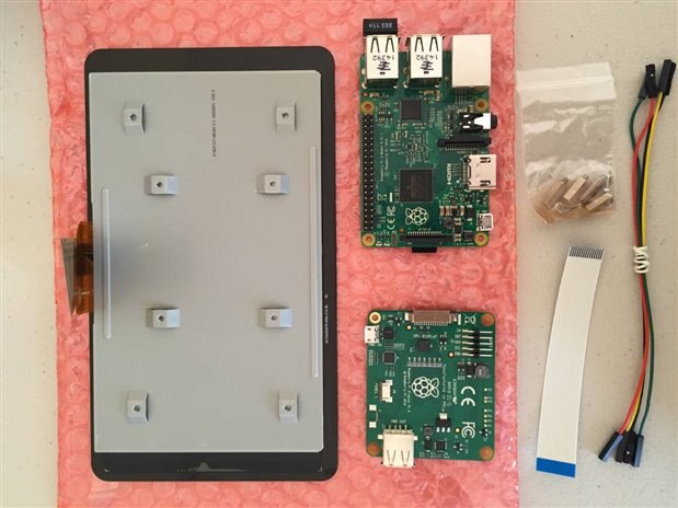
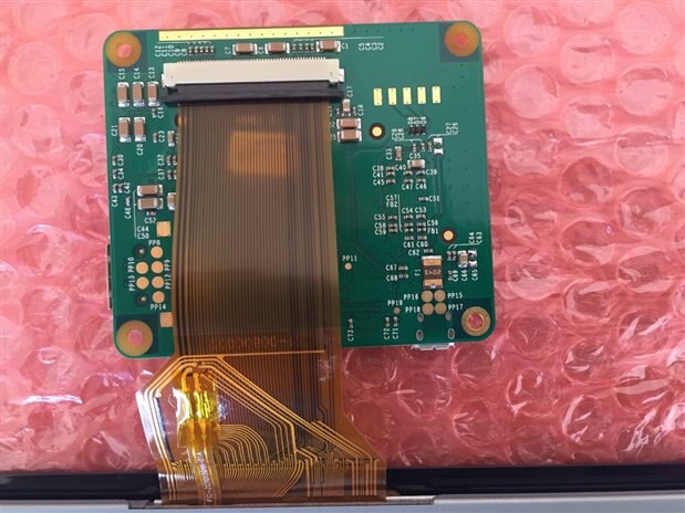
Now, it's the time to mount Pi 2 on the LCD panel. The picture below shows the parts to mount together.

image


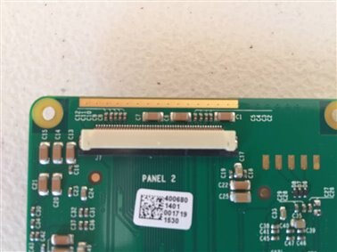
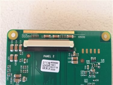
If you haven't used LCD flexi cable before, please note that the latch on the connector is usually closed when it arrives. You need open it before you insert the flexi cable into the connector as shown below. The first pic shows close state while the second shows it in open state. To open it, just pull the latch from the two ends simultaneously.

imageimage


Next insert the flexi cable to the connector on the LCD driver board through the bottom of the latch (shown below). After the cable is inserted, remember to close latches by pushing two ends back.

image


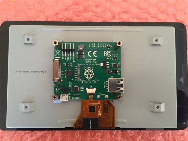
Then connector the other cable to the driver board as well. Also screw in the four standoffs as shown below.

image


Next, we connect driver board with the Pi 2. Please note that the flexi cable needs to insert into the connector through the top of the latch this time rather than through the bottom.

image


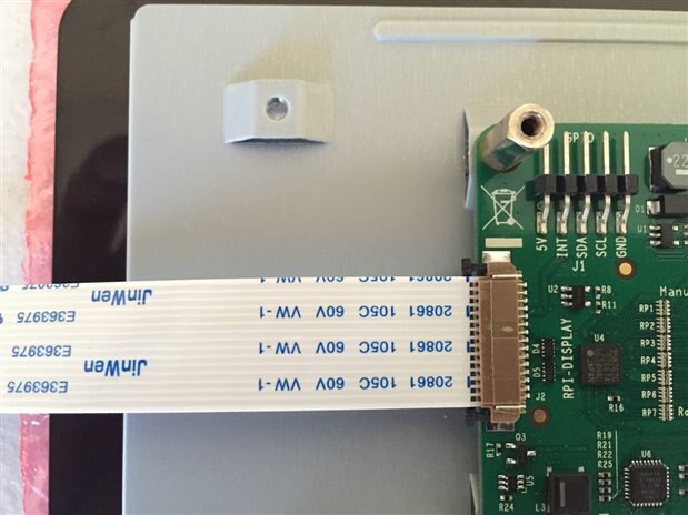
Next, connect the other end of the flexi cable to Pi 2's display port. Also connect two wires from the driver board to Pi 2's GPIO pin#2 & #6 as shown below.

image


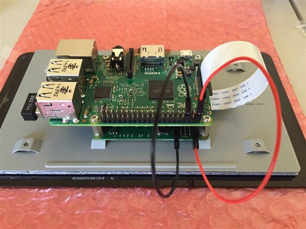
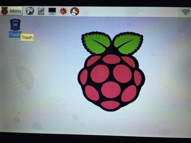
Now time to power up the Pi & LCD. You cannot use the power adapter came with the kit as described in my previous blog (Step by Step Build Trick or Trivia Halloween Candy Dispenser #1). You have to use a 5V, 2A adapter. If everything goes well so far, you should be able to see Desktop on the LCD display as shown below. I assume you have completed the OS configuration using command sudo rasp-config and configured the automatic startup of desktop.

image


In summary, I got wifi and LCD work in this blog. I will continue my work and stay tune for the next blog Step by Step Build Trick or Trivia Halloween Candy Dispenser #3.

  • Sign in to reply

Top Comments

  • DAB
    DAB over 10 years ago +2
    Nice detailed blog. You give me confidence that even I might get one of these displays working with my Rpi. DAB
  • DAB
    DAB over 10 years ago

    Nice detailed blog.


    You give me confidence that even I might get one of these displays working with my Rpi.


    DAB

    • Cancel
    • Vote Up +2 Vote Down
    • Sign in to reply
    • More
    • Cancel
element14 Community

element14 is the first online community specifically for engineers. Connect with your peers and get expert answers to your questions.

  • Members
  • Learn
  • Technologies
  • Challenges & Projects
  • Products
  • Store
  • About Us
  • Feedback & Support
  • FAQs
  • Terms of Use
  • Privacy Policy
  • Legal and Copyright Notices
  • Sitemap
  • Cookies

An Avnet Company © 2025 Premier Farnell Limited. All Rights Reserved.

Premier Farnell Ltd, registered in England and Wales (no 00876412), registered office: Farnell House, Forge Lane, Leeds LS12 2NE.

ICP 备案号 10220084.

Follow element14

  • X
  • Facebook
  • linkedin
  • YouTube