


Welcome back to the Trick or Trivia Blog. In this installment, I am going to cover the candy dispensing mechanical assembly, as well as the coding to get the servo up and running on the Raspberry Pi 2. Up until now, all of the parts needed to build this project were able to be purchased from Newark.com or MCM Electronics, but this portion will require a 3D printer or some handy inguinuity and minor skills with wood working equipment. I have included both the printable .STL files as well as the sketchup design files so that anyone following along at home can recreate, improve, or modify things to fit their needs.
When I came up with the concept of the Trick or Trivia candy dispenser, I spent hours trying to figure out the best way to autonomously dispense Halloween candy one piece at a time, and mocked up a few designs in sketchup. After a lot of thought, I came to the conclusion that the candy needed to be very compact and pretty uniform and consistent in size. It was also important that the candy be very tightly wrapped as loose packaging caused jams. I finally settled on Starburst candies as they fit all of the requirements. Starburst were actually my second choice, with Now & Later candies being my first. Unfortunately I could not find any of them locally, and know that Starburst are found throughout the US and abroad. Let’s get into the meat of things, and talk about the hardware needed for this project.
The Hardware
Below you will see a list of the hardware used to build out the candy dispenser portion of this project. In addition to these components, you will need the following tools: a soldering iron, solder, flush cutters, wire strippers, 12-inches or more of 3-conductor wire, 16 Gauge Galvanized Steel Wire (found at hobby stores), and a bag of Starburst candies.
Newark.com
Newark Part No. | Notes | Qty | Manufacturer / Description |
38Y646738Y6467 | RPi | 1 | RASPBERRY PI 2, MODEL B, |
38Y647038Y6470 | SD Card | 1 | RASPBERRY PI 8GB NOOBS MICRO SD CARD |
44W493244W4932 | PSU | 1 | POWER SUPPLY 5V, 1A |
06W104906W1049 | USB Cable | 1 | USB A PLUG TO MICRO USB B PLUG |
53W628553W6285 | WiFi Dongle | 1 | ADAFRUIT USB WIFI MODULE |
58K382758K3827 | Resistors | 1 | METAL FILM RESISTOR, 220 OHM, 250mW, 1% |
10M846410M8464 | General Purpose Diode | 1 | 1N40011N4001 Rectifier Diode 50 V 1 A |
34C109234C1092 | PSU Vreg | 1 | 7805 LINEAR VOLTAGE REGULATOR, 5V, TO-220-3 |
17F216517F2165 | PSU Filter Cap | 1 | CERAMIC CAPACITOR 0.1UF, 50V, X7R, 20% |
69K790769K7907 | PSU Filter Cap | 1 | ELECTROLYTIC CAPACITOR 100UF, 50V, 20%, |
14N941814N9418 | PSU LED | 1 | RED, T-1 3/4 (5MM) |
| 49Y171249Y1712 | 7-Inch Touch Screen | 1 | Raspberry Pi 7" Touch Screen Display |
| 66H746266H7462 | Strip Board | 1 | VECTOR ELECTRONICS-8022-PCB, Tracks(Strip Board) |
| 21M490921M4909 | Screw Terminal | 2 | MOLEX-39543-0002-TERMINAL BLOCK |
MCM Electronics
MCM Part No. | Notes | Qty | Manufacturer / Description |
Servo | 1 | Micro Servo |
3D Printing The Candy Dispenser Assembly
I chose to 3D print the parts for the candy dispenser simply because I have a few 3D Printers at my disposal at home, and could quickly design everything in Sketchup. If you do not have a 3D printer, you could easily build this assembly from wood or even foam core. The most important thing to remember is to leave enough clearance on all moving parts to negate any candy size anomalies.
Download all of the .STL files and the Sketchup design file from Thingiverse.com.
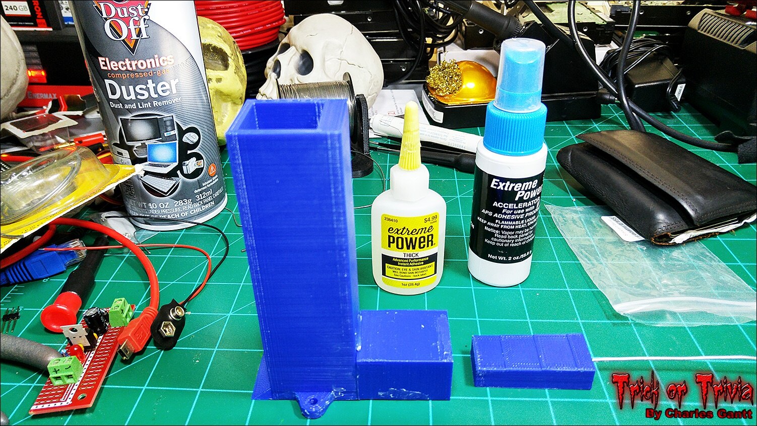
To keep this blog at a somewhat reasonable length, I am not going to post any images of the parts being 3D printed but as you can see from the image below, they print well at a 0.25mm layer height. I used Voltivo Excelfil PLA Filament as the printing medium as PLA is more food-safe than ABS. Since the candy is wrapped in wax-coated paper, PLA is fine to make the dispenser out of.

I mocked up the candy dispenser on a scrap box from a previous Newark order, and used hot glue to temporarily stick everything together. This was a very important step as I realized that the plunger tube was about 2mm taller than the magazine was despite being exactly the same in the sketchup file. I printed the tube again and the second try was perfect. I suspect a slicing error to be the cause of the first tubes difference. I apologize for the low-quality image, I simply got so wrapped up in getting this to work, that I forgot to take one, and had to use a screen cap from a video of everything working.
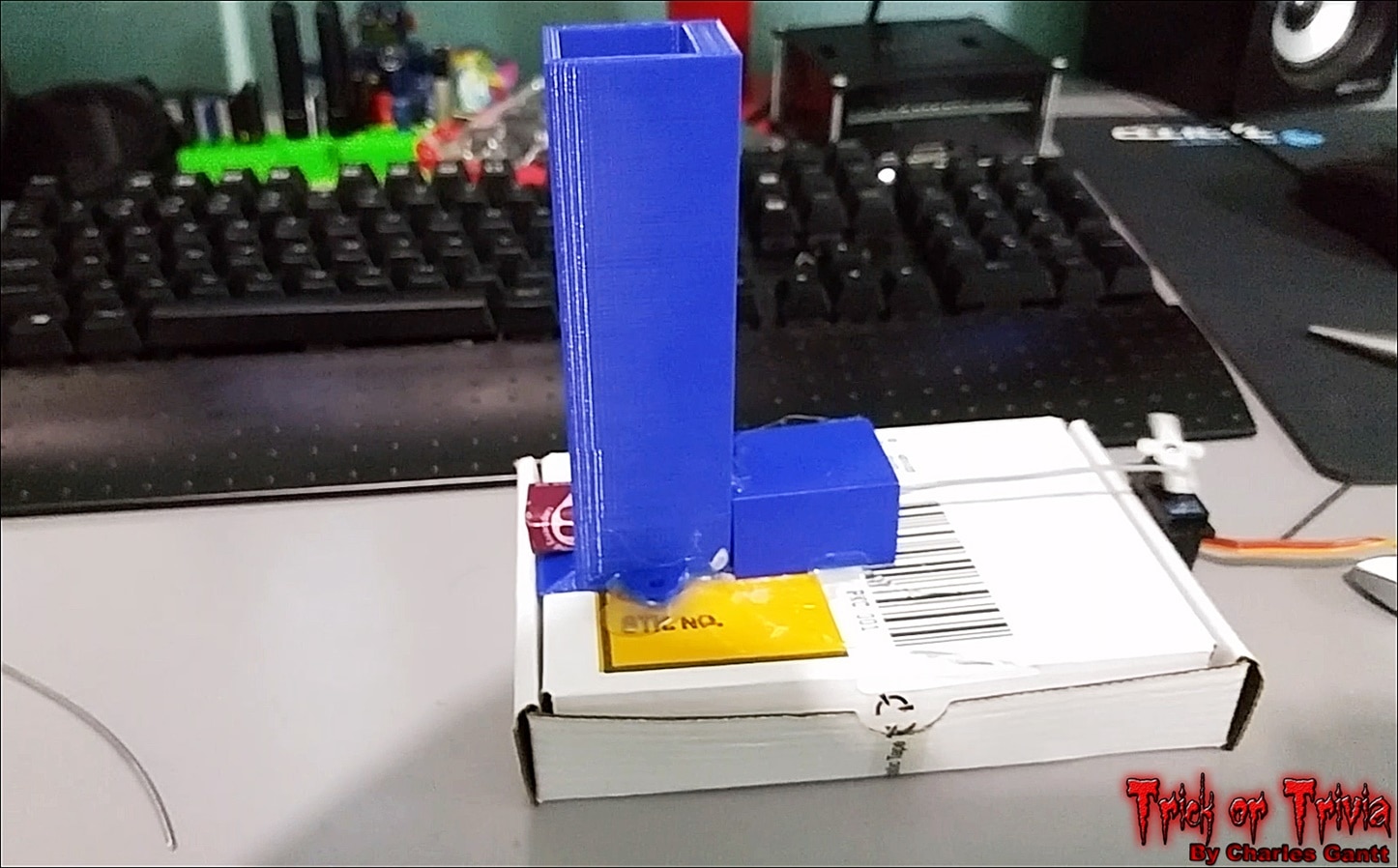
In the image above you can see that I have the servo mounted to the back of the box, with the push-rod made from the 16 gauge wire pushing the plunger into the tube. It took a little trial and error to get the length right, and to get the servo’s horn placed just right, so that it would push candy out and not bind on the return stroke.
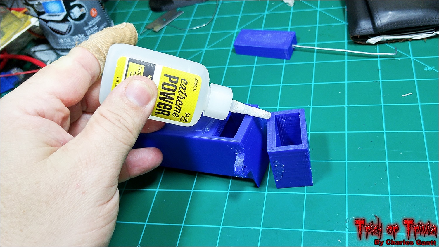
With everything lined up and secure, I tested the dispenser for over an hour until I was confident that everything would work fine. I then super glued the plunger tube to the candy magazine using a thick, gel-like super glue. If this were ABS plastic I would have solvent-welded it together using acetone instead.
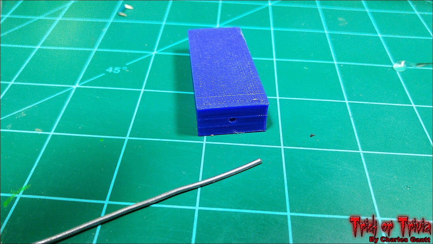
I then glued the steel rod into the plunger block using hot glue. I chose hot glue as it is easier to remove if I need to change its length.
With the easy part done, it was time to move on to getting the code for the servo working.
Wiring and Coding the Servo.
When designing the original kit for this project I listed a normal-sized hobby servo as I thought it’s extra power would be needed, but as it turns out, a smaller 9g servo works much better. This is due to the fact that the candy sometimes binds in the tube if it’s wrapper is coming loose, and when it binds, the bigger servo will actually bend the steel push rod. The 9g servo simply stalls out, preventing the rod from bending.
The servo I am using is a small 9g metal-gear servo from Hobby King’s Turnigy line, but the one listed in the parts list at the top of this post will work just as good. I also had issues trying to drive the original Tower Pro servo from the Raspberry Pi 2, even with a 6-volt, 5-amp power supply hooked to it. The smaller 9G servos worked just fine with the 5V power supply we will build later in this post.
The PIGPIO Library
To drive the servo and retain audio output I chose to install the pigpio library. Installing it is as easy as entering the following commands into the terminal one by one.
wget abyz.co.uk/rpi/pigpio/pigpio.zip
unzip pigpio.zip
cd PIGPIO
make
sudo make install
Then restart the Raspberry Pi with the following command.
sudo reboot
Once the Pi is back up and running, we need to start the pigpio module using the following command.
sudo pigpiod
This command will need to be ran every time the Raspberry Pi reboots. I simply added it to the crontab, just like we did with the command that plays the ambient audio on boot. In the event you need to stop the pigpio module, simply run the commands below. To find out more about what the pigpio module can do, check out its info-page.
sudo killall pigpiod
Servo Control Code
I chose the pigpio module because it not only allows the user to utilize all of the Raspberry Pi’s GPIO pins as PWM pins, but because it does not block audio like some of the other servo control solutions do. An added bonus is how easy it is to program servo control using Python with this library. Below is a breakdown of the servo code, followed by the full TrickOrTrivia code with the servo control integrated. As always, you can find the full code for this project at its Github repo.
First we need to import the time and pigpio libraries.
import time
import pigpio
Next we need to define which GPIO pin is connected to the servo.
servos = 4 #GPIO number
Now we need to initialize the pigpio library
pi = pigpio.pi()
This next block of code is the function that makes the candy dispenser’s plunger move back and forth to dispense three pieces of candy upon a correct answer. We are telling the servo to move hard right with a pulsewidth of 2500, and then move a little more than 90 degrees left with a pulsewidth of 1300. We wait 0.5 seconds between each move. When finished, we turn the servo off by setting a pulse width of 0, and telling the pigpio module to stop. Finally we break out of this function.
def correct_servo ():
        while True:
            pi.set_servo_pulsewidth(servos, 2500)
            time.sleep(.5)


            pi.set_servo_pulsewidth(servos, 1300)
            time.sleep(.5)


            pi.set_servo_pulsewidth(servos, 2500)
            time.sleep(.5)


            pi.set_servo_pulsewidth(servos, 1300)
            time.sleep(.5)


            pi.set_servo_pulsewidth(servos, 2500)
            time.sleep(.5)


            pi.set_servo_pulsewidth(servos, 1300)
            time.sleep(.5)


            pi.set_servo_pulsewidth(servos, 0);
            pi.stop()
            break
The same code works for the incorrect answer, but only dispenses a single piece of candy.
def incorrect_servo ():
    while True:
        pi.set_servo_pulsewidth(servos, 2500)
        time.sleep(.5)


        pi.set_servo_pulsewidth(servos, 1300)
        time.sleep(.5)


        pi.set_servo_pulsewidth(servos, 0);
        pi.stop()
        break
In the full code below, you will see that I call each of these functions in the Blink_LED functions.
from Tkinter import *
import RPi.GPIO as GPIO
import time
import sys
import pygame
import pigpio

GPIO.setwarnings(False)
GPIO.setmode(GPIO.BCM)
GPIO.setup(26, GPIO.OUT)
GPIO.setup(19, GPIO.OUT)

servos = 4 #GPIO number
pi = pigpio.pi()

state = True

correct_audio_path = '/home/pi/Desktop/audio/correct.mp3'
incorrect_audio_path = '/home/pi/Desktop/audio/incorrect.mp3'

def correct_servo ():
        while True:
            pi.set_servo_pulsewidth(servos, 2500)
            time.sleep(.5)
            pi.set_servo_pulsewidth(servos, 1300)
            time.sleep(.5)
            pi.set_servo_pulsewidth(servos, 2500)
            time.sleep(.5)
            pi.set_servo_pulsewidth(servos, 1300)
            time.sleep(.5)
            pi.set_servo_pulsewidth(servos, 2500)
            time.sleep(.5)
            pi.set_servo_pulsewidth(servos, 1300)
            time.sleep(.5)
            pi.set_servo_pulsewidth(servos, 0);
            pi.stop()
            break

def incorrect_servo ():
    while True:
        pi.set_servo_pulsewidth(servos, 2500)
        time.sleep(.5)
        pi.set_servo_pulsewidth(servos, 1300)
        time.sleep(.5)
        pi.set_servo_pulsewidth(servos, 0);
        pi.stop()
        break

def blink_led():
    # endless loop, on/off for 1 second
    while True:
        GPIO.output(26,True)
        pygame.mixer.init()
        pygame.mixer.music.load(correct_audio_path)
        pygame.mixer.music.set_volume(1.0)
        pygame.mixer.music.play(5)
        time.sleep(10)
        correct_servo()
        GPIO.output(26,False)
        GPIO.cleanup()
        pygame.quit()
        sys.exit()

def blink_led_2():
    # endless loop, on/off for 1 second
    while True:
        GPIO.output(19, True)
        pygame.mixer.init()
        pygame.mixer.music.load(incorrect_audio_path)
        pygame.mixer.music.set_volume(1.0)
        pygame.mixer.music.play(5)
        time.sleep(10)
        incorrect_servo()
        GPIO.output(19,False)
        GPIO.cleanup()
        pygame.quit()
        sys.exit()

root = Tk()
root.overrideredirect(True)
root.geometry("{0}x{1}+0+0".format(root.winfo_screenwidth(), root.winfo_screenheight()))
root.focus_set()  # <-- move focus to this widget
root.configure(background='black')

label_1 = Label(root, text="Welcome to Trick or Trivia", font=("Helvetica", 36), bg="black", fg="white")
label_1.grid(columnspan=6,padx=(100, 10))
label_2 = Label(root, text="Answer the question for candy!", font=("Helvetica", 28), bg="black", fg="red")
label_2.grid(columnspan=6, pady=5, padx=(100, 10))
label_3 = Label(root, text="Casper is a friendly ____!", font=("Helvetica", 32), bg="black", fg="green")
label_3.grid(columnspan=6, pady=5, padx=(100, 10))
button_1 = Button(root, text="Ghost", font=("Helvetica", 36), command=blink_led)
button_1.grid(row=4, column=2, pady=5, padx=(100, 10))
button_2 = Button(root, text="Ghast", font=("Helvetica", 36), command=blink_led_2)
button_2.grid(row=4, column=4, sticky=W, padx=(100, 10))
button_3 = Button(root, text="Ghoul", font=("Helvetica", 36), command=blink_led_2)
button_3.grid(row=5, column=2, pady=5, padx=(100, 10))
button_4 = Button(root, text="Gremlin", font=("Helvetica", 36), command=blink_led_2)
button_4.grid(row=5, column=4, sticky=W, padx=(100, 10))
label_4 = Label(root, text="Correct Answer = 3 Pieces", font=("Helvetica", 20), bg="black", fg="green")
label_4.grid(columnspan=6, padx=(100, 10))
label_5 = Label(root, text="Incorrect Answer = 1 Piece", font=("Helvetica", 20), bg="black", fg="red")
label_5.grid(columnspan=6, padx=(100, 10))

root.mainloop()
Building a 5V Regulated Power Supply
The 9g servo we are using requires a 5V power source, and while the Raspberry Pi is capable of powering it for free movement, the servo could pull 2-3 amps if it binds up. The Pi is not capable of sourcing this much current through its GPIO, and it could cause damage to the Pi. So we are going to build a quick and simple regulated 5V power supply. This power supply will not supply 2-3 amps, but can sustain 1-amp without a heatsink.
To build this PSU you will need the following components, as well as a soldering iron, flush cutters, and a 12-30V DC power source.
58K382758K3827 | Resistors | 1 | METAL FILM RESISTOR, 220 OHM, 250mW, 1% |
10M846410M8464 | General Purpose Diode | 1 | 1N40011N4001 Rectifier Diode 50 V 1 A |
34C109234C1092 | PSU Vreg | 1 | 7805 LINEAR VOLTAGE REGULATOR, 5V, TO-220-3 |
17F216517F2165 | PSU Filter Cap | 1 | CERAMIC CAPACITOR 0.1UF, 50V, X7R, 20% |
69K790769K7907 | PSU Filter Cap | 1 | ELECTROLYTIC CAPACITOR 100UF, 50V, 20%, |
14N941814N9418 | PSU LED | 1 | RED, T-1 3/4 (5MM) |
| 49Y171249Y1712 | 7-Inch Touch Screen | 1 | Raspberry Pi 7" Touch Screen Display |
| 66H746266H7462 | Strip Board | 1 | VECTOR ELECTRONICS-8022-PCB, Tracks(Strip Board) |
| 21M490921M4909 | Screw Terminal | 2 | MOLEX-39543-0002-TERMINAL BLOCK |
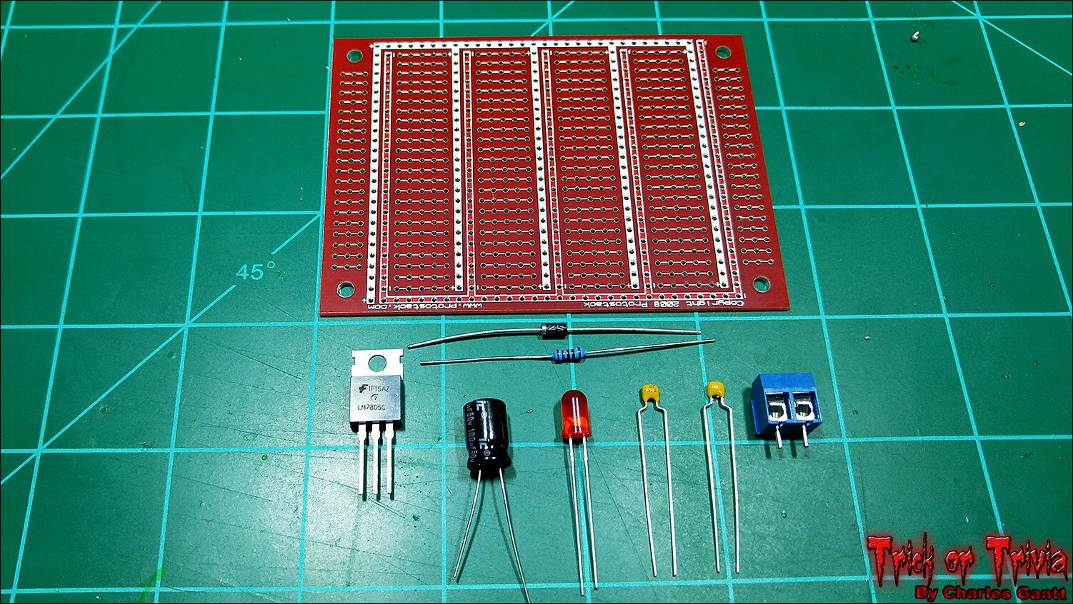
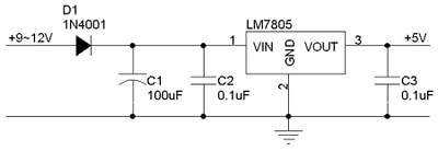
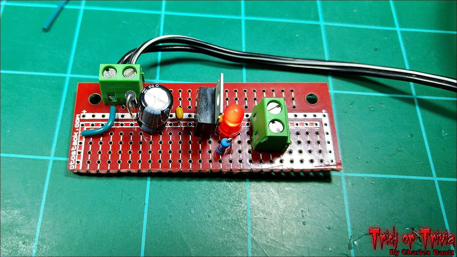
A 5V regulated power supply circuit is quite simple to build thanks to the fairly common LM7805 voltage regulator, and requires just five components to get up and running. A 100uF capacitor, two 0.1pF ceramic capacitors, a 1N004 diode, and the LM7805 regulator. I am adding two screw terminals, and an indicator LED to the mix. I want to design a pcb for this, but for now a piece of protoboard will work just fine.
Following the schematic above, build the power supply and solder in each component. The protoboard I am using is different from the one listed above as I have a big supply of these from Protostack.com, so I just used one of mine.
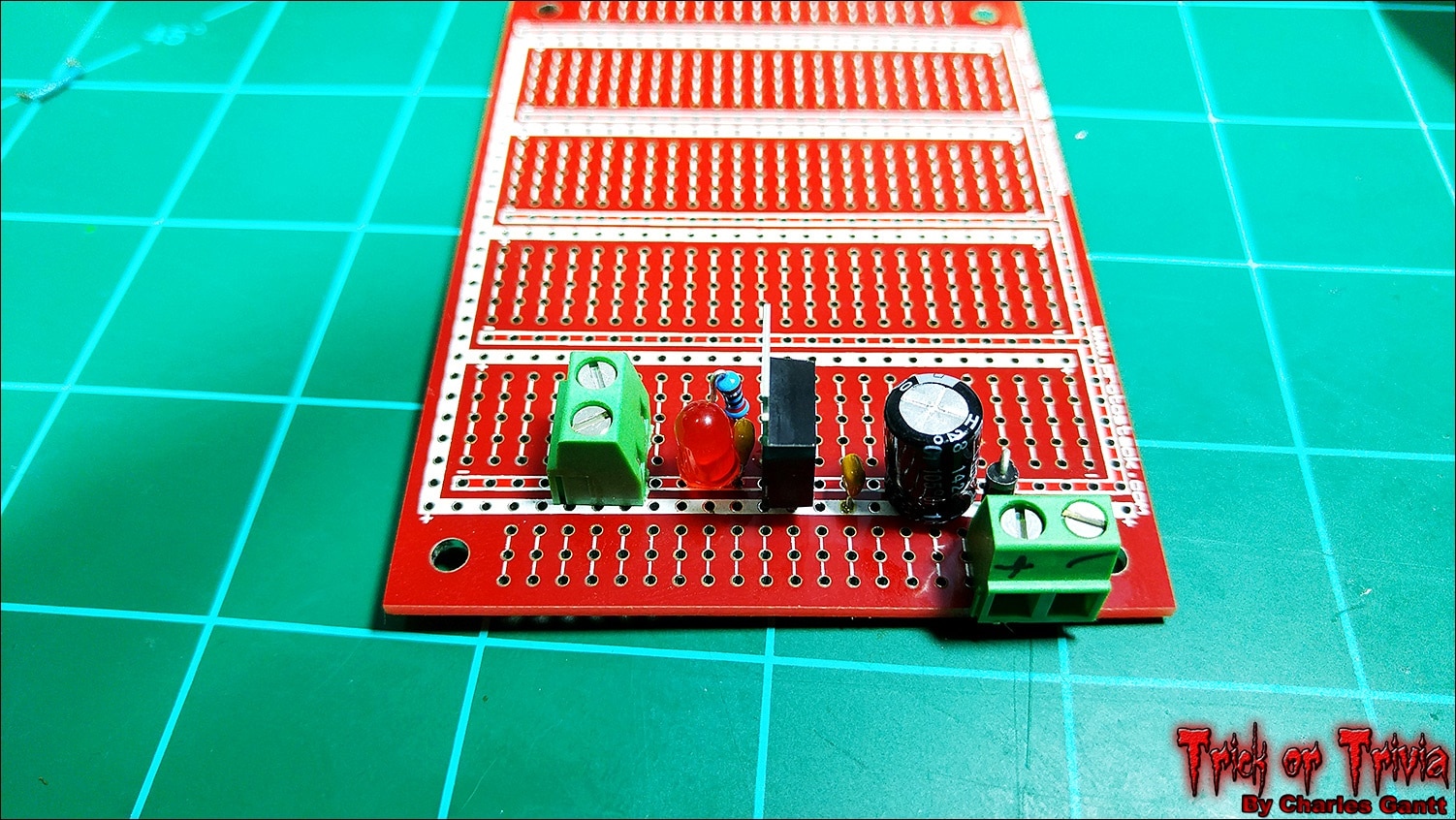
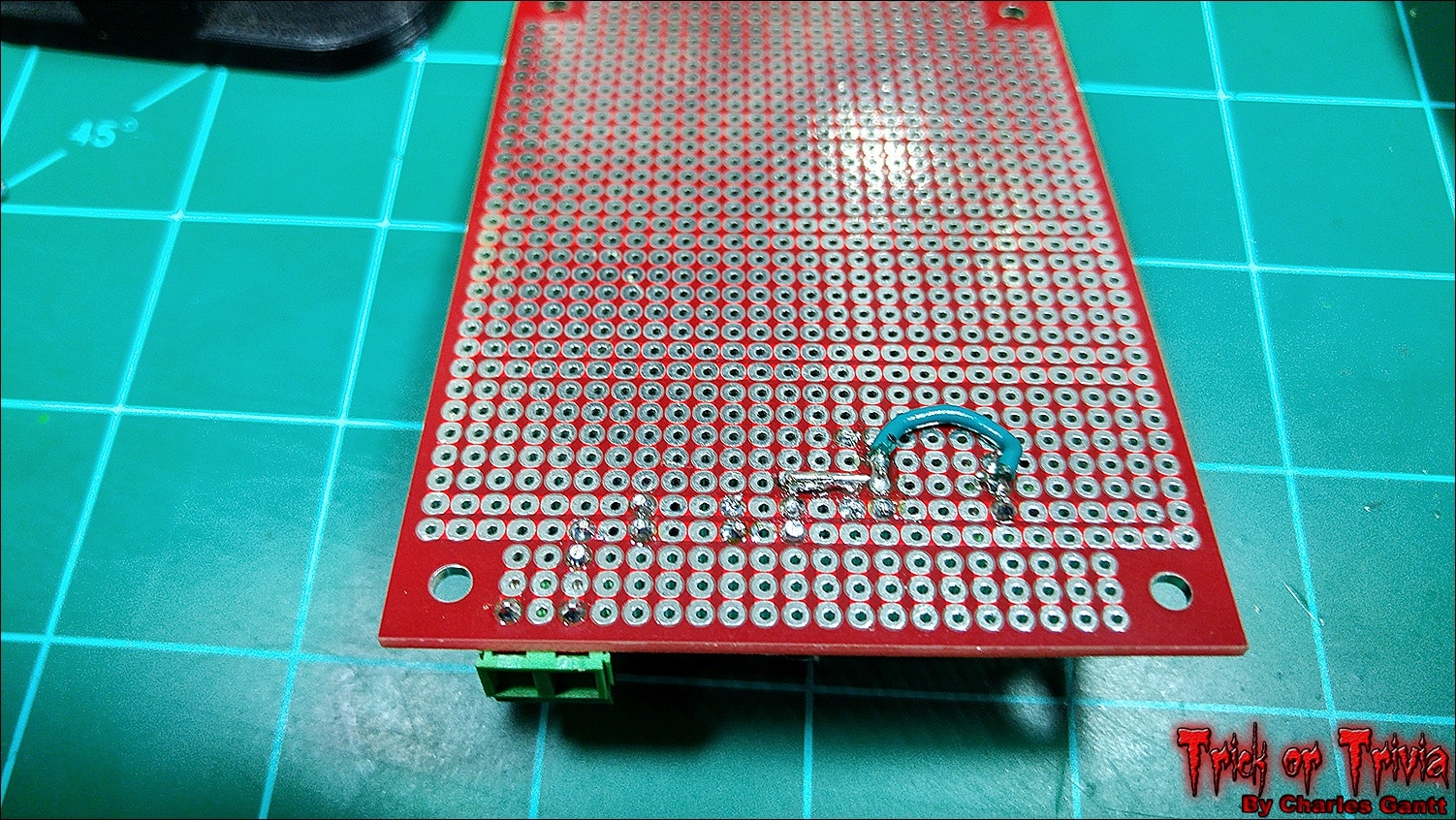
With all of the components soldered together, I made the necessary jumps from each component to the next. I lucked out with the Protostack board as it has integrated power and ground rails. This cut down on the number of jumps I needed to make.
With everything soldered up, I trimmed the board down to reduce its size, and connected a 12v 1amp power source. The red LED lit up and I confirmed 5V out with a multimeter.
With the power supply built and working, we can move on to testing our servo!
Testing the Servo
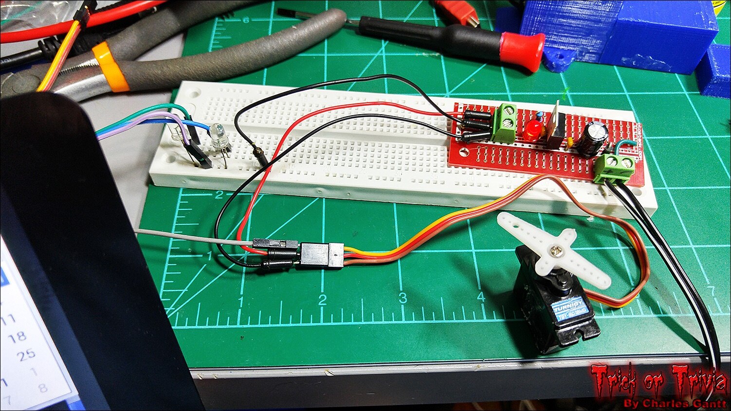
Connect the servo to the power supply as shown. Then connect the servos signal wire to the Raspberry Pi’s GPIO Pin 4 using the BCM schema. You also need to connect the power supply’s ground to the Raspberry Pi’s ground. You can see that I have done that here with the GND rail on a breadboard I am using to power the mock-up’s LEDs.
To test the servo, let’s create a new test script with Python. Using the Nano text editor create a new file within the Trivia Scripts directory using the following commands.
cd /home/pi/Desktop/TriviaScrips
nano servo_test.py
Now paste the following code into the file you just created. Then exit out of the file, saving the changes.
import time
import pigpio
import sys

servos = 4 #GPIO number

pi = pigpio.pi()
#pulsewidth can only set between 500-2500

def correct_servo ():
        while True:
            pi.set_servo_pulsewidth(servos, 2500)
            time.sleep(.5)
            pi.set_servo_pulsewidth(servos, 1300)
            time.sleep(.5)
            pi.set_servo_pulsewidth(servos, 2500)
            time.sleep(.5)
            pi.set_servo_pulsewidth(servos, 1300)
            time.sleep(.5)
            pi.set_servo_pulsewidth(servos, 2500)
            time.sleep(.5)
            pi.set_servo_pulsewidth(servos, 1300)
            time.sleep(.5)
            pi.set_servo_pulsewidth(servos, 0);
            pi.stop()
            break


def incorrect_servo ():
    while True:
        pi.set_servo_pulsewidth(servos, 2500)
        time.sleep(.5)
        pi.set_servo_pulsewidth(servos, 1300)
        time.sleep(.5)
        pi.set_servo_pulsewidth(servos, 0);
        pi.stop()
        break

correct_servo()
incorrect_servo()
sys.exit
To run the script, use the following command.
sudo python servo_test.py
The servo should move back and forth a few times before finishing up, and the script terminating. If it worked, copy the full foginator code that I posted earlier in this post, and edit the foginator2000.py script. Delete the existing code and paste the new code into it. Save and exit. Now you should be able to run the Foginator2000.py script and when you select the correct answer, three pieces of candy will be ejected from the magazine like in the video below.
I apologize for this post being so late, but as you might know, South Carolina got hit by a pretty massive rainstorm over the last few days. That has seriously hindered my ability to work on anything, but we are back to blue skies now. I hope you enjoyed this installment of my Trick or Trivia project, and I hope that you learned a thing or two about the Raspberry Pi and servos. That is going to wrap this installment of Project: Trick or Trivia. Check back in a few days for the next installment. Until then, remember to Hack The World, and Make Awesome!
Project Introduction
Building The Trivia Interface
- Interfacing Ambient and Triggered Audio Events
- Building The Candy Dispenser & Servo Coding
- Carve Foam Tombstone
- October 24th - Assembly and Testing
- October 28th - Project Wrap-up
Top Comments