


Table of Contents
Introduction
This blog post discusses a Pi Pico-based ultra-low-cost robotics card, intended for controlling electromechanical components (mainly motors, but in theory, other things could be controlled too). The board could be used to build robots of a size with a footprint of, say, a paperback book.
There is a 6-minute video (direct link here) that explains it:
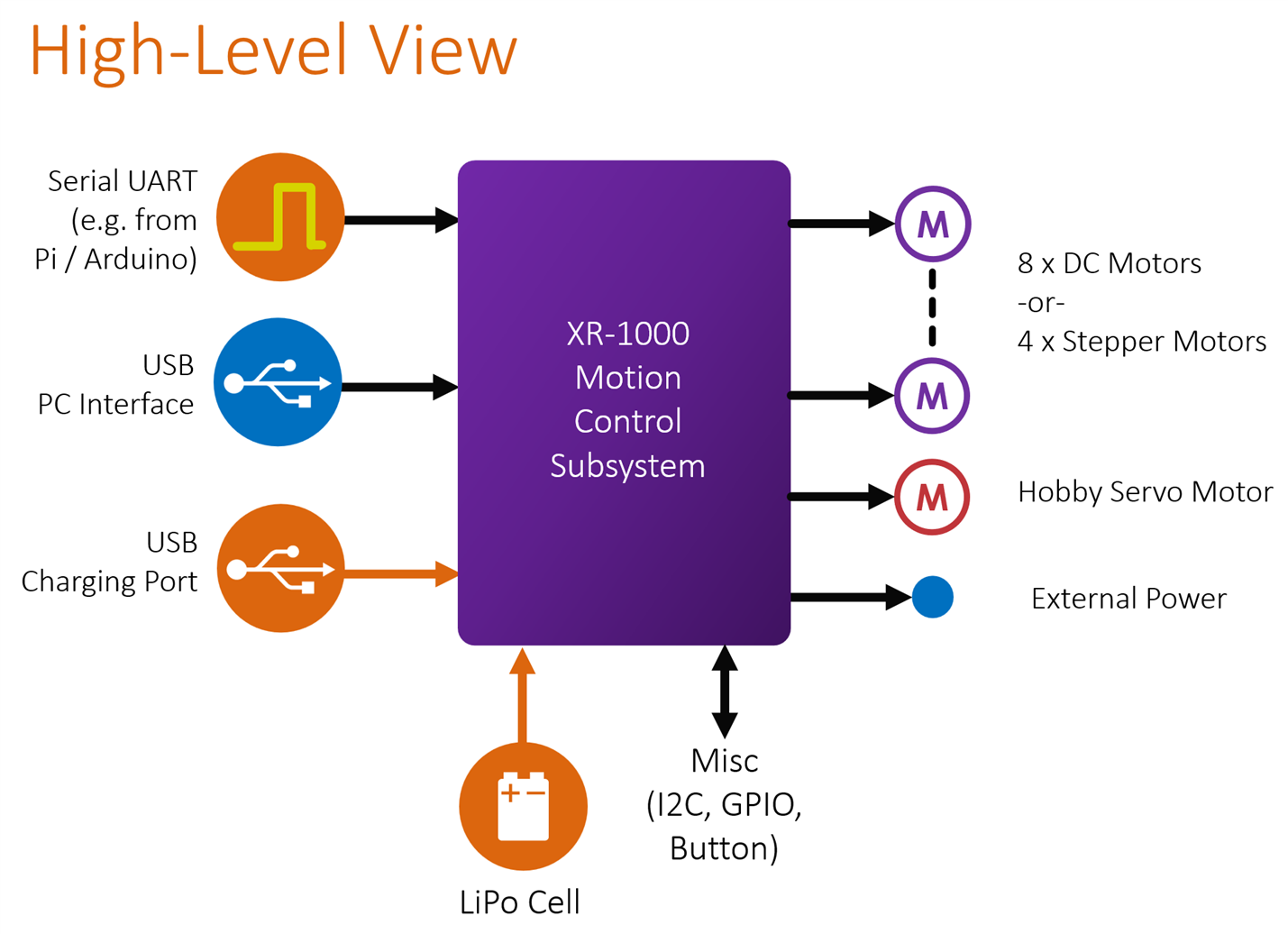
The concept is simple to see in the diagram below – on the left side are various interfaces for controlling things, and on the right side are the connections to motors.
The left side desired interface is selectable. The board can be used in a standalone mode, or, it could be attached via a serial connection to any other board, or it could be attached via USB to a PC.
The board mainly uses off-the-shelf motor driver modules, LiPo charger, and DC-DC converter modules, all available from Aliexpress. The semiconductor shortage doesn't seem to have impacted the supplies of such modules, which helps. The few surface-mount components on the board are large (about the size 1/8W wire-ended resistors, just without the wire ends) and that makes it hand-solderable with no special tools.
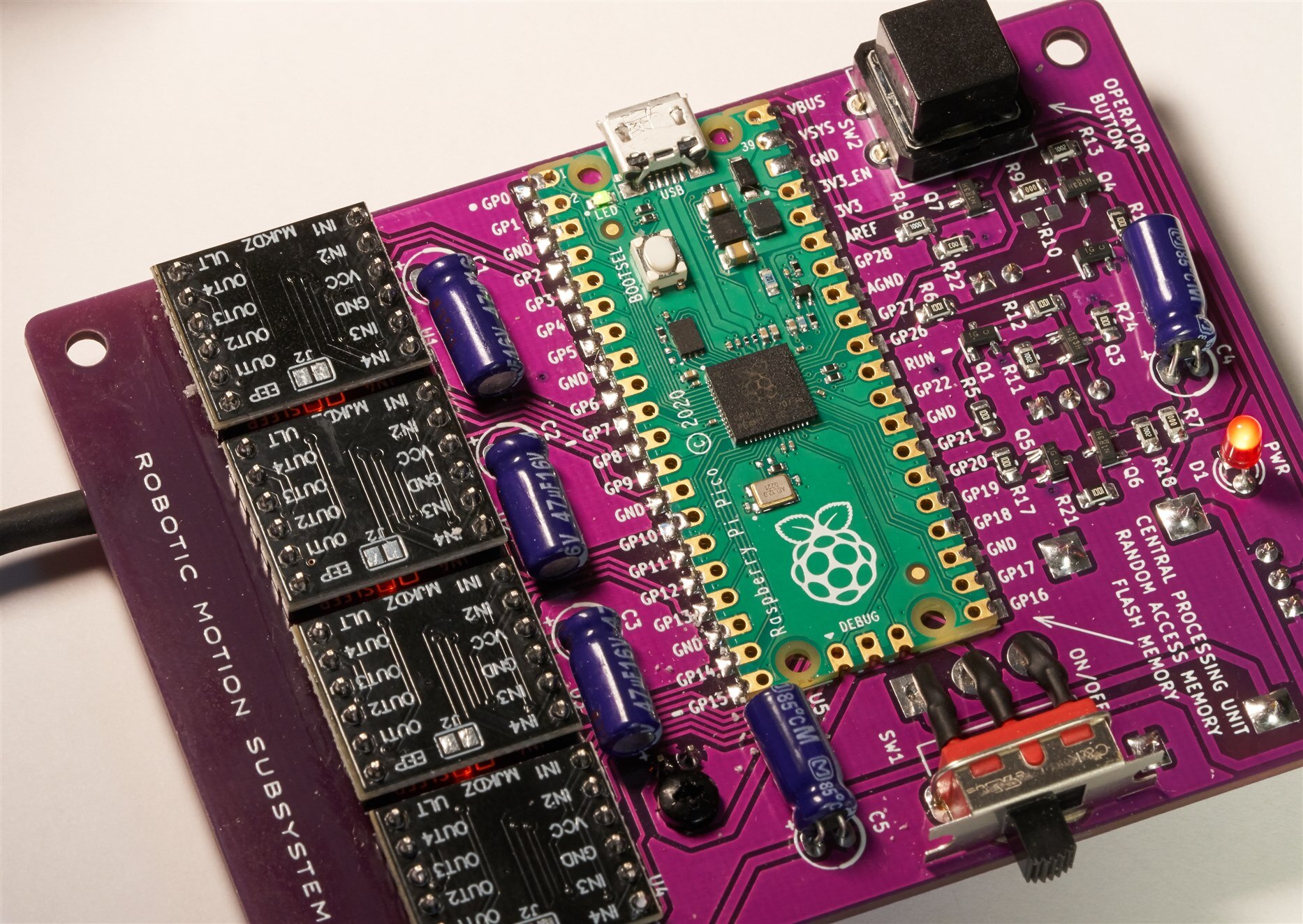
This project is called the XR-1000 eXperimental Robotics Motion Subsystem board.
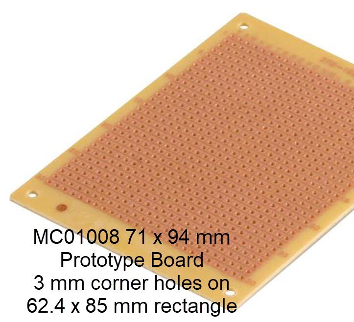
If desired, the board can be stacked and screwed together with compatible-sized perfboard (Multicomp MC01008 or Radio Shack # 276-158 or #276-158B), or any custom board with the same dimensions if desired.
Operating the Board
The simplest method is to plug in some motors and a battery, press the on-board Operator button, and the board will begin moving the motors in a pre-set pattern (It will cause the robot to move forward, turn 120 degrees, move a similar distance forward again, and repeat, i.e. the robot will move in a triangular path).
Here are some other ways to control the board:
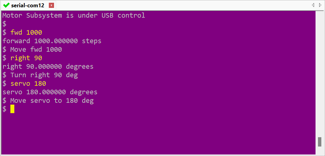
Method 1: PC command-line interface via USB
If you hold down the Operator button on the board while plugging in the USB connection and powering it up, you have several seconds to hit Enter on your console software (such as PuTTY) on your PC, and a command-line interface appears. You can then type a few LOGO-like commands such as fwd 1000, an example is shown here:
Method 2: Serial (UART) connection
There is a connector to attach to boards such as Arduino or Raspberry Pi. The UART connection automatically becomes the default operation mode if no other mode is chosen. The remote board (Arduino, Raspberry Pi, etc) can communicate in a M2M (machine-to-machine) style. The commands look similar, but the responses are tailored for a machine to understand them easier, rather than the more verbose output from the command line version. Here is an example:
fwd 1000
PR
OK
In the example above, the remote board sends an instruction to move the motors forward by 1000 steps, and the XR-1000 motion board responds immediately with PR which means PRocessing, and then after the motors have completed the entire motion, the motion board responds with OK that indicates it is ready for a new command.
If an undecipherable command is sent from the remote board, then the motion board will respond with BR which means Bad Request.
Incidentally, the USB mode can also be used in an M2M manner too; it isn't necessary to use the serial UART for M2M. To use the USB mode for M2M, the command m2m needs to be typed, and then the USB mode will switch to the M2M style of responses, until exit is typed by the user.
Ordering the Parts
Some parts were ordered from Farnell/Newark, however, orders were also needed to be placed with AliExpress for various specific items, since the board relies on so many ready-built modules. You could install fewer modules if you don't need to drive many motors, but the modules are inexpensive. See the motion control board bill of materials, which contains the AliExpress search terms to locate items.
The circuit board can be ordered from any PCB manufacturer – I used JLC PCB, but others like Elecrow and iTead will do just fine too. The board PCB files are on GitHub.
Building It
There is not much to go wrong. The four important things are:
(a) There are a few large surface-mount parts, they can be hand-soldered like any through-hole component, but a good pair of tweezers helps to hold them in position
(b) Solder all resistors first, then solder the semiconductors. The MOSFETs could get damaged otherwise. It is suggested that components are soldered in the order they are listed in the Bill of Materials (BoM).
(c) The LiPo charger module needs a plastic (e.g. nylon) nut and bolt to secure it. The nut or bolt should definitely not be metal.
(d) Make sure the battery polarity is correct! Some LiPo batteries come with the connector wiring reversed. There is printed information on the PCB near the battery connector, to act as a reminder of where the red and black wires must go. For this project, it is better to use a battery with a connector, rather than a battery with a separate battery holder.
Motors
The motors connect using 4-pin Molex PicoBlade connectors; up to two DC motors, or a single 4-wire stepper motor can be wired to each connector. The motors should be intended for 5V or 6V operation, with ideally at least 20 ohm DC resistance. The photo below shows some of the motors that I tried which worked, and the AliExpress search terms are in the bill of materials. The video shows two motors rotating with a 50:1 gearbox ratio, which could be suitable for attaching to wheels although I have not tried to do that yet. You might want to try a couple of different ratios and then select the best one.
The board supports one hobby servo motor, the one in the photo is called SG90 Micro Servo 9g.

If the motor doesn't come with a Molex PicoBlade connector, there's no need to try to crimp such tiny connectors, because both Farnell and AliExpress sell ready-made, pre-crimped cables that could be attached to the motor. I had to do that for motor 4 in the photo above; you can see the heat-shrunk insulation where I made the join.
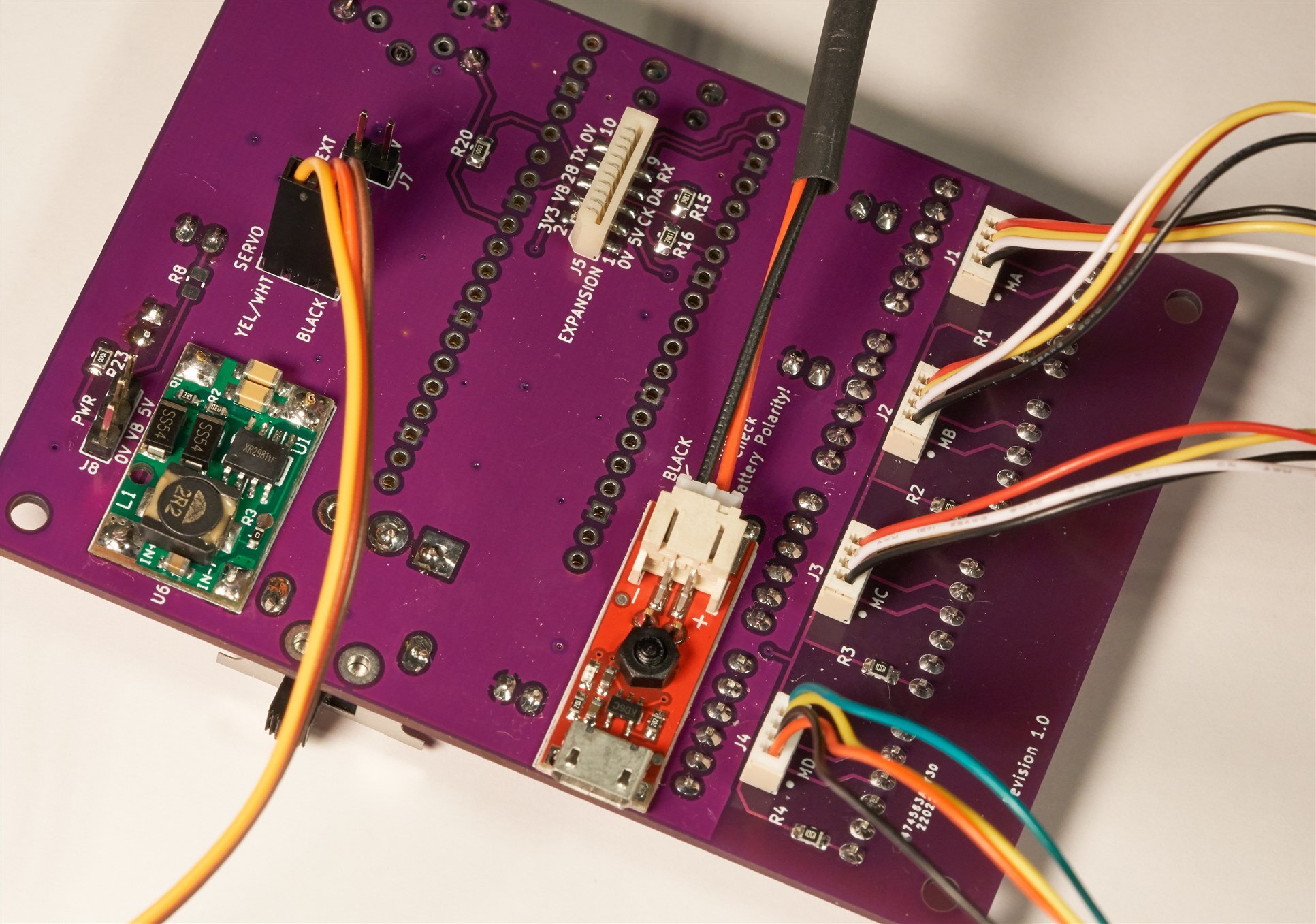
The photo below shows how all the motors plug onto the board and the battery connection in the center of the photo. The expansion connector at the top of the photo provides access to the serial (UART) interface, along with I2C and general-purpose input/output (GPIO), and power for add-ons. On the left side, there in another connector for powering additional boards, plus there is a connector marked EXT, which provides switchable 5V DC power (i.e. under programmable control from the Pico). If no servo is required, then the servo connector provides two more switchable power outputs.
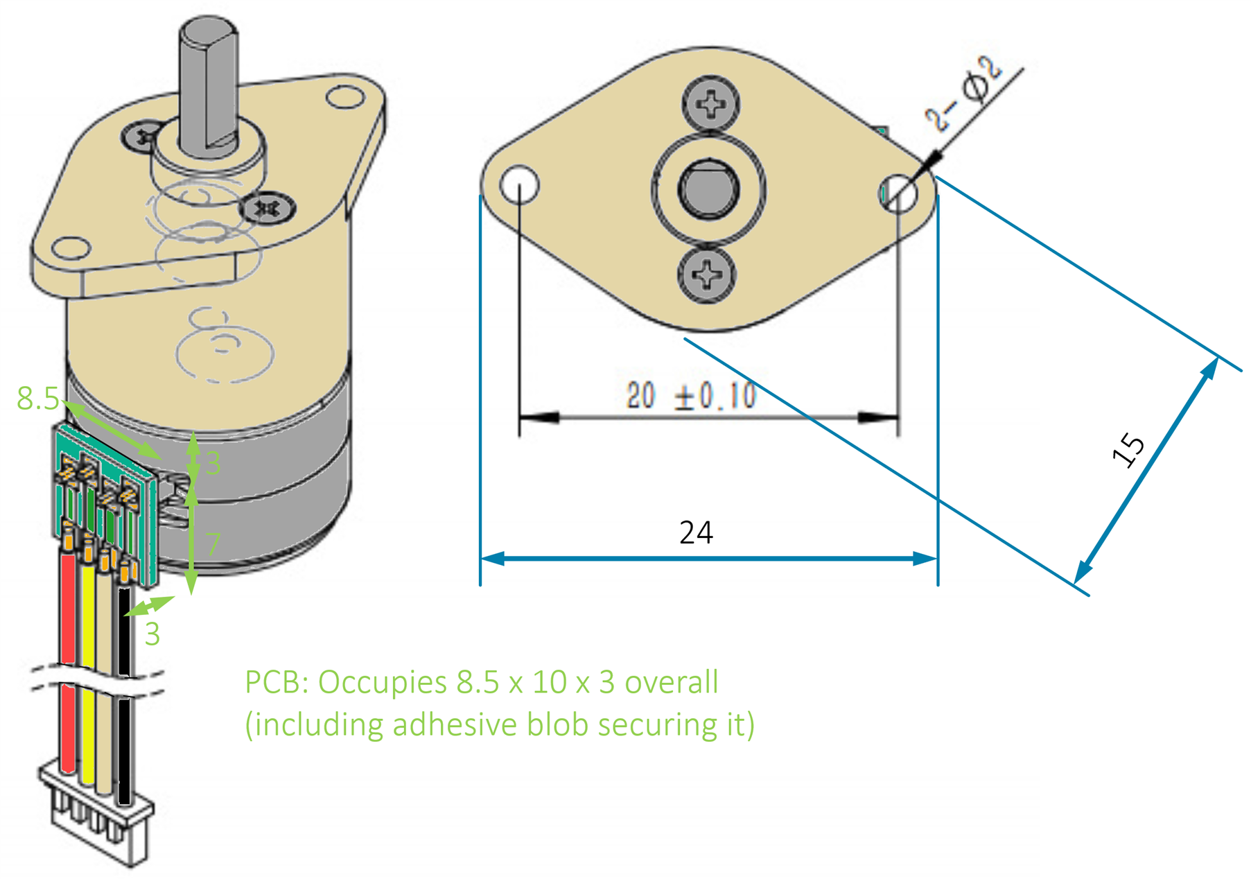
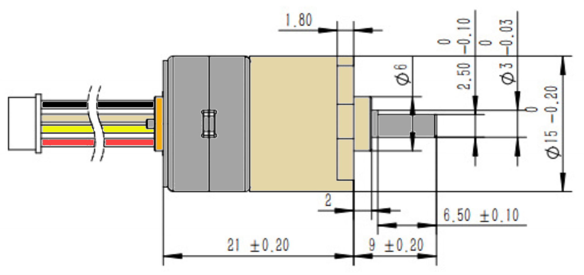
The white-colored plastic motors in the photographs above are available as mentioned from AliExpress, using the search term that is in the bill of materials. The dimensions are shown in the drawings below (taken from the AliExpress page and colored to make it a bit easier to follow) in case a bracket needs to be 3D-printed for (say) connecting to Lego or Fischertechnik parts. I have checked with calipers and the measurements are accurate. The cable is approximately 115 mm long.
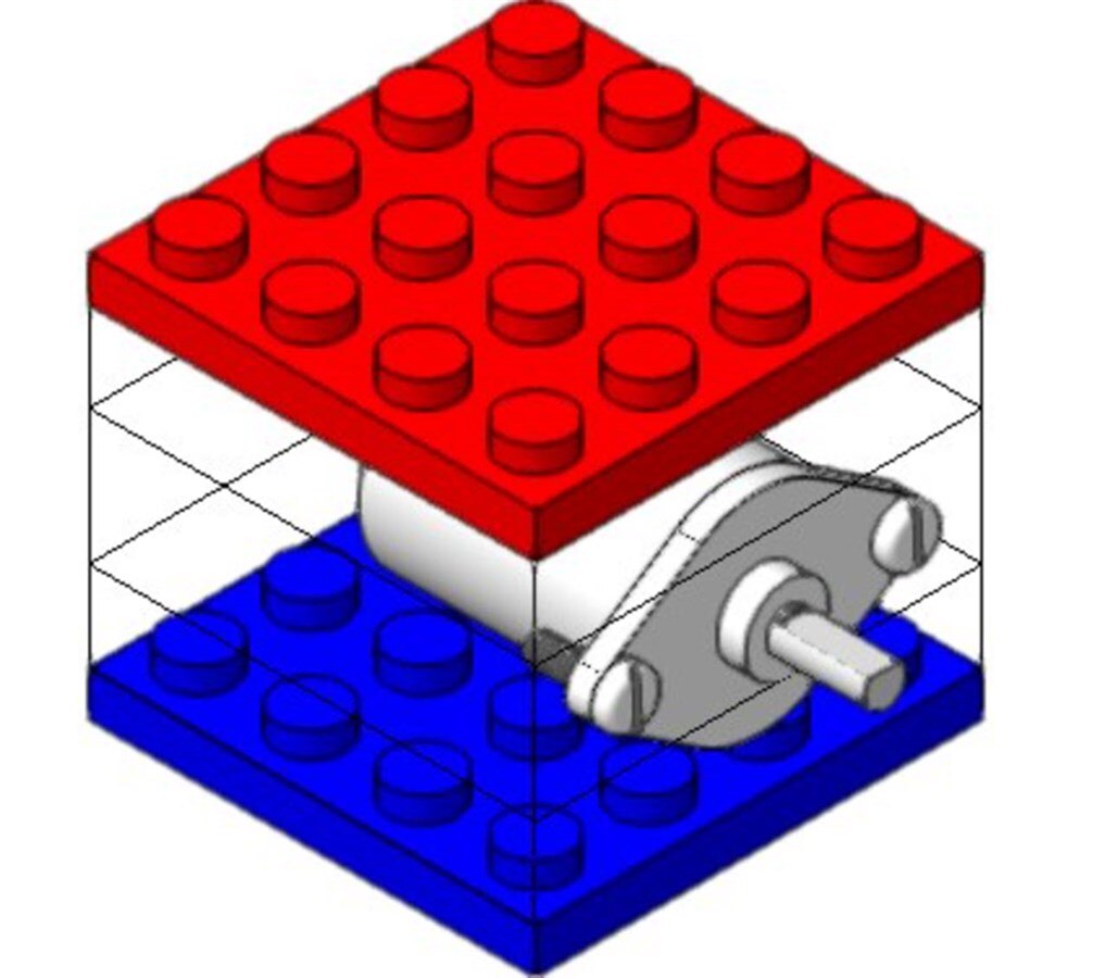
beacon_dave has done some Lego compatibility investigating (see the comments here), and it turns out that the motors could potentially be adapted with a 3D printed portion surrounded top and bottom with Lego plates, as shown here (the green portion would be 3D printed):
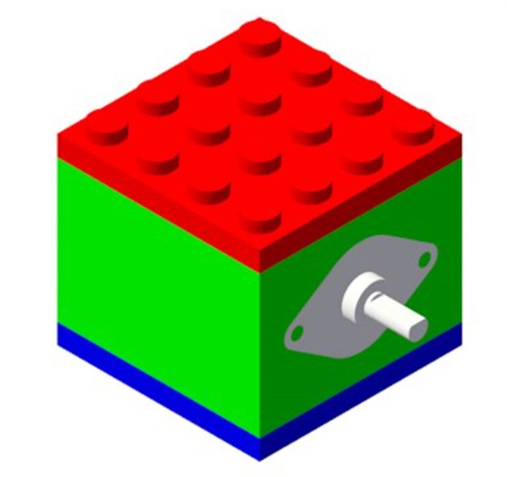
The overall design including the top and bottom plate is exactly three normal bricks high (or 9 plates high):
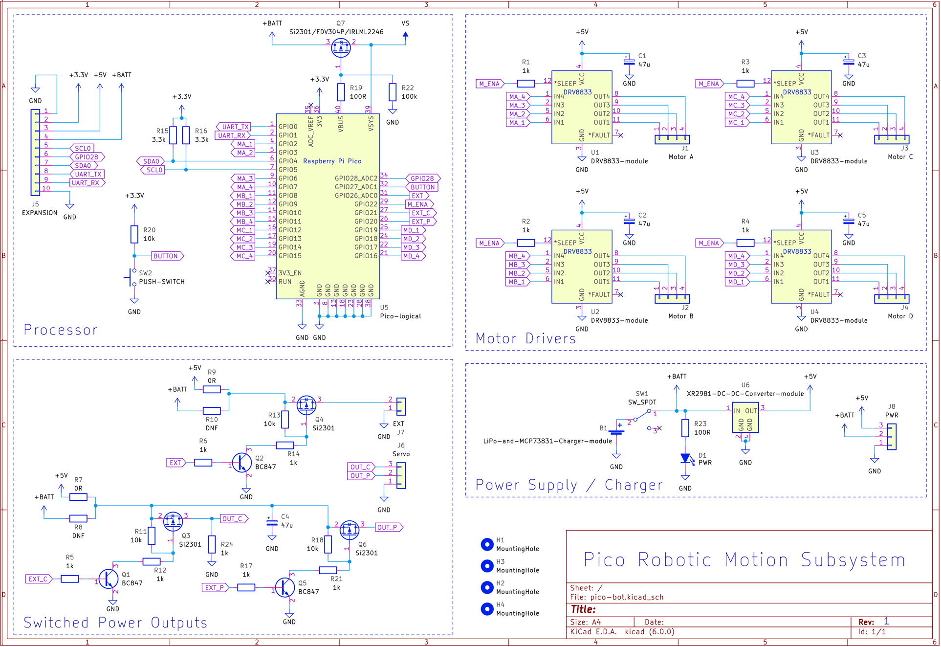
Circuit Diagram
The entire circuit is shown below (there is a PDF copy of the schematic in GitHub). One minor point is that to conserve power, the four DRV8833 motor driver modules might each require a resistor to be de-soldered, which is described further below. The ones that came from AliExpress were already missing the resistor, so that was good. With the resistor removed, the Pi Pico can shut down the motor drivers, which is handy for the times that the robot is physically idle and "thinking", or while the user is typing commands : ) In a similar vein, the hobby servo motor driver is slightly unusual in that it can shut itself down, which can save a lot of battery power for scenarios where a light load can be held in position by the unpowered motor and gearing inside the hobby servo.
Printed Circuit Board
The circuit board layout is shown below. An important thing is to check the battery polarity against the marking on the circuit board because some LiPo cells or cables come with swapped-around wiring. If the polarity is wrong, then the battery should be replaced with a different one, unless you can safely remove the terminals from the socket (without shorting the battery!) and swap them around.
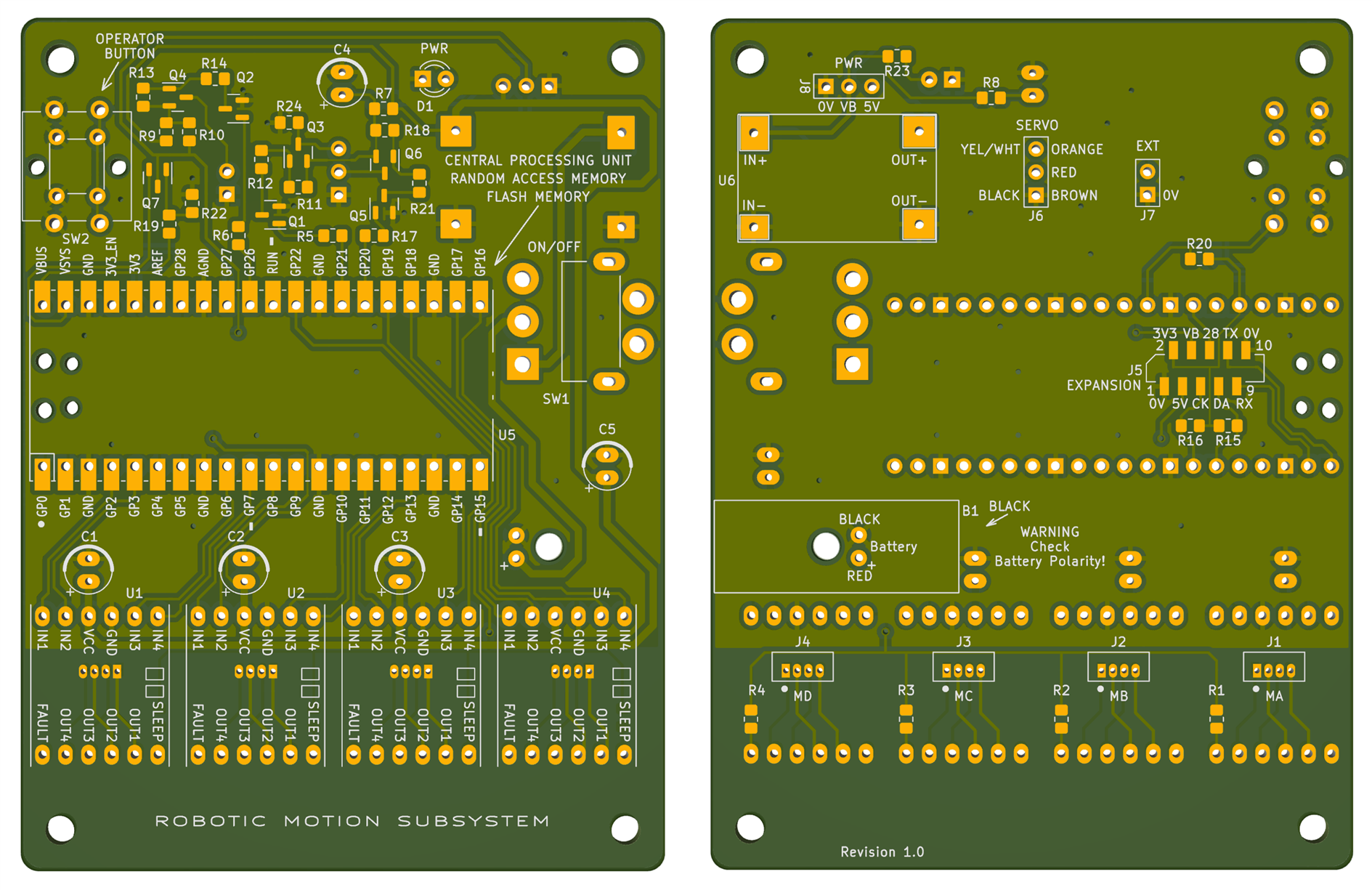
The expansion connector J5 uses a flat flex cable (FFC) with wide spacing (1mm) to make it easy to work with. I figured it would give a neater result than running many jumper wires.
If you need to use jumper wires, then although you could solder wires directly to the pads, an alternative option is to make an adapter cable by soldering wires to another flat flex connector, and then use PolyDoh pellets to make a connector shell : ) I used PolyDoh in the photo below. This adapter cable exposes the serial UART pins RXD and TXD, and GND.
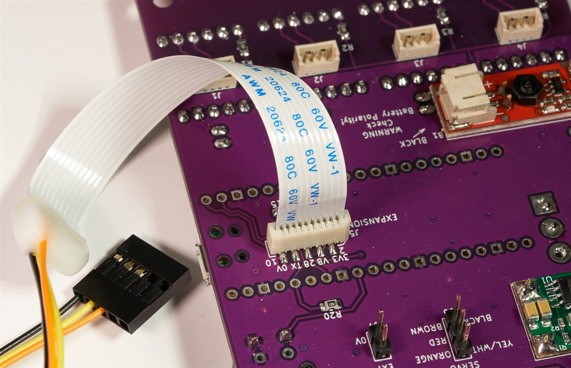
To make the connector shell, I heated a dozen of the small pellets of Polydoh using a hot air tool (set to low airspeed to prevent the pellets from blowing away) and then just pressed it by hand onto the back of the connector (it is hot but doesn't have enough heat to burn). When it cools it becomes rock-hard.
Uploading Firmware to the Board
The source code is on github, but there is also a ready-built firmware image there called motion_controller_prebuilt_firmware.uf2 which can be used. To use the ready-built image, take the unpowered board, hold down the white button on the Pico module, and plug the USB connection into your PC. After a second, release the white button. You'll see a drive letter appear on the PC (the board looks like USB storage). Drag the ready-built firmware image onto the drive letter, and the board will program itself within a few seconds. Now the board is ready to run, and motors and the battery can be connected. A quick test will be to press the Operator button when the board is powered up, and the motors attached to connectors J1 and J2 will rotate (they will spin in order to travel in a triangular pattern; this is the pre-set pattern inside the firmware).
Code Description
The main.cpp file contains a while loop that forever waits for, and handles requests. The same file contains functions called rotate_wheels, move_servo, rotate_motor and ext_pwr, and they are all fairly self-explanatory (ext_pwr switches on/off the power to external devices connected to the header pins labelled EXT).
Motors can be configured to act individually, or in pairs for wheels. Making a single motor rotate is done using the SMotor::step(n, dir) function which steps the coils n times in the chosen direction. Pairs of motors use the SMotPair::step(n, dir) function, where the direction can be a value 0-3, for motion backwards, forwards or left or right turns respectively. It is assumed that motors need to turn in opposite directions to move the robot in a straight line, and in the same direction to cause a rotation left/right.
The current code assigns a pair of motors to J1 and J2 connectors, and separate motors to J3 and J4 connectors, but it is possible to edit the code of course.
The command line code is in femtocli.cpp, and it implements a lightweight menu system, with some basic sanity-checking (not a lot). The current implementation only accepts the syntax:
command [param1] … [paramN]
where param1..n are optional or mandatory depending on the command. It accepts numerical input for parameters with multipliers like k for 1000, e.g.
fwd 1k
is the same as:
fwd 1000
A timer interrupt is used to execute a callback in the file repeatedly. Once that executes, USB and UART input buffers are checked and command lines are parsed whenever the user presses Enter. There are some shortcuts, for instance hitting the exclamation-mark key twice, i.e. !! will execute the last entered command again.
There is an admin menu which will be used to store robot configurations/sequences, but there are only placeholder commands there for now.
Building the Code
If you want to make changes to the firmware, you'll need to re-build the code. To do this, on a Linux machine (e.g. a Raspberry Pi, or any Linux box), first create a development folder off your home directory, called (say) development, and then go into that folder, and follow the steps in the Pico Getting Started PDF document to install the Pico Software Development Kit (SDK).
In my case, the SDK path was ~/development/pico/pico-sdk
Next, edit the .bashrc file in your home folder with the following lines at the end (modify these lines to suit your precise home folder pathname):
# PICO SDK
PICO_SDK_PATH=/home/your_username_here/development/pico/pico-sdk
export PICO_SDK_PATH
After that, close and open the shell, so that the .bashrc file can be re-read by the shell.
Next, from the development folder, type:
git clone https://github.com/shabaz123/xr-1000-robotic-motion-subsystem.git
To build the code, type:
cd xr-1000-robotic-motion-subsystemmkdir buildcd buildcmake ..make
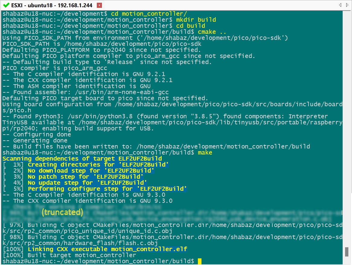
After a few minutes, you should see a file called motion_controller.uf2 in the build folder. That's the firmware file that can be uploaded to the board using the method described earlier.
Next Steps
The next step is to use the project! : ) It would also be good to extend the software. For instance, it could be good to implement acceleration/deceleration in the code.
The preset program function could be greatly extended. It should ideally be feasible for the user to be able to test out motion commands using the command line and commit them to Flash memory so that they can be replayed later.
There are bound to be bugs in the code, although the major functions seem to work fine. One annoying bug which I'd like to fix, but I didn't get very far with, is that there seems to be a limit (I believe it is 256 bytes) when sending text responses over the USB interface. The limit is annoying because when the user types help, the code tries to send more than 256 bytes, but only the first 256 are printed. As a result, the help feature is useless until the bug is fixed or a workaround can be found. I can't issue a sleep instruction, because that seems to cause the Pico to hang (that portion of code executes in a timer callback, and I didn't want to redesign that part of the code structure, because otherwise, it works well).
Thanks for reading!
Disclaimer
Note: Although toy robots may be desirable for kids, this is an engineering blog post, written for engineers. The battery should be disconnected after use, and not left unsupervised while charging. There's no product guarantee with charging modules, DC-DC converters, and other parts from AliExpress, they could be built anywhere with varying quality. The project described here has not been tested or certified in a lab, it may have faults. When building robots, don't use flammable parts, and ensure that wire insulation and the battery are protected from sharp metal objects such as a chassis. Ensure the battery has built-in protection circuitry, and also consider soldering in a fuse once you've determined the current consumption of your project with the motors you're using.
Top Comments