

Gaming is the perfect way to help newcomers to the Raspberry Pi to connect it with a recognisable lifestyle technology. It's the perfect stepping stone to bring people eye-to-eye with the Raspberry Pi; if it can play all those awesome, classic arcade games, it can also do so much more!
And that's why gaming is often our go-to project when it's time to show people what the Pi is all about. But this time around, with the Raspberry Pi 3 now in the wild, we wanted to do something a little bit different, too. So here's how to make your own minimalist, contemporary interpretation of the classic coin-op cocktail cabinet that uses an IKEA coffee table and a Raspberry Pi 3.
Meet the PIK3A Gaming Table!
Parts, Bits and Pieces
So here's the gist of this simple, but super-stylish project.
It's an IKEA Lack coffee table with an LCD monitor cut into the top, arcade controls next to the monitor, and a Raspberry Pi 3 and accessories buried inside the table.
Let's begin with an overview of the parts you'll need:
- The Cabinet: IKEA Lack coffee table.
- The Brains: Raspberry Pi
- The Controls: Arduino Leonardo
- The Joystick: A classic, four-way ball-top joystick.
- The Buttons: From CPC - From MCM
- The Display: An old 17" LCD monitor (4:3 ratio is better given the square shape of the table).
- The Sound: This pair of USB-powered computer speakers.
- The Power: A Raspberry Pi 2.5A USB power supply, and a mains extension.
- The Stuff: Cables, connectors, screws.
Table Top Gaming
This isn't really intended as a woodworking project, but we trashed at least one table when prototyping this so maybe we can help you to make only the holes the table needs. So, let's begin with the hacking and sawing, and then we'll look at the innards.
Dismantle Your Monitor
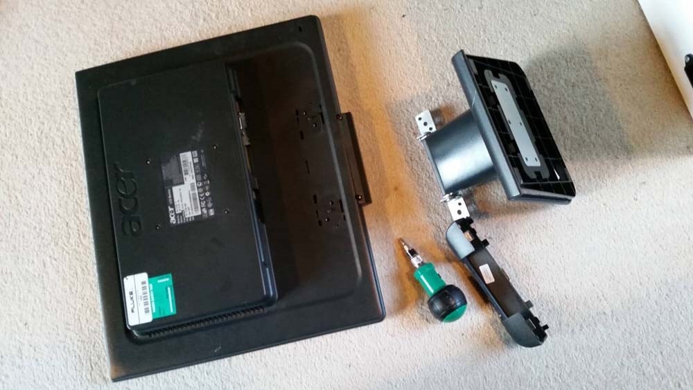
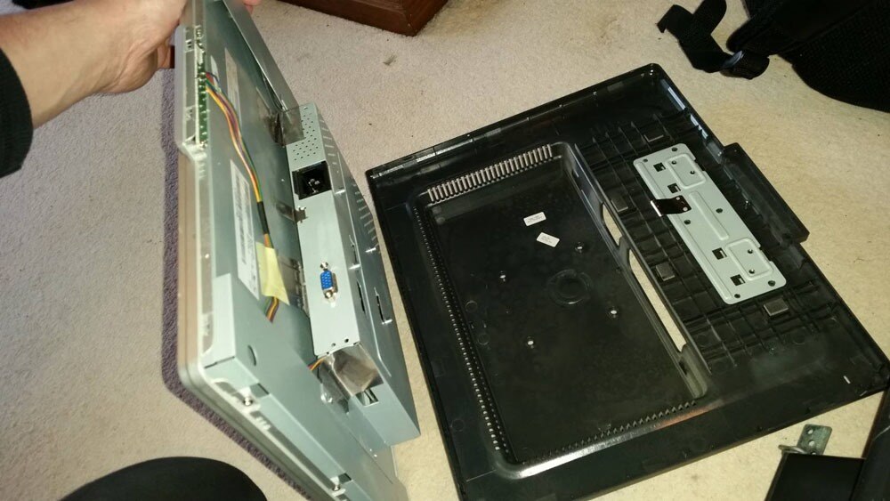
The old Acer AL1716 monitors we used seem fairly generic, in terms of 17" LCD screens, so hopefully yours will pan out the same. By taking the screen chassis out of the plastic casing (nothing complicated there -- take out the screws and prize the two halves apart) you should be left with the screen inside the shielding housing that's almost exactly the same depth as a LACK coffee table. This means that once you've got the screen, all you need to do is drop it into the hole we're about to cut into the PIK3A table top.
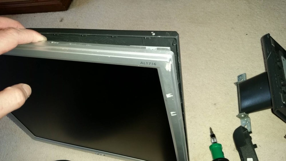
And by removing the bezel around the LCD, the screen will sit flush with the top of the table, and give you that essential minimalist finish.
| {gallery:autoplay=false} Removing the LCD from the Monitor Housing |
|---|
|
Remove the stand, and any screws in the back of the monitor's housing.
|
|
It's probably all clipped together, so carefully pry the back of the housing away from the silver bezel around the screen.
|
|
You don't need to remove any of the shielding inside once the housing is apart. This is better left in place, to protect the back of the LCD. Note that you might need to relocate (and protect/insulate) the small PCB with the monitor's buttons on.
|
|
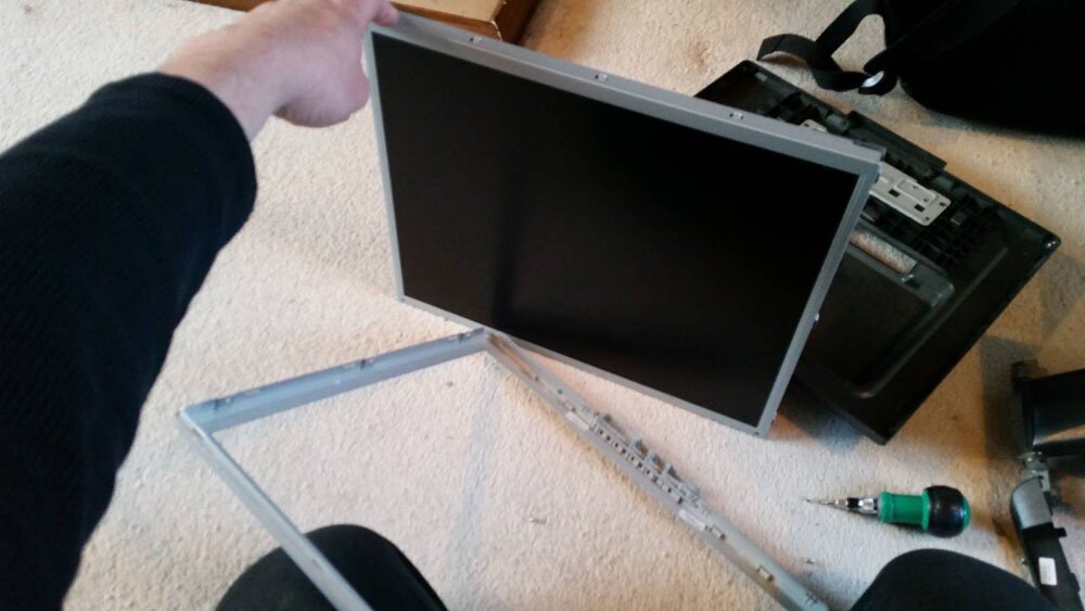
Remove any small screws that fix the bezel to the LCD's shielding.
|
|
Leaving you with an LCD panel that'll sit nice and flush to the table top.
|

Screen Mounting
The first time out we used a Dremel with a router attachment to cut the hole in the table top for the monitor, which actually worked very nicely. However, these ultra-cheap tables really don't warrant that much power tool action, when a Stanley knife does the job just as easily and with a lot less mess. The choice is yours, of course.
Below you can see how we drew around the screen to get the sizing for the hole, and then drilled 13mm holes in each corner to give the cut-out some nice, radius corners.
Clamp a straight edge along the outside of the line you want to cut, and repeatedly run the knife along it. Remember not to cut all the way into the hole on the opposite side from where you started. Chances are the knife will continue and make a mess of the nice radius you put in there. Instead, stop 10cm short and cut again from the other end.
Go around all four sides (it won't take a lot of effort) and prize out the cut-out piece. It won't just come free, as it's glued to the structural filling inside the table, so take care when prizing it up so as not to damage the surface of the table. Run a knife around the honeycomb paper filling, and pull it out. You now have a hole to drop the monitor in.
| {gallery:autoplay=false} Mounting the Screen in the Table |
|---|
|
Lay the dismantled monitor on the table and draw around it. I also put the joystick and buttons roughly in place, to help locate the monitor in its ideal position.
|
|
Use the drill bit for the corners to mark where to drill. This'll give you nice, rounded corners on the cut out.
|
|
Drill the four corner holes for the cut out.
|
|
Mask off the area around the hold, to protect the surface of the table when you clamp a straight edge to it.
|
|
Clamp a straight edge to the outside of the cut out (so if you slip, the damage will be on the piece you're removing), and make lots of gentler cuts from one hole along the straight edge, stopping short of the second hole. Cut from the second hole, back along the same line to prevent the knife from slipping and damaging the radius of the second hole.
|
|
When you've cut right through the table top on all four sides, carefully pry the cut out up. It'll be stuck to the innards of the table, but will come free with a little effort. Save the cut out for later on.
|
|
Run a knife around the honeycomb and rip it out.
|
|
You've a nice, neat, monitor-shaped hole in the table!
|
|
If it's all gone well, take a moment to feel a little smug about yourself.
|


Control Mounting
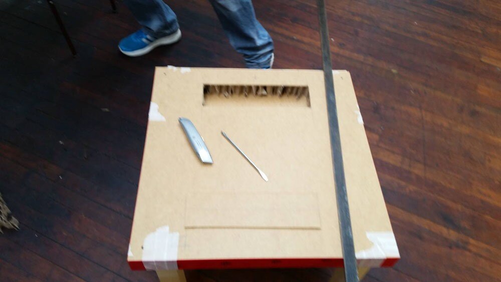
Flip the table top over and cut a letter box into the back. This gives you access to the inside-back of the table top so you can mount the joystick and buttons. Cut it out the same way as before and remove the honeycomb.
Mark where you want to mount your joystick and buttons -- we went with four buttons -- and drill 28mm holes for each one. This is the standard size for arcade buttons, and also gives the joystick plenty of room to move without the hole being visible around the round, flat cover that comes with the joystick.
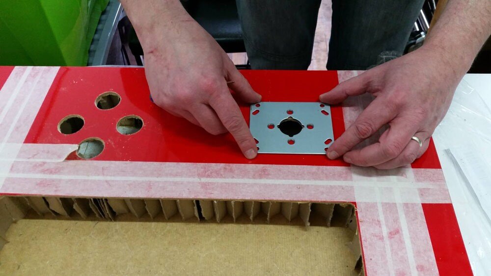
But we didn't want any fixings visible on the PIK3A table top, which meant we couldn't use the mounting holes in the joystick's plate. Instead, we removed the mounting plate and used the screws that attach it to the body of the joystick (where the microswitches are) to fix the joystick in place. They're a little bit short, but when you countersink the holes in the table top, they'll still reach and grab hold of the thread solidly.
You'll need to remove the mounting plate's screws and the ball top, and then offer the joystick up from underneath the table. It's a little tricky, as the plate will be loose when you're inserting the joystick into the table, but it's not too hard. When it's in place, replace the mounting plate's screws when passing them through the table top, put the round cover over the stick, put the ball top back on, and you've fixed the joystick in place without any visible screws.
The buttons are a simple matter -- drill the 28mm hole, and put the nut on the back of the button! We went with a diamond arrangement for the buttons, plus a start button and coin button on the side of the table top.
| {gallery:autoplay=false} Mounting the Controls |
|---|
|
I was a bit rougher cutting the access panel in the back, as it's not as visible as the table top. So mark it up, and cut out the minimum that you need (to help maintain the table's already waning stability).
|
|
The access panel cut out.
|
|
Mark where you want your buttons and joystick (including those on the edge for coin and start), and drill 28mm holes for each one.
|
|
Remove the mounting plate from the joystick. These are the mounting holes you'll use to hold the joystick in place.
|
|
Use the mounting plate to mark the four holes just around the centre. You'll also need to countersink these holes so the screw heads sit flush.
|
|
Remove the ball top from the joystick, hold the mounting plate in place underneath and screw the joystick in place from above.
|
|
Put the round cover over the joystick and screw the ball top back in place. And you can now fix all the buttons in place, too.
|


Control Interface
Arcade controls are actually very simple. Even the joysticks are effectively just normally open push buttons (one for each of the four directions). The thing is, computers like the Raspberry Pi don't generally accept such simple buttons as a controller! So we've opted for an Arduino Leonardo as a way to interface the arcade controls with the Raspberry Pi (moreover, the video game emulators the Pi will be running), as it can be set to identify itself to the computer/Raspberry Pi as a standard keyboard.
So each button is connected into one of the Leonardo's inputs, which translates them into keyboard key presses. A ground wire loops around the other side of each microswitch. Because we love the old coin-ops, we set ours up using the standard keyboard controls for MAME. You don't have to do this, but it'll save you a job if you do it this way.

Download and install the Arduino IDE, if you haven't already, and plug in your Leonardo to your computer via a USB cable. Below is the code we hammered together that translates the joystick and buttons into key presses (using the MAME standards, as previously mentioned). But coders we ain't, so if you can improve on this sketch, please post it in the comments.
Before that, here's what to do if you've never played with Arduino before (skip ahead if you know how to upload the sketch to your Leonardo).
-
- A "sketch" is a program that your Leonardo will run after it's been uploaded. You can copy and paste the code below into the Arduino IDE window, or download the attached sketch file and open it using the IDE window. It's the same code, but take your pick of how to get onto the Arduino.
- Take a read through, and you'll see how each input relates to a specific keyboard key press. You can make any desired changes here before uploading to the Leonardo.
- Click the "Tools" menu and select "Arduino Leonardo" from the "Board" option.
- Click "Tools" again, and select your Leonardo from the list in the "Ports" option. It's now ready for uploading your sketch.
- Click the "Upload" button (a circular button with a right-facing arrow in it) to upload the sketch, and the Leonardo is ready to rock.
Sketch Code:
//element14 PIK3A Gaming Table Controls, using an Arduino Leonardo//

void setup() {
  Keyboard.begin();


  //Joystick and buttons pin allocations
  pinMode(0, INPUT_PULLUP); //Joystick Up
  pinMode(1, INPUT_PULLUP); //Joystick Down
  pinMode(2, INPUT_PULLUP); //Joystick Left
  pinMode(3, INPUT_PULLUP); //Joystick Right
  pinMode(4, INPUT_PULLUP); //Button 1
  pinMode(5, INPUT_PULLUP); //Button 2
  pinMode(6, INPUT_PULLUP); //Button 3
  pinMode(7, INPUT_PULLUP); //Button 4
  pinMode(8, INPUT_PULLUP); //Coin
  pinMode(9, INPUT_PULLUP); //Start
}


void loop() {


  // Button labels:
  int joystickUp = digitalRead(0);
  int joystickDown = digitalRead(1);
  int joystickLeft = digitalRead(2);
  int joystickRight = digitalRead(3);
  int button1 = digitalRead(4);
  int button2 = digitalRead(5);
  int button3 = digitalRead(6);
  int button4 = digitalRead(7);
  int coin = digitalRead(8);
  int start = digitalRead(9);


  // Joystick Up - Arrow Up Key
  if (joystickUp == LOW) {
    Keyboard.press(218);
  }
  else {
    Keyboard.release(218);
  }


  // Joystick Down - Arrow Down Key
  if (joystickDown == LOW) {
    Keyboard.press(217);
  }
  else {
    Keyboard.release(217);
  }


  // Joystick Left - Arrow Left Key
  if (joystickLeft == LOW) {
    Keyboard.press(216);
  }
  else {
    Keyboard.release(216);
  }


  // Joystick Right - Arrow Right Key
  if (joystickRight == LOW) {
    Keyboard.press(215);
  }
  else {
    Keyboard.release(215);
  }


  // Button 1 - Left CTRL
  if (button1 == LOW) {
    Keyboard.press(128);
  }
  else {
    Keyboard.release(128);
  }


  // Button 2 - Left ALT
  if (button2 == LOW) {
    Keyboard.press(130);
  }
  else {
    Keyboard.release(130);
  }


  // Button 3 - Left CTRL
  if (button3 == LOW) {
    Keyboard.press(32);
  }
  else {
    Keyboard.release(32);
  }


  // Button 4 - Left CTRL
  if (button4 == LOW) {
    Keyboard.press(129);
  }
  else {
    Keyboard.release(129);
  }


  // Coin - 5
  if (coin == LOW) {
    Keyboard.press(53);
  }
  else {
    Keyboard.release(53);
  }


  // Start - 1
  if (start == LOW) {
    Keyboard.press(49); delay(100);
  }
  else {
    Keyboard.release(49);
  }

}
Audio
These cube-shaped USB speakers from CPC were perfect for this job. Admittedly, you're about to void the warranty, but they're not expensive 
What's great about them is that they're powered externally, so you get better volume, they're small, and the volume control is beautifully low profile; we're going to transplant that onto the edge of the PIK3A's table top next to the start and coin buttons. The speakers themselves are mounted inside the table, pointing downwards (so the grille holes aren't visible from the top).
There's nothing fancy about this task. Dismantle the speakers, desolder and then resolder each cable in turn so you can remove the speaker housings. You'll also need to extend the wires for the right speaker, as they're very short on account of being in the same housing as the volume control board. The 3.5mm jack goes into the Pi's audio output.
Fix the speakers inside the table on either side of the access hole for the joystick and buttons, and drill a 10mm hole in the front edge of the table for the volume control potentiometer. We then used heat glue to keep the volume control board in place.
| {gallery:autoplay=false} Dismantling and Installing the Speakers |
|---|
|
Unscrew the front of the speakers and remove the volume control. You'll need to pry the dial off the back and unscrew the nut holding it in place.
|
|
Desolder and reattach the various cables (one at a time, ideally) from the volume control board so you can remove the cube-shaped housings. Extend the wires for the right speaker, too.
|
|
Drill a mounting hole in the edge of the table to relocate the volume control.
|
|
Mark the mounting holes for the speakers on either side of the rear access panel.
|
|
Drill a few holes for the sound to get out, and then you can fix the speakers in place and the volume control in place. It's probably easier to do it before the joystick and buttons are in place.
|


Power
There wasn't really much room left to embed a mains extension inside the table. We cut a connector into the bottom, and wired the extension lead into that. This way we can add a longer power cable if required, or even use one for different regions should the PIK3A table find itself going abroad.
We've powered the speakers and Pi separately, just to spread the load out a bit, but to be honest the Pi3 could handle the speakers from its USB ports. The choice is yours, here.
The monitor, Pi3 and speakers are all connected into the mains extension, powering everything up while hiding the connections beneath the table.
| {gallery:autoplay=false} Powering all the Parts |
|---|
|
Mark a square in the back corner underneath the table and cut a hole for the power connector. The mains extension is going to connect to the rear of this IEC connector.
|
|
Remove the plug from the back of the mains extensions, feed the cable through the inside of the table and bring it out of the hole for the IEC connector. You can now solder the wires to the reverse of the IEC connector, and fit it in place.
|
|
It doesn't hurt to screw the mains extension to the bottom of the table, too. In my experience, they tend to fall off the eyelet holes if there's a light breeze, so this one is screwed in place from inside. You can plug the monitor and a couple of USB adapters into this, to power the screen, Raspberry Pi and speakers, while only requiring one power cable.
|


Finishing Touches
The monitor is a bit vulnerable here, so we decided to get a piece of 3mm acrylic cut to the same size as the table top (550mm by 550mm). It's just screwed into the table top in each corner, and the screws hidden behind screw caps. It's a cheap way to keep things protected.
I also added a panel mount USB port next to the access panel underneath, just in case I ever need to plug a USB keyboard (or other peripheral -- it could be a joypad if you wanted) into the Pi3.
| {gallery:autoplay=false} Finishing Touches |
|---|
|
An external USB port that goes into the Pi. This is a good one, as it also has a dust cap, since this probably isn't going to get a lot of use.
|
|
If you decide to put an acrylic or polycarbonate sheet on top to protect the monitor, remember to put it in place before you insert the buttons, as they'll need to pass through the sheet. Here we've screwed it in place in each corner, and covered the screw heads with caps.
|
|
Remember how you saved the cut out from the monitor hole? Trim it down to make a cover for the access panel on the back, after notching the bottom of the table as an exit for the power cables.
|
|
The finished PIK3A table is strong enough to hold Baxter here, but given how much we've hollowed it out, be careful about how much weight you put on it. Definitely don't stand on it to change a light bulb (mind you, I wouldn't trust these enough do that with a new Ikea table).
|


Then it's just a case of screwing the legs to the table top, and installing RetroPie on the SD card. There's one additional step you might have to perform for the time being, to get RetroPie running in the Raspberry Pi 3. The developers will undoubtedly fix things very soon, but for the moment we had to copy over the "*.elf" files (that'd be  start.elf, start_cd.elf, start_db.elf and start_x.elf) from the "Boot" partition of an SD card that had the official, Raspberry Pi NOOBs image.
Not a complex or particularly onerous task, but a necessary one for the time being. This should get RetroPie booted up and running beautifully on your awesome new PIK3A retro gaming table. I'm sure it won't be long at all before this step becomes unnecessary, of course -- likely by the time you've built your cab.
UPDATE: The RetroPie guys have already released an updated image, so you don't have to jump through any hoops to get RetroPie working on your Raspberry Pi 3! Great work, guys!
http://blog.petrockblock.com/2016/03/02/retropie-3-6-is-released/
As you can see, this is a pretty fascinating interpretation of the classic gaming system, so we'd be particularly interested in seeing how you might do the same, as much as copy our build part for part. Post your own retro gaming projects right here in the Raspberry Pi Projects sections, and casually blow our minds!
If you want to see them in action right away, join us as we head out and about on the Raspberry Pi 3's launch day in Leeds and Chicago!
And if you're looking to delve a little deeper into the Raspberry Pi 3, why not sign up for our RoadTest right now and review the unit for the world to see?
Supporting Downloads/Files
|
||||||||||

Top Comments