element14 Community
element14 Community
    Register Log In
  • Site
  • Search
  • Log In Register
  • Community Hub
    Community Hub
    • What's New on element14
    • Feedback and Support
    • Benefits of Membership
    • Personal Blogs
    • Members Area
    • Achievement Levels
  • Learn
    Learn
    • Ask an Expert
    • eBooks
    • element14 presents
    • Learning Center
    • Tech Spotlight
    • STEM Academy
    • Webinars, Training and Events
    • Learning Groups
  • Technologies
    Technologies
    • 3D Printing
    • FPGA
    • Industrial Automation
    • Internet of Things
    • Power & Energy
    • Sensors
    • Technology Groups
  • Challenges & Projects
    Challenges & Projects
    • Design Challenges
    • element14 presents Projects
    • Project14
    • Arduino Projects
    • Raspberry Pi Projects
    • Project Groups
  • Products
    Products
    • Arduino
    • Avnet & Tria Boards Community
    • Dev Tools
    • Manufacturers
    • Multicomp Pro
    • Product Groups
    • Raspberry Pi
    • RoadTests & Reviews
  • About Us
    About the element14 Community
  • Store
    Store
    • Visit Your Store
    • Choose another store...
      • Europe
      •  Austria (German)
      •  Belgium (Dutch, French)
      •  Bulgaria (Bulgarian)
      •  Czech Republic (Czech)
      •  Denmark (Danish)
      •  Estonia (Estonian)
      •  Finland (Finnish)
      •  France (French)
      •  Germany (German)
      •  Hungary (Hungarian)
      •  Ireland
      •  Israel
      •  Italy (Italian)
      •  Latvia (Latvian)
      •  
      •  Lithuania (Lithuanian)
      •  Netherlands (Dutch)
      •  Norway (Norwegian)
      •  Poland (Polish)
      •  Portugal (Portuguese)
      •  Romania (Romanian)
      •  Russia (Russian)
      •  Slovakia (Slovak)
      •  Slovenia (Slovenian)
      •  Spain (Spanish)
      •  Sweden (Swedish)
      •  Switzerland(German, French)
      •  Turkey (Turkish)
      •  United Kingdom
      • Asia Pacific
      •  Australia
      •  China
      •  Hong Kong
      •  India
      •  Japan
      •  Korea (Korean)
      •  Malaysia
      •  New Zealand
      •  Philippines
      •  Singapore
      •  Taiwan
      •  Thailand (Thai)
      •  Vietnam
      • Americas
      •  Brazil (Portuguese)
      •  Canada
      •  Mexico (Spanish)
      •  United States
      Can't find the country/region you're looking for? Visit our export site or find a local distributor.
  • Translate
  • Profile
  • Settings
Raspberry Pi Projects
  • Products
  • Raspberry Pi
  • Raspberry Pi Projects
  • More
  • Cancel
Raspberry Pi Projects
Documents PIK3A: The Raspberry Pi 3 IKEA Retro Gaming Table
  • Blog
  • Documents
  • Events
  • Polls
  • Members
  • Mentions
  • Sub-Groups
  • Tags
  • More
  • Cancel
  • New
Join Raspberry Pi Projects to participate - click to join for free!
Actions
  • Share
  • More
  • Cancel
Engagement
  • Author Author: spannerspencer
  • Date Created: 25 Feb 2016 8:30 PM Date Created
  • Last Updated Last Updated: 16 Jul 2024 10:04 AM
  • Views 54419 views
  • Likes 20 likes
  • Comments 544 comments
Related
Recommended

PIK3A: The Raspberry Pi 3 IKEA Retro Gaming Table

Gaming is the perfect way to help newcomers to the Raspberry Pi to connect it with a recognisable lifestyle technology. It's the perfect stepping stone to bring people eye-to-eye with the Raspberry Pi; if it can play all those awesome, classic arcade games, it can also do so much more!image


And that's why gaming is often our go-to project when it's time to show people what the Pi is all about. But this time around, with the Raspberry Pi 3 now in the wild, we wanted to do something a little bit different, too. So here's how to make your own minimalist, contemporary interpretation of the classic coin-op cocktail cabinet that uses an IKEA coffee table and a Raspberry Pi 3.


Meet the PIK3A Gaming Table!


Parts, Bits and Pieces

So here's the gist of this simple, but super-stylish project.


It's an IKEA Lack coffee table with an LCD monitor cut into the top, arcade controls next to the monitor, and a Raspberry Pi 3 and accessories buried inside the table.


Let's begin with an overview of the parts you'll need:

  • The Cabinet: IKEA Lack coffee table.
  • The Brains: Raspberry Pi
  • The Controls: Arduino Leonardo
  • The Joystick: A classic, four-way ball-top joystick.
  • The Buttons: From CPC  - From MCM
  • The Display: An old 17" LCD monitor (4:3 ratio is better given the square shape of the table).
  • The Sound: This pair of USB-powered computer speakers.
  • The Power: A Raspberry Pi 2.5A USB power supply, and a mains extension.
  • The Stuff: Cables, connectors, screws.


Table Top Gaming

This isn't really intended as a woodworking project, but we trashed at least one table when prototyping this so maybe we can help you to make only the holes the table needs. So, let's begin with the hacking and sawing, and then we'll look at the innards.


Dismantle Your Monitor

The old Acer AL1716 monitors we used seem fairly generic, in terms of 17" LCD screens, so hopefully yours will pan out the same. By taking the screen chassis out of the plastic casing (nothing complicated there -- take out the screws and prize the two halves apart) you should be left with the screen inside the shielding housing that's almost exactly the same depth as a LACK coffee table. This means that once you've got the screen, all you need to do is drop it into the hole we're about to cut into the PIK3A table top.


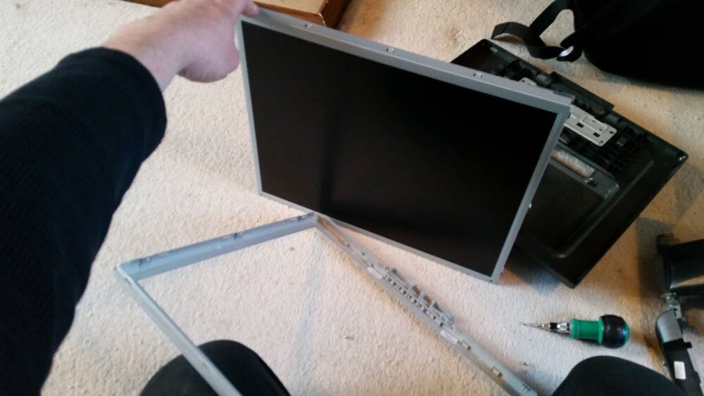
And by removing the bezel around the LCD, the screen will sit flush with the top of the table, and give you that essential minimalist finish.


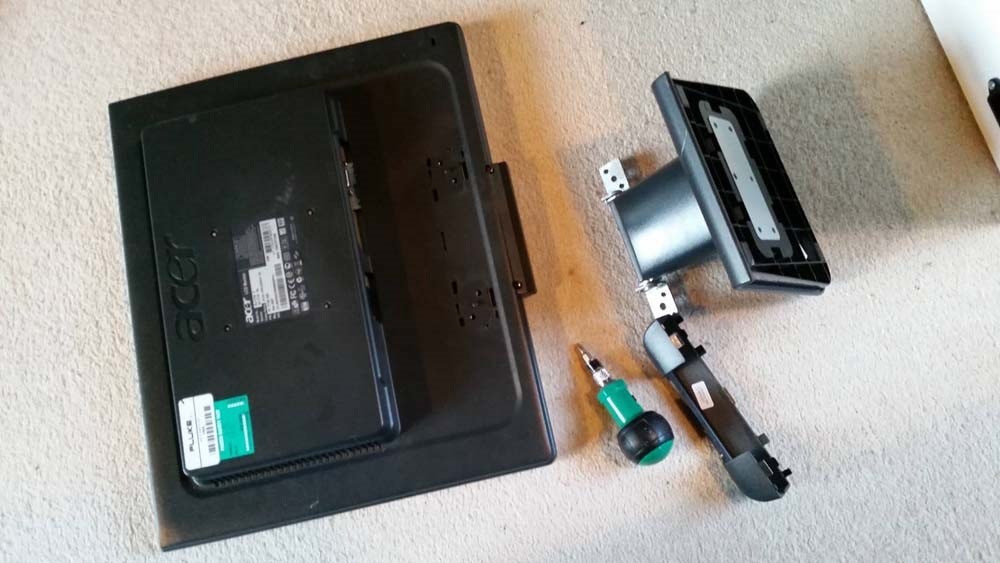
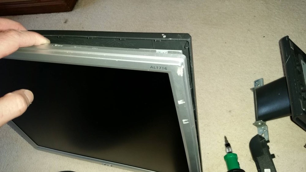
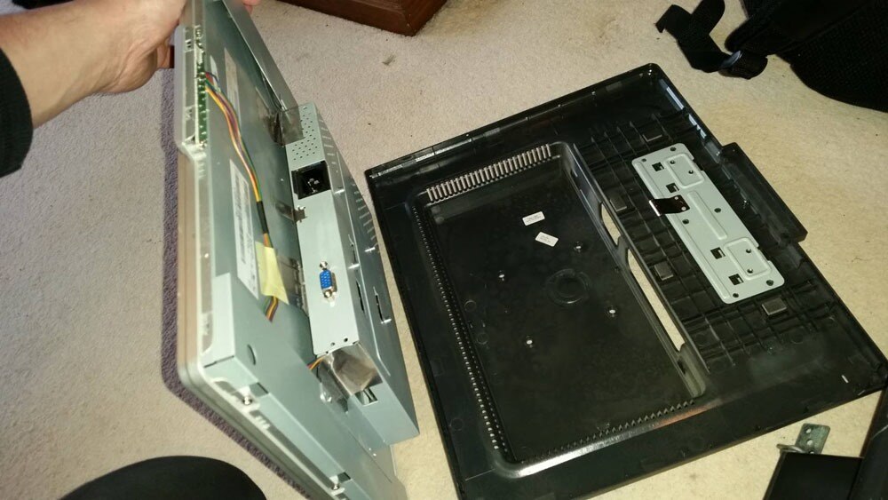
{gallery:autoplay=false} Removing the LCD from the Monitor Housing

Remove the stand, and any screws in the back of the monitor's housing.

image

It's probably all clipped together, so carefully pry the back of the housing away from the silver bezel around the screen.

image

You don't need to remove any of the shielding inside once the housing is apart. This is better left in place, to protect the back of the LCD. Note that you might need to relocate (and protect/insulate) the small PCB with the monitor's buttons on.

image

Remove any small screws that fix the bezel to the LCD's shielding.

image

Leaving you with an LCD panel that'll sit nice and flush to the table top.

image


Screen Mounting

The first time out we used a Dremel with a router attachment to cut the hole in the table top for the monitor, which actually worked very nicely. However, these ultra-cheap tables really don't warrant that much power tool action, when a Stanley knife does the job just as easily and with a lot less mess. The choice is yours, of course.


Below you can see how we drew around the screen to get the sizing for the hole, and then drilled 13mm holes in each corner to give the cut-out some nice, radius corners.


Clamp a straight edge along the outside of the line you want to cut, and repeatedly run the knife along it. Remember not to cut all the way into the hole on the opposite side from where you started. Chances are the knife will continue and make a mess of the nice radius you put in there. Instead, stop 10cm short and cut again from the other end.


Go around all four sides (it won't take a lot of effort) and prize out the cut-out piece. It won't just come free, as it's glued to the structural filling inside the table, so take care when prizing it up so as not to damage the surface of the table. Run a knife around the honeycomb paper filling, and pull it out. You now have a hole to drop the monitor in.


{gallery:autoplay=false} Mounting the Screen in the Table

Lay the dismantled monitor on the table and draw around it. I also put the joystick and buttons roughly in place, to help locate the monitor in its ideal position.

image

Use the drill bit for the corners to mark where to drill. This'll give you nice, rounded corners on the cut out.

image

Drill the four corner holes for the cut out.

image

Mask off the area around the hold, to protect the surface of the table when you clamp a straight edge to it.

image

Clamp a straight edge to the outside of the cut out (so if you slip, the damage will be on the piece you're removing), and make lots of gentler cuts from one hole along the straight edge, stopping short of the second hole. Cut from the second hole, back along the same line to prevent the knife from slipping and damaging the radius of the second hole.

image

When you've cut right through the table top on all four sides, carefully pry the cut out up. It'll be stuck to the innards of the table, but will come free with a little effort. Save the cut out for later on.

image

Run a knife around the honeycomb and rip it out.

image

You've a nice, neat, monitor-shaped hole in the table!

image

If it's all gone well, take a moment to feel a little smug about yourself.

image


Control Mounting

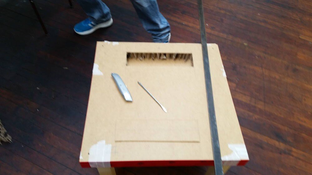
Flip the table top over and cut a letter box into the back. This gives you access to the inside-back of the table top so you can mount the joystick and buttons. Cut it out the same way as before and remove the honeycomb.


Mark where you want to mount your joystick and buttons -- we went with four buttons -- and drill 28mm holes for each one. This is the standard size for arcade buttons, and also gives the joystick plenty of room to move without the hole being visible around the round, flat cover that comes with the joystick.


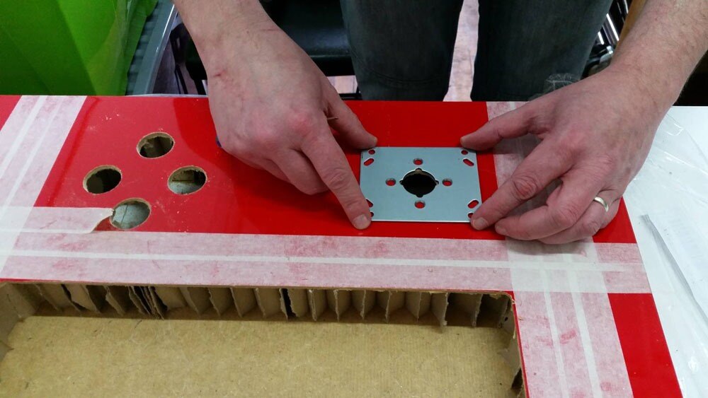
But we didn't want any fixings visible on the PIK3A table top, which meant we couldn't use the mounting holes in the joystick's plate. Instead, we removed the mounting plate and used the screws that attach it to the body of the joystick (where the microswitches are) to fix the joystick in place. They're a little bit short, but when you countersink the holes in the table top, they'll still reach and grab hold of the thread solidly.


You'll need to remove the mounting plate's screws and the ball top, and then offer the joystick up from underneath the table. It's a little tricky, as the plate will be loose when you're inserting the joystick into the table, but it's not too hard. When it's in place, replace the mounting plate's screws when passing them through the table top, put the round cover over the stick, put the ball top back on, and you've fixed the joystick in place without any visible screws.


The buttons are a simple matter -- drill the 28mm hole, and put the nut on the back of the button! We went with a diamond arrangement for the buttons, plus a start button and coin button on the side of the table top.


{gallery:autoplay=false} Mounting the Controls

I was a bit rougher cutting the access panel in the back, as it's not as visible as the table top. So mark it up, and cut out the minimum that you need (to help maintain the table's already waning stability).

image

The access panel cut out.

image

Mark where you want your buttons and joystick (including those on the edge for coin and start), and drill 28mm holes for each one.

image

Remove the mounting plate from the joystick. These are the mounting holes you'll use to hold the joystick in place.

image

Use the mounting plate to mark the four holes just around the centre. You'll also need to countersink these holes so the screw heads sit flush.

image

Remove the ball top from the joystick, hold the mounting plate in place underneath and screw the joystick in place from above.

image

Put the round cover over the joystick and screw the ball top back in place. And you can now fix all the buttons in place, too.

image


Control Interface

Arcade controls are actually very simple. Even the joysticks are effectively just normally open push buttons (one for each of the four directions). The thing is, computers like the Raspberry Pi don't generally accept such simple buttons as a controller! So we've opted for an Arduino Leonardo as a way to interface the arcade controls with the Raspberry Pi (moreover, the video game emulators the Pi will be running), as it can be set to identify itself to the computer/Raspberry Pi as a standard keyboard.


So each button is connected into one of the Leonardo's inputs, which translates them into keyboard key presses. A ground wire loops around the other side of each microswitch. Because we love the old coin-ops, we set ours up using the standard keyboard controls for MAME. You don't have to do this, but it'll save you a job if you do it this way.


image


Download and install the Arduino IDE, if you haven't already, and plug in your Leonardo to your computer via a USB cable. Below is the code we hammered together that translates the joystick and buttons into key presses (using the MAME standards, as previously mentioned). But coders we ain't, so if you can improve on this sketch, please post it in the comments.


Before that, here's what to do if you've never played with Arduino before (skip ahead if you know how to upload the sketch to your Leonardo).

    • A "sketch" is a program that your Leonardo will run after it's been uploaded. You can copy and paste the code below into the Arduino IDE window, or download the attached sketch file and open it using the IDE window. It's the same code, but take your pick of how to get onto the Arduino.
    • Take a read through, and you'll see how each input relates to a specific keyboard key press. You can make any desired changes here before uploading to the Leonardo.
    • Click the "Tools" menu and select "Arduino Leonardo" from the "Board" option.
    • Click "Tools" again, and select your Leonardo from the list in the "Ports" option. It's now ready for uploading your sketch.
    • Click the "Upload" button (a circular button with a right-facing arrow in it) to upload the sketch, and the Leonardo is ready to rock.


Sketch Code:

//element14 PIK3A Gaming Table Controls, using an Arduino Leonardo//

void setup() {
  Keyboard.begin();


  //Joystick and buttons pin allocations
  pinMode(0, INPUT_PULLUP); //Joystick Up
  pinMode(1, INPUT_PULLUP); //Joystick Down
  pinMode(2, INPUT_PULLUP); //Joystick Left
  pinMode(3, INPUT_PULLUP); //Joystick Right
  pinMode(4, INPUT_PULLUP); //Button 1
  pinMode(5, INPUT_PULLUP); //Button 2
  pinMode(6, INPUT_PULLUP); //Button 3
  pinMode(7, INPUT_PULLUP); //Button 4
  pinMode(8, INPUT_PULLUP); //Coin
  pinMode(9, INPUT_PULLUP); //Start
}


void loop() {


  // Button labels:
  int joystickUp = digitalRead(0);
  int joystickDown = digitalRead(1);
  int joystickLeft = digitalRead(2);
  int joystickRight = digitalRead(3);
  int button1 = digitalRead(4);
  int button2 = digitalRead(5);
  int button3 = digitalRead(6);
  int button4 = digitalRead(7);
  int coin = digitalRead(8);
  int start = digitalRead(9);


  // Joystick Up - Arrow Up Key
  if (joystickUp == LOW) {
    Keyboard.press(218);
  }
  else {
    Keyboard.release(218);
  }


  // Joystick Down - Arrow Down Key
  if (joystickDown == LOW) {
    Keyboard.press(217);
  }
  else {
    Keyboard.release(217);
  }


  // Joystick Left - Arrow Left Key
  if (joystickLeft == LOW) {
    Keyboard.press(216);
  }
  else {
    Keyboard.release(216);
  }


  // Joystick Right - Arrow Right Key
  if (joystickRight == LOW) {
    Keyboard.press(215);
  }
  else {
    Keyboard.release(215);
  }


  // Button 1 - Left CTRL
  if (button1 == LOW) {
    Keyboard.press(128);
  }
  else {
    Keyboard.release(128);
  }


  // Button 2 - Left ALT
  if (button2 == LOW) {
    Keyboard.press(130);
  }
  else {
    Keyboard.release(130);
  }


  // Button 3 - Left CTRL
  if (button3 == LOW) {
    Keyboard.press(32);
  }
  else {
    Keyboard.release(32);
  }


  // Button 4 - Left CTRL
  if (button4 == LOW) {
    Keyboard.press(129);
  }
  else {
    Keyboard.release(129);
  }


  // Coin - 5
  if (coin == LOW) {
    Keyboard.press(53);
  }
  else {
    Keyboard.release(53);
  }


  // Start - 1
  if (start == LOW) {
    Keyboard.press(49); delay(100);
  }
  else {
    Keyboard.release(49);
  }
  
}


Audio

These cube-shaped USB speakers from CPC were perfect for this job. Admittedly, you're about to void the warranty, but they're not expensive image


What's great about them is that they're powered externally, so you get better volume, they're small, and the volume control is beautifully low profile; we're going to transplant that onto the edge of the PIK3A's table top next to the start and coin buttons. The speakers themselves are mounted inside the table, pointing downwards (so the grille holes aren't visible from the top).


There's nothing fancy about this task. Dismantle the speakers, desolder and then resolder each cable in turn so you can remove the speaker housings. You'll also need to extend the wires for the right speaker, as they're very short on account of being in the same housing as the volume control board. The 3.5mm jack goes into the Pi's audio output.


Fix the speakers inside the table on either side of the access hole for the joystick and buttons, and drill a 10mm hole in the front edge of the table for the volume control potentiometer. We then used heat glue to keep the volume control board in place.


{gallery:autoplay=false} Dismantling and Installing the Speakers

Unscrew the front of the speakers and remove the volume control. You'll need to pry the dial off the back and unscrew the nut holding it in place.

image

Desolder and reattach the various cables (one at a time, ideally) from the volume control board so you can remove the cube-shaped housings. Extend the wires for the right speaker, too.

image

Drill a mounting hole in the edge of the table to relocate the volume control.

image

Mark the mounting holes for the speakers on either side of the rear access panel.

image

Drill a few holes for the sound to get out, and then you can fix the speakers in place and the volume control in place. It's probably easier to do it before the joystick and buttons are in place.

image


Power

There wasn't really much room left to embed a mains extension inside the table. We cut a connector into the bottom, and wired the extension lead into that. This way we can add a longer power cable if required, or even use one for different regions should the PIK3A table find itself going abroad.


We've powered the speakers and Pi separately, just to spread the load out a bit, but to be honest the Pi3 could handle the speakers from its USB ports. The choice is yours, here.


The monitor, Pi3 and speakers are all connected into the mains extension, powering everything up while hiding the connections beneath the table.

{gallery:autoplay=false} Powering all the Parts

Mark a square in the back corner underneath the table and cut a hole for the power connector. The mains extension is going to connect to the rear of this IEC connector.

image

Remove the plug from the back of the mains extensions, feed the cable through the inside of the table and bring it out of the hole for the IEC connector. You can now solder the wires to the reverse of the IEC connector, and fit it in place.

image

It doesn't hurt to screw the mains extension to the bottom of the table, too. In my experience, they tend to fall off the eyelet holes if there's a light breeze, so this one is screwed in place from inside.

You can plug the monitor and a couple of USB adapters into this, to power the screen, Raspberry Pi and speakers, while only requiring one power cable.

image

Finishing Touches

The monitor is a bit vulnerable here, so we decided to get a piece of 3mm acrylic cut to the same size as the table top (550mm by 550mm). It's just screwed into the table top in each corner, and the screws hidden behind screw caps. It's a cheap way to keep things protected.


I also added a panel mount USB port next to the access panel underneath, just in case I ever need to plug a USB keyboard (or other peripheral -- it could be a joypad if you wanted) into the Pi3.


{gallery:autoplay=false} Finishing Touches

An external USB port that goes into the Pi. This is a good one, as it also has a dust cap, since this probably isn't going to get a lot of use.

image

If you decide to put an acrylic or polycarbonate sheet on top to protect the monitor, remember to put it in place before you insert the buttons, as they'll need to pass through the sheet.

Here we've screwed it in place in each corner, and covered the screw heads with caps.

image

Remember how you saved the cut out from the monitor hole? Trim it down to make a cover for the access panel on the back, after notching the bottom of the table as an exit for the power cables.

image

The finished PIK3A table is strong enough to hold Baxter here, but given how much we've hollowed it out, be careful about how much weight you put on it. Definitely don't stand on it to change a light bulb (mind you, I wouldn't trust these enough do that with a new Ikea table).

image


Then it's just a case of screwing the legs to the table top, and installing RetroPie on the SD card. There's one additional step you might have to perform for the time being, to get RetroPie running in the Raspberry Pi 3. The developers will undoubtedly fix things very soon, but for the moment we had to copy over the "*.elf" files (that'd be imagestart.elf, start_cd.elf, start_db.elf and start_x.elf) from the "Boot" partition of an SD card that had the official, Raspberry Pi NOOBs image.


Not a complex or particularly onerous task, but a necessary one for the time being. This should get RetroPie booted up and running beautifully on your awesome new PIK3A retro gaming table. I'm sure it won't be long at all before this step becomes unnecessary, of course -- likely by the time you've built your cab.


UPDATE: The RetroPie guys have already released an updated image, so you don't have to jump through any hoops to get RetroPie working on your Raspberry Pi 3! Great work, guys!

http://blog.petrockblock.com/2016/03/02/retropie-3-6-is-released/


As you can see, this is a pretty fascinating interpretation of the classic gaming system, so we'd be particularly interested in seeing how you might do the same, as much as copy our build part for part. Post your own retro gaming projects right here in the Raspberry Pi Projects sections, and casually blow our minds!


If you want to see them in action right away, join us as we head out and about on the Raspberry Pi 3's launch day in Leeds and Chicago!


And if you're looking to delve a little deeper into the Raspberry Pi 3, why not sign up for our RoadTest right now and review the unit for the world to see?

Supporting Downloads/Files

-  PIK3A Supporting Files 
image NEW! Raspberry Pi 3 Model B
Frequently Asked Questions Comparison Chart Technical Specifications
Unboxing Video 40 Pin Out
  • fruitful_three
  • retro gaming
  • raspberry pi arcade cabinet
  • picade
  • pi3
  • pik3a
  • gaming
  • raspberry pi 3
  • raspberry_pi_projects
  • pikea
  • video games
  • Share
  • History
  • More
  • Cancel
  • Sign in to reply

Top Comments

  • e14 Contributor
    e14 Contributor over 10 years ago +13
    Mine is pretty much done! Still waiting for a usb extension for the external usb port, and an IEC connector for a nice finished power input. I used some black electrical tape to give the screen a nice…
  • badvs3vil
    badvs3vil over 10 years ago +8
    I will post more later once I have everything working, but here is what mine looks like so far. I also installed an HDMI splitter and just like the external USB that Spencer used in his but mine also has…
  • kravex
    kravex over 10 years ago +8
    Finished at last! I never got the HDMI splitter to work correctly, it seemed to only want to work if both the TV and monitor were on and plugged in, I even locked down the monitor res in config.txt but…
  • e14 Contributor
    e14 Contributor over 10 years ago in reply to jtanner

    No, I still have the issues, but I haven't had much time to mess with it this week.  I'm going to get back into it this weekend.  And that sounds like something that is definitely causing part of my Problems!


    My player 2 direction controls were all lower case letters, and shift was one of player 1 buttons!


    I need to do a major review of code and wiring tomorrow. 


    Do you know if there is any difference between the 3 GRD (ground)  pins on the arduino?


    Thanks!

    Scott

    • Cancel
    • Vote Up 0 Vote Down
    • Sign in to reply
    • More
    • Cancel
  • jtanner
    jtanner over 10 years ago in reply to e14 Contributor

    Scott: Have you resolved your issues yet? I also discovered (And I've yet to post the update here) that the Leonardo uses unicode keycodes.  Which means that lowercase & uppercase have unique codes (Which also explains the need for custom modifiers for Function (F1,F2,F3....) keys etc.  If for example you send keyboard.write(80) (The letter p) - but in unicode 80 is Uppercase!.  The arduino ACTUALLY sends press Shift + P, which results in SHIFT being detected as the last pressed key and not P.  Lowercase p is keyboard.write(112);  (I have a pause button for use in mame on mine)

    • Cancel
    • Vote Up 0 Vote Down
    • Sign in to reply
    • More
    • Cancel
  • e14 Contributor
    e14 Contributor over 10 years ago in reply to rokster

    I used the "Amazon Basics" set.  Came apart pretty easily, but the threaded neck on the pot was too short to go through the table anywhere.  I had to reuse the speaker shell from oneach of the speakers to make a housing for the volume control.  I will grab a pic this weekend when I get back into this project.

    • Cancel
    • Vote Up +1 Vote Down
    • Sign in to reply
    • More
    • Cancel
  • e14 Contributor
    e14 Contributor over 10 years ago in reply to jtanner

    Yea, I'm not sure how that happened :/

    • Cancel
    • Vote Up 0 Vote Down
    • Sign in to reply
    • More
    • Cancel
  • jtanner
    jtanner over 10 years ago in reply to rokster

    What speakers did you get? Can you provide a link? I tried both the Arctic one mentioned in this tutorial, as well as some other £3 speakers from eBay.  The Arctic ones just took some brute force, wedging a screwdriver in the side and forcing up the edge.  I repeated this at various points around the edge and eventually it popped off.  Underneath the knob of the arctic set is a nut on the pot shaft keeping it in place.


    The eBay ones I got from here: USB Portable Computer Laptop Speakers System Multimedia Desktop PC Speaker MAC | eBay Pretty good for £2.95 although don't expect them to be amazing - the Arctic for example gives a better, louder sound but for again for the price, they're great.  Plus side is the volume control comes out much easier as it's a wheel edge instead of the entire dial on the outside (hard to explain but get some, and you'll know what I mean)

    • Cancel
    • Vote Up +1 Vote Down
    • Sign in to reply
    • More
    • Cancel
  • rokster
    rokster over 10 years ago

    Is there a trick to dismantling PC speakers? My last pair were easy until it came to removing the volume knob. It was firmly connected to the pot on the circuit board and wouldn't pull through the casing. I ended up using too much force and decapitating it. I've now bought a cheap set from Maplin to have another go and am finding the same thing. The power button comes through the case when all the screws are removed. Everything comes apart easily except for the volume knob which, again, seems firmly attached to the pot and won't pull through the casing.

    • Cancel
    • Vote Up 0 Vote Down
    • Sign in to reply
    • More
    • Cancel
  • jtanner
    jtanner over 10 years ago

    spannerspencer


    FYI - in your code, you have:


    1.   // Button 3 - Left CTRL 
    2.   if (button3 == LOW) { 
    3.     Keyboard.press(32); 
    4.   } 
    5.   else { 
    6.     Keyboard.release(32); 
    7.   } 
    8.  
    9.  
    10.   // Button 4 - Left CTRL 
    11.   if (button4 == LOW) { 
    12.     Keyboard.press(129); 
    13.   } 
    14.   else { 
    15.     Keyboard.release(129); 
    16.   } 


    32 = Spacebar

    129 = Left Shift


    (Only pointing this out so those "newer" to coding don't get confused image)


    Also, someone else also posted some improved code.... here's my take on a neater way of doing things (I'm OCD too, I like minimalistic code! )


    #include <Keyboard.h>


    #define BUTTONS 15

    int pin_arr[]={A0,A1,A2,A3,2,3,4,5,6,7,8,9,10,A5,A4};

    int keycode_arr[]={218,217,216,215,128,130,32,90,88,176,53,49,80,177,179};

    // UP,DOWN,LEFT,RIGHT,LEFT-CTRL (Button 1), LEFT-ALT (Button 2),SPACEBAR (Button 3), LEFT-SHIFT (Button 4), Z (Button 5), X (Button 6), Coin/Credit, 1P Start, P (Pause), ESC, TAB

    int key_state[BUTTONS];


    void setup() {

      Keyboard.begin();

      for (int i=0;i<BUTTONS;i++)

      {

        pinMode(pin_arr[i], INPUT_PULLUP);

        key_state[i] = digitalRead(pin_arr[i]);

      }

    }


    void loop() {

      for (int i=0;i<BUTTONS;i++)

      {

        key_state[i]=digitalRead(pin_arr[i]);

        if (key_state[i]==LOW) {

          Keyboard.press(keycode_arr[i]); if (keycode_arr[i] == 49) { delay(100); }

        } else {

          Keyboard.release(keycode_arr[i]);

        }

      } 

    }

    Feel free to add it as an alternative if you'd like.


    And for "reference" since  a few have asked before, and will hopefully prove of use to others, here are numerous keyboard keycodes...


    /*

    Keyboard Keycodes listed below.  For reference, you can visit the 2 sites listed below:


    For a list of the Arduino Specific Key modifiers, visit: https://www.arduino.cc/en/Reference/KeyboardModifiers

    For all other Keyboard codes, visit this page for an interactive key code map: http://www.cambiaresearch.com/articles/15/javascript-key-codes


           Arduino Key Modifiers                            STANDARD KEYBOARD KEY CODE MAP

        Key                   Code                             Key                  Code

    ------------------------------------                  ------------------------------------

      KEY_LEFT_CTRL           128                             backspace               8

      KEY_LEFT_SHIFT          129                             tab                     9

      KEY_LEFT_ALT            130                             enter                   13

      KEY_LEFT_GUI            131                             shift                   16

      KEY_RIGHT_CTRL          132                             ctrl                    17

      KEY_RIGHT_SHIFT         133                             alt                     18

      KEY_RIGHT_ALT           134                             pause/break             19

      KEY_RIGHT_GUI           135                             caps lock               20

      KEY_UP_ARROW            218                             escape                  27

      KEY_DOWN_ARROW          217                             page up                 33

      KEY_LEFT_ARROW          216                             page down               34

      KEY_RIGHT_ARROW         215                             end                     35

      KEY_BACKSPACE           178                             home                    36

      KEY_TAB                 179                             left arrow              37

      KEY_RETURN              176                             up arrow                38

      KEY_ESC                 177                             right arrow             39

      KEY_INSERT              209                             down arrow              40

      KEY_DELETE              212                             insert                  45

      KEY_PAGE_UP             211                             delete                  46

      KEY_PAGE_DOWN           214                             0                       48

      KEY_HOME                210                             1                       49

      KEY_END                 213                             2                       50

      KEY_CAPS_LOCK           193                             3                       51

      KEY_F1                  194                             4                       52

      KEY_F2                  195                             5                       53

      KEY_F3                  196                             6                       54

      KEY_F4                  197                             7                       55

      KEY_F5                  198                             8                       56

      KEY_F6                  199                             9                       57

      KEY_F7                  200                             a                       65

      KEY_F8                  201                             b                       66

      KEY_F9                  202                             c                       67

      KEY_F10                 203                             d                       68

      KEY_F11                 204                             e                       69

      KEY_F12                 205                             f                       70

                                                              g                       71

                                                              h                       72

                                                              i                       73

                                                              j                       74

                                                              k                       75

                                                              l                       76

                                                              m                       77

                                                              n                       78

                                                              o                       79

                                                              p                       80

                                                              q                       81

                                                              r                       82

                                                              s                       83

                                                              t                       84

                                                              u                       85

                                                              v                       86

                                                              w                       87

                                                              x                       88

                                                              y                       89

                                                              z                       90

                                                              left window key         91

                                                              right window key        92

                                                              select key              93

                                                              numpad 0                96

                                                              numpad 1                97

                                                              numpad 2                98

                                                              numpad 3                99

                                                              numpad 4                100

                                                              numpad 5                101

                                                              numpad 6                102

                                                              numpad 7                103

                                                              numpad 8                104

                                                              numpad 9                105

                                                              multiply                106

                                                              add                     107

                                                              subtract                109

                                                              decimal point           110

                                                              divide                  111

                                                              F1                      112

                                                              F2                      113

                                                              F3                      114

                                                              F4                      115

                                                              F5                      116

                                                              F6                      117

                                                              F7                      118

                                                              F8                      119

                                                              F9                      120

                                                              F10                     121

                                                              F11                     122

                                                              F12                     123

                                                              num lock                144

                                                              scroll lock             145

                                                              semi-colon              186

                                                              equal sign              187

                                                              comma                   188

                                                              dash                    189

                                                              period                  190

                                                              forward slash           191

                                                              grave accent            192

                                                              open bracket            219

                                                              back slash              220

                                                              close braket            221

                                                              single quote            222

                                                              spacebar                32

    */

    (Taken from my own project.  I added this info in Keycodes.h which isn't actually included in the compiled code, it's just in the project for reference)

    • Cancel
    • Vote Up 0 Vote Down
    • Sign in to reply
    • More
    • Cancel
  • jtanner
    jtanner over 10 years ago in reply to kravex

    Ah! I may consider adding it at a later date, but primarily the idea is be a 2 player coffee table with the monitors built in still image But thanks for the link, I've added it to my eBay watch lists as it could still prove handy

    • Cancel
    • Vote Up 0 Vote Down
    • Sign in to reply
    • More
    • Cancel
  • kravex
    kravex over 10 years ago in reply to jtanner

    I removed it when I noticed you were using VGA connectors and realised it would need adaptors and increase the price, it's more useful for connecting an external HDMI if you want that as an optional extra image. You may want to look at a powered splitter for either option though as non-powered VGA splitters seem to loose some brightness which is crucial with these viewing angles.

    • Cancel
    • Vote Up +1 Vote Down
    • Sign in to reply
    • More
    • Cancel
  • jtanner
    jtanner over 10 years ago

    Not sure if "Kravex" / Alan Clarke removed his comment as it's not showing for me (I read it from my email) he said:


    HDMI Splitter that runs on USB power: http://www.ebay.co.uk/itm/131327456247?_trksid=p2060353.m1438.l2649&ssPageName=STRK%3AMEBIDX%3AIT £7.95 UK stock.


    That's a great idea, and if my current plan doesn't work out, I will look into it.  My method, is cheaper since I'm only using 1 HDMI > VGA (HDMI TO VGA CONVERTER ADAPTER WITH AUDIO | RASPBERRY PI | AMAZON FIRE TV STICK | eBay at £5.49 and then Monitor VGA SVGA Y Dual Splitter Cable Lead - SENT TODAY | eBay  at £4.69.   (Total: £10.18)


    If I did it the way Kravex suggested, it would be 2 x HDMI > VGA adapters (£11.98) + the linked HDMI Splitter (£7.95) totalling £19.93 which is almost double.  Plus it would use up a crucial USB port (trying to avoid needing a hub). Although that may still have to be the required route so I've added to my eBay watch list... I will keep those interested updated as items arrive image

    • Cancel
    • Vote Up 0 Vote Down
    • Sign in to reply
    • More
    • Cancel
<>
element14 Community

element14 is the first online community specifically for engineers. Connect with your peers and get expert answers to your questions.

  • Members
  • Learn
  • Technologies
  • Challenges & Projects
  • Products
  • Store
  • About Us
  • Feedback & Support
  • FAQs
  • Terms of Use
  • Privacy Policy
  • Legal and Copyright Notices
  • Sitemap
  • Cookies

An Avnet Company © 2026 Premier Farnell Limited. All Rights Reserved.

Premier Farnell Ltd, registered in England and Wales (no 00876412), registered office: Farnell House, Forge Lane, Leeds LS12 2NE.

Follow element14

  • X
  • Facebook
  • linkedin
  • YouTube