element14 Community
element14 Community
    Register Log In
  • Site
  • Search
  • Log In Register
  • Community Hub
    Community Hub
    • What's New on element14
    • Feedback and Support
    • Benefits of Membership
    • Personal Blogs
    • Members Area
    • Achievement Levels
  • Learn
    Learn
    • Ask an Expert
    • eBooks
    • element14 presents
    • Learning Center
    • Tech Spotlight
    • STEM Academy
    • Webinars, Training and Events
    • Learning Groups
  • Technologies
    Technologies
    • 3D Printing
    • FPGA
    • Industrial Automation
    • Internet of Things
    • Power & Energy
    • Sensors
    • Technology Groups
  • Challenges & Projects
    Challenges & Projects
    • Design Challenges
    • element14 presents Projects
    • Project14
    • Arduino Projects
    • Raspberry Pi Projects
    • Project Groups
  • Products
    Products
    • Arduino
    • Avnet & Tria Boards Community
    • Dev Tools
    • Manufacturers
    • Multicomp Pro
    • Product Groups
    • Raspberry Pi
    • RoadTests & Reviews
  • About Us
    About the element14 Community
  • Store
    Store
    • Visit Your Store
    • Choose another store...
      • Europe
      •  Austria (German)
      •  Belgium (Dutch, French)
      •  Bulgaria (Bulgarian)
      •  Czech Republic (Czech)
      •  Denmark (Danish)
      •  Estonia (Estonian)
      •  Finland (Finnish)
      •  France (French)
      •  Germany (German)
      •  Hungary (Hungarian)
      •  Ireland
      •  Israel
      •  Italy (Italian)
      •  Latvia (Latvian)
      •  
      •  Lithuania (Lithuanian)
      •  Netherlands (Dutch)
      •  Norway (Norwegian)
      •  Poland (Polish)
      •  Portugal (Portuguese)
      •  Romania (Romanian)
      •  Russia (Russian)
      •  Slovakia (Slovak)
      •  Slovenia (Slovenian)
      •  Spain (Spanish)
      •  Sweden (Swedish)
      •  Switzerland(German, French)
      •  Turkey (Turkish)
      •  United Kingdom
      • Asia Pacific
      •  Australia
      •  China
      •  Hong Kong
      •  India
      •  Japan
      •  Korea (Korean)
      •  Malaysia
      •  New Zealand
      •  Philippines
      •  Singapore
      •  Taiwan
      •  Thailand (Thai)
      •  Vietnam
      • Americas
      •  Brazil (Portuguese)
      •  Canada
      •  Mexico (Spanish)
      •  United States
      Can't find the country/region you're looking for? Visit our export site or find a local distributor.
  • Translate
  • Profile
  • Settings
RoadTests & Reviews
  • Products
  • More
RoadTests & Reviews
Review Blogs TMC2300-IOT-REF - Remote controlled Stepper Motor - Getting your motor running
  • Blogs
  • Forum
  • Documents
  • RoadTests
  • Reviews
  • Polls
  • Files
  • Members
  • Sub-Groups
  • More
  • Cancel
  • New
Join RoadTests & Reviews to participate - click to join for free!
  • Share
  • More
  • Cancel
  • Author Author: Workshopshed
  • Date Created: 7 Feb 2021 8:31 AM Date Created
  • Views 6339 views
  • Likes 11 likes
  • Comments 35 comments
Related
Recommended

TMC2300-IOT-REF - Remote controlled Stepper Motor - Getting your motor running

Workshopshed
Workshopshed
7 Feb 2021

As mentioned in the last post TMC2300-IOT-REF - Remote controlled Stepper Motor - Getting to blink there was an issue with the connector on the motor. I found a grove connector was about the right size if I trimmed it slightly so I soldered that on.


Get your motor running

The next thing to try is to have the motor running. For this there are a few steps needed. Firstly to provide some power then to send the right serial commands to the controller chip and the finally to enable motor output.


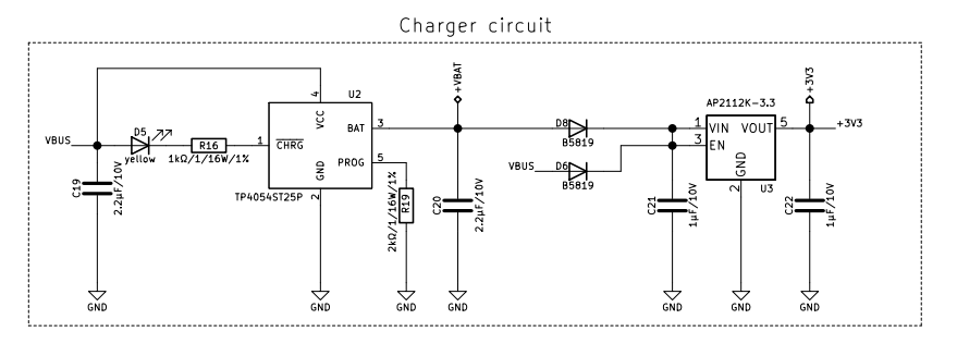
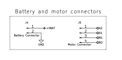
The supply to the motor is connected to +VBAT, this in turn is connected to the charger circuit. The AN058 tech note suggests you can use a power supply to power the motor.
 

image

Serial communication is covered in section 4 of the tmc3200 data sheet and Jan Cumps also did a detailed look at the serial comms for a previous road test, Trinamic Stepper Motor Controller TMC2300 - UART Interface  Jan also references a library which looks like it could be useful https://github.com/trinamic/TMC-API


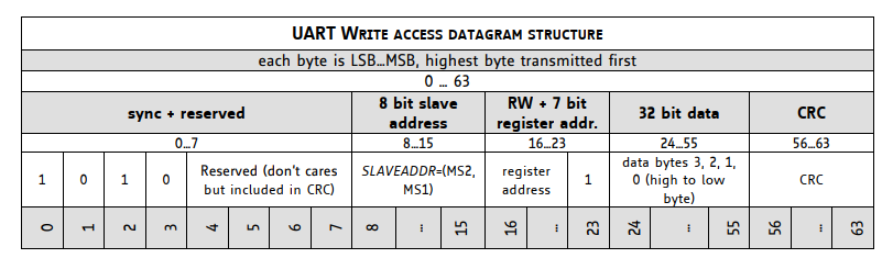
The key part of the serial communications is that the commands to send to the motor are wrapped in a special data structure for error checking and addressing. The address is configured via AD0 and AD1 pins, in this reference design these are both tied to ground so it would be address zero. The algorithm for the CRC is also included in the notes but the is a practical example for the code in the blynk example. https://github.com/trinamic/TMC2300-IOT-REF/blob/master/Blynk/Stepper_Mode
image

The enable pin can also be found in the schematic on pin 32 and this is confirmed by the code example.


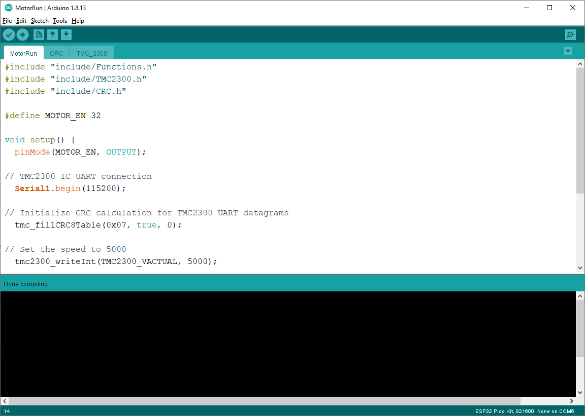
I copied in the TMC_2300.ino, CRC.ino and include files from the Blynk example. I was initially puzzled why the libraries were named with the INO suffix, but that allows the Arduino IDE to compile the files with the right headers so TMC_2300.ino can find Serial1 without needing to reference the Arduino header files. You just need to ensure you open the right ino to for your project. In my case "MotorRun.ino"
image

Checking the Blynk document we can see that the speed value is between 500 and 9000, and the current is between 9 and 31. So I plugged those values straight into the code.

#include "include/Functions.h"
#include "include/TMC2300.h"
#include "include/CRC.h"


#define LED_STATUS 18
#define MOTOR_EN 32


void setup() {
  pinMode(LED_STATUS, OUTPUT);
  pinMode(MOTOR_EN, OUTPUT);


// Debug console
  Serial.begin(115200);


// TMC2300 IC UART connection
  Serial1.begin(115200);


// Initialize CRC calculation for TMC2300 UART datagrams
  tmc_fillCRC8Table(0x07, true, 0);


// Set the speed to 7000
  tmc2300_writeInt(TMC2300_VACTUAL, 7000);


// Set the current limit to 31 (default)
  uint32_t value = 1 << TMC2300_IHOLDDELAY_SHIFT | ((31 << TMC2300_IRUN_SHIFT) & TMC2300_IRUN_MASK) | 8 << TMC2300_IHOLD_SHIFT;
                 
  tmc2300_writeInt(TMC2300_IHOLD_IRUN, value);


// Enable the motor
  digitalWrite(MOTOR_EN, HIGH);   


  Serial.print("Initialisation Complete");
}


void loop() {
    // Toggle the status LED while the motor is active
    digitalWrite(18, HIGH);
    delay(250);
    digitalWrite(18, LOW);
    delay(250);
    digitalWrite(18, HIGH);
    delay(250);
    digitalWrite(18, LOW);


  // Re-write the CHOPCONF register periodically
  tmc2300_writeInt(TMC2300_CHOPCONF, 0x14008001); 
}


The LED is still flashing nicely but no response from the motor. Possible causes include the motor wiring, power supply, Trinamic's code, my code.


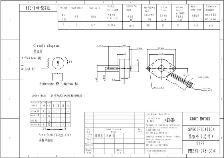
I cross checked the wiring and confirmed that there was one coil of the motor connected to pins 1 and 2 and the other to pins 3 and 4. However, looking at the datasheet in more detail vs the pinouts on the board, I spotted that the A coil was reversed, I'd still expect some kind of motion from the motor with that configuration but I swapped the connectors just to check. And still no motor movement.
imageimage

To check if power was an issue, I plugged in the board directly to a charger. Again, flashing lights but no motion. Looking at the schematic the diag pin is connected to a white led and would illuminate when there was a driver error or stall. This was not the case.


So my next thought was to use the serial interface to query the state of the chip and see if I could diagnose what was going on.


Serial Reading

Looking at the datasheet there were 3 registers that seemed of interest. GSTAT, GCONF and IOIN. So I updated the code to read these using the read int function and a simple display function


void printByte(uint8_t var) {
  for (uint8_t test = 0x80; test; test >>= 1) {
    Serial.write(var  & test ? '1' : '0');
  }
  Serial.println();
}


void loop() {
    delay(1000);
  
    result = tmc2300_readInt(TMC2300_GCONF);
    Serial.print("GCONF:");
    printByte(result);    


    result = tmc2300_readInt(TMC2300_GSTAT);
    Serial.print("GSTAT:");
    printByte(result);  


    result = tmc2300_readInt(TMC2300_IOIN);
    Serial.print("IOIN:");
    printByte(result);  
}


These all returned zero which made me suspect that it wasn't communicating with the TMC2300 correctly, but I double checked by adding IHOLD_IRUN and CHOPCONF which also came back as zero.

Next up I set the speed for the serial communication lower to 57600, that also made no difference.

One thing I didn't try was to see if there was an issue with the CRC. Looking at the code in TMC2300.INO there is a line that returns zero if the CRC does not tally. So that might be something to try.


Back to basics

Scouring the data sheet for the reference board, I spotted that the step and direction pins were connected to the ESP32. So I tried a simple sketch that pulsed the step pin and the motor did turn. However the motor got quite warm, quite quickly so I reflashed to a simple blink sketch.

So this does demonstrate that at least the motor is wired up correctly.

CAUTION: Do not simply pulse the step pin, that can overload the board.

At this point I decided to take a break as the board had got quite warm too.


Damaged?!

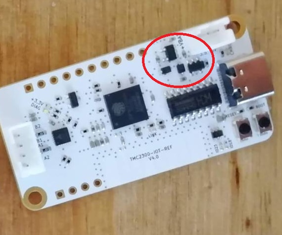
After leaving it an hour, I decided to try it again. If I power it up either from the battery or from USB the LED blinks so the ESP32 is obviously getting power. But the board is no longer detected as a serial port by the computer. The area ringed below gets very hot. One of the other roadtesters mentioned an under voltage condition which got me thinking that I may have just discharged the battery. So I checked that and the battery voltage seems a little high, am getting 3.9v on the connector on the edge of the board. The overheating happens regardless of if the battery is attachd or the USB or both. Also the the board is not recognise by the PC.


It is possible that this is caused by software e.g. the TMC2300 is still trying to draw a massive current on startup. Or it could be that the previous experiments damaged the battery charge/power regulation stage?
image

Backup Plan

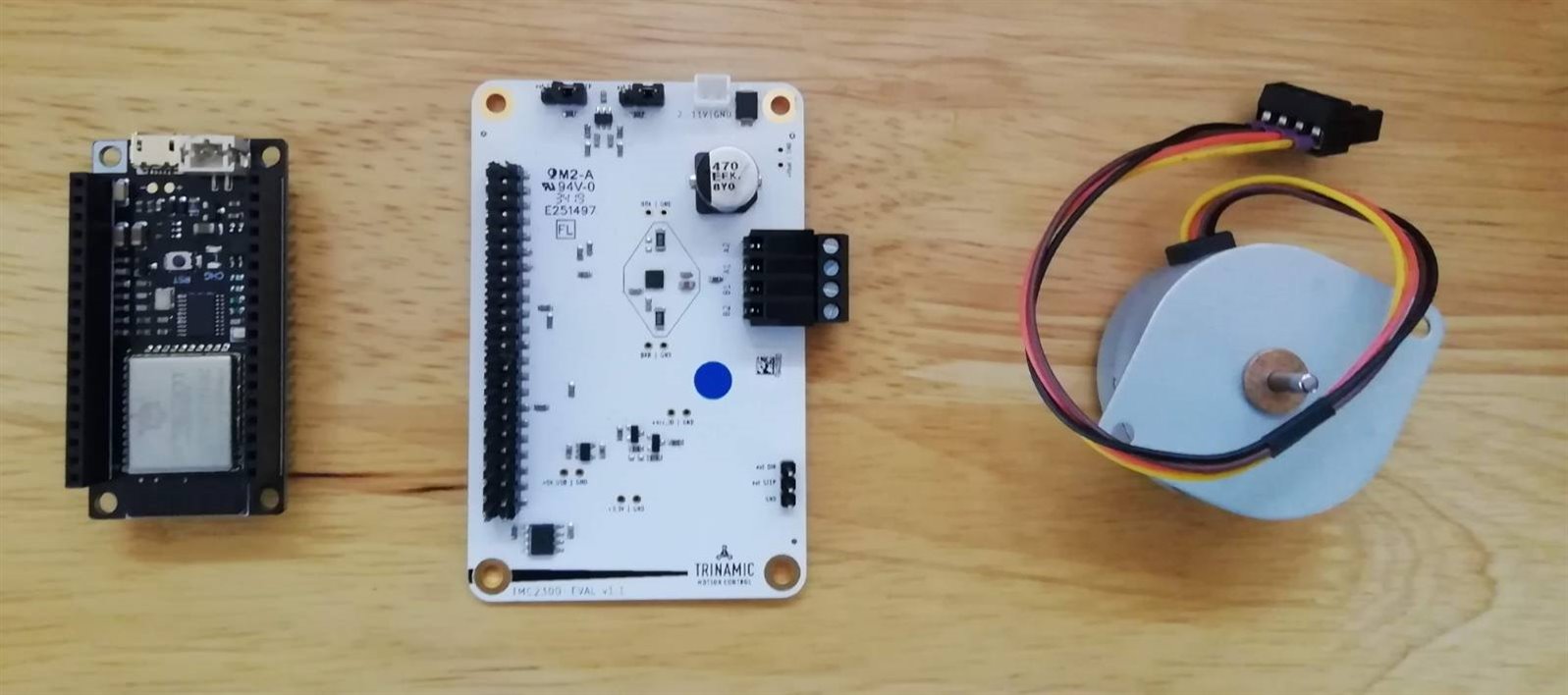
I've devised a backup plan. It might not look so similar but the combination of an off the shelf ESP32 module and the TMC2300 from a previous test should allow me to prove out the communication between the ESP32 and TMC2300. And the results from this should be reproduceable on the IOT reference design.
image

  • Sign in to reply

Top Comments

  • Gough Lui
    Gough Lui over 5 years ago +4
    Unfortunately, I don't have one of these boards, but if there is some schematic, that would usually be quite helpful. I haven't got the time to go and dig up documentation at this moment, but some basic…
  • Workshopshed
    Workshopshed over 5 years ago +4
    Gough Lui , trinamic_lisa thanks for to help. The 3.3v line is reading 3.3v when powered from battery. I think I have a USB isolator which should allow me to measure the current draw from the port. Gough…
  • Jan Cumps
    Jan Cumps over 5 years ago in reply to Gough Lui +4
    In lieu of a thermal camera, there is always the nose and finger. You can often smell what got hot after the facts (carbon or silicon burn smell). Or put some spit on your pinky and touch each component…
  • Workshopshed
    Workshopshed over 5 years ago in reply to navadeepganeshu

    Hi Navadeep, I believe I found the same diagram as you did and swapped the pins. You'll need to have the battery in place to run the motor.

    • Cancel
    • Vote Up +3 Vote Down
    • Sign in to reply
    • More
    • Cancel
  • navadeepganeshu
    navadeepganeshu over 5 years ago

    Had any luck with this thing?


    Looks like the motor to board connectors are not aligned and are alternative in order. Yellow - Red - Orange - Brown should be the right order as per numbering in the board.

    imageimage

    I tried the default order and by swapping it also. The motor is just making a buzzing sound when powered with USB only, Nothing with only battery(18650, 3.7V) and the TP4054ST25P(U2) gets overheated when powered with both USB and battery with no responses from the motor.


    Anything to do with firmware/ operating modes of TMC2300? I still doubtimage

    • Cancel
    • Vote Up +2 Vote Down
    • Sign in to reply
    • More
    • Cancel
  • trinamic_lisa
    trinamic_lisa over 5 years ago in reply to Workshopshed

    Workshopshed The IO5 pin needs to be pulled low to supply the TMC2300.

    • Cancel
    • Vote Up +2 Vote Down
    • Sign in to reply
    • More
    • Cancel
  • Workshopshed
    Workshopshed over 5 years ago in reply to Gough Lui

    Gough Lui I've been running the board without a motor connected since the problems started although it seems to make no difference if I connect that again. Next up checking that resistor Lisa mentioned and will see if I can probe some of the other components but they are a bit tiny.

    • Cancel
    • Vote Up +1 Vote Down
    • Sign in to reply
    • More
    • Cancel
  • Gough Lui
    Gough Lui over 5 years ago in reply to Workshopshed

    Hmm. An interesting result indeed that you were able to program with provision of power from VBAT but the unit is still getting hot (was that motor connected or disconnected?). I suspect this means when providing power from USB, you might just be tripping the port's overcurrent protection shutdown or some overtemperature shutdown on the linear regulator which is why the board doesn't connect. But the continued heating suggests you merely are providing enough power and whatever has failed has become a resistor (neither open or fully shorted). Thermal imaging or the "touch" test should narrow things down ...


    While the APK2112 is working, it doesn't really rule out anything downstream as it seems the current draw of the failure may be within its 600mA capabilities.


    If say D6 and D8 failed shorted or leaky, USB would flow directly to VBUS and potentially both draw a lot of current and pull the bus down. Or if the TP4054 is bad then it could be drawing excessive current from VBUS or VBAT (even though it shouldn't), but the TP4054 should be pretty much indestructible under normal circumstances. You're also right that ceramic capacitors could fail shorted - that usually happens with overvoltage (in my experience) and results in a nice "back spot of death". The TMC2300x failing is still a possibility too ... if it failed in a soft-shorted state drawing under 600mA total, the APK2112 should still stay regulated but be dissipating a decent amount of power. I suspect that you providing battery has a slight "benefit" to the APK2112 because now instead of dropping the difference between 5V and 3.3V, it would be anywhere from ~3.3 to 4.2V to 3.3V reducing the amount of dissipated power and heat so it may run longer.


    I feel there maybe a possibility that perhaps at some stage maybe reverse EMF from the motor or ESD may have contributed. Maybe the battery came loose from the connection in some way, reducing the ability to absorb transient spikes. Just my guess, but if you have a hot-air gun, maybe it's time to play "remove-the-component" to see when the current draw settles down. If you're sure there was smoke from the power section, perhaps taking out the TPS4054 will show if the issue was a faulted battery charger. But now I'm starting to think maybe the TMC2300x may have suffered too ... perhaps that's the next to remove since the ESP32 and APK2112 seem functional.


    - Gough

    • Cancel
    • Vote Up +3 Vote Down
    • Sign in to reply
    • More
    • Cancel
<>
element14 Community

element14 is the first online community specifically for engineers. Connect with your peers and get expert answers to your questions.

  • Members
  • Learn
  • Technologies
  • Challenges & Projects
  • Products
  • Store
  • About Us
  • Feedback & Support
  • FAQs
  • Terms of Use
  • Privacy Policy
  • Legal and Copyright Notices
  • Sitemap
  • Cookies

An Avnet Company © 2026 Premier Farnell Limited. All Rights Reserved.

Premier Farnell Ltd, registered in England and Wales (no 00876412), registered office: Farnell House, Forge Lane, Leeds LS12 2NE.

Follow element14

  • X
  • Facebook
  • linkedin
  • YouTube