


Hi All,
I have been moving on to testing the double pulse function within the AFG31052. To do this I purchased an EVAL6498LEVAL6498L board as used in the application note from Tektronix.
Below is the scribbled out setup I created.
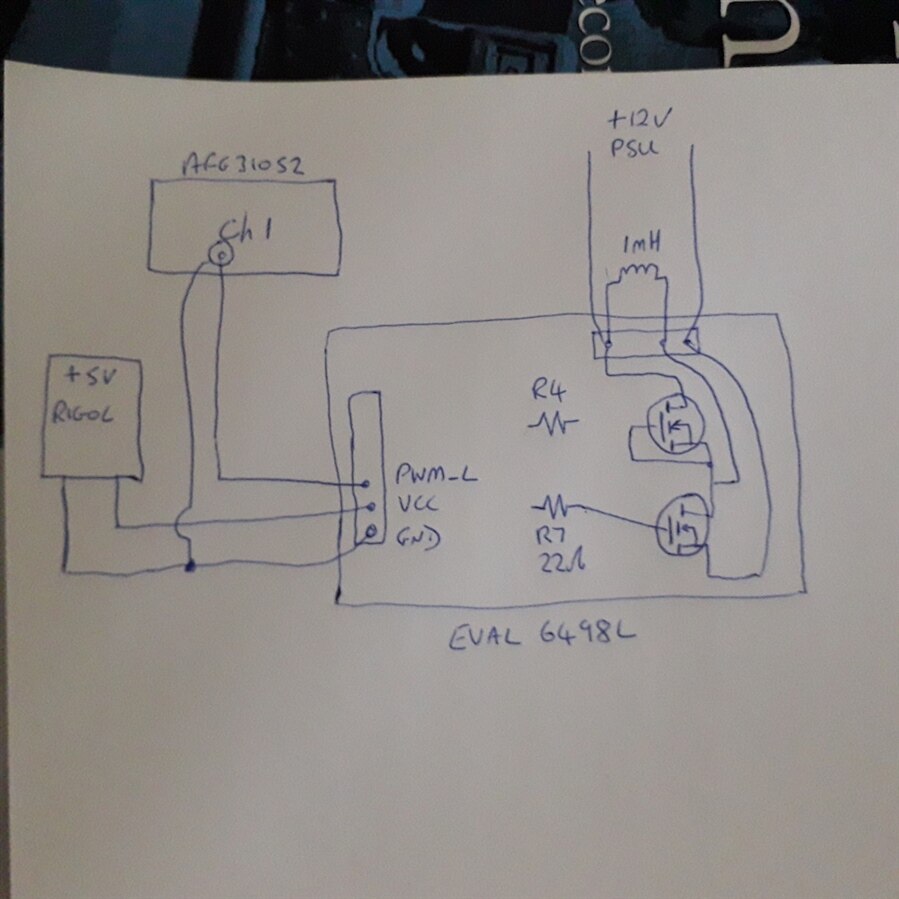
I have successfully loaded the double pulse software onto the AFG31052 and I can capture the pulse output from it on an oscilloscope. I can trace that pulse pattern onto pin 2 of the L6498L MOSFET driver. From the data sheet on the board, I believe the pulse output to the MOSFET should then come out on pin 6 of the chip onto resistor R7.
Resistor R7 I soldered in, the 320N20N MOSFET I am using suggests a value of 25 Ohms. As that seemed a little hard to find, I soldered in a 22 Ohm resistor. Initially, I also soldered in R4 to the top MOSFET, but reading the application sheet a few more times, this is not used, and I should have shorted out the gate and source of the top MOSFET. Is the upper MOSFET required at all, can I just short source to drain?
I removed R4 and shorted gate to source, but still have no pulse train to R7 and the second MOSFET.
Is this looking like I have damaged the board? I have seen that the L6498L chip can be purchased separately, but I am not sure I will be able to solder that in place on the board, so will need to get a new board, but just wanted to make sure that there isn't something else I can check before I purchase a new board.


