


Hi All,
This is my first review and I hope that my ' English translation ' is readable.
Thanks to element14 to give me the opportunity of test and review the LPCXpresso board.
The hardware out of the package
LPCXpresso join two module in a single PCB as shown in figure.
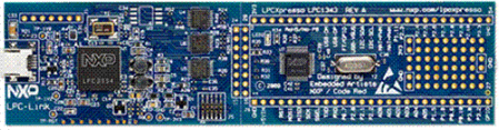
The LPC-Link on the PCB left side is the NXP USB-JTAG programming/debug tool with some interesting characteristics:
- It use a ram-based LPC3154 and load the firmware on every power-up through USB, allow easily future upgrade to support new devices, new IDE features, firmware fix-up etc.
- JTAG signal are buffered with common ICs in a easy to replace package, a little safeguard in case of target hardware accidental failure.
- JTAG interface is suitable for programming/debug a wide range of LPC MCU, need only a cheap adapter cable and can be used after cutting the connections along the J4 middle point.
The target LPC1114FBD48/301,1LPC1114FBD48/301,1 on the PCB right-side, simple but well done:
- Only the MCU, the XTAL, a LED and a few decoupler capacitors, the essential to make the MCU 'Ready to Go '
- All the MCU pin available through two 100mil spacing row allow very easy and fast interconnect with user prototype
- The good pinout compatibility with other currently available LPCXpresso board can result in a reusable prototype hardware for other target.
Set up the envinroment:
The package do not have a software CD. This solution lowering the price and also allow to start with the most recently update software package and documentation.
On the www.nxp.com/lpcxpresso webpage we can find a link to download the Code-Red IDE. Following the online detailed Getting-started guide we can perform:
- IDE installaction and activation (pag 8-10) explain how to install and license the IDE.
- Getting familiar with the LPCXpresso IDE (pag 11-14) shown basic IDE functionalityes
- Build, download and debug the blinky apps (pag 16-19) use a simple on board led-blink example to explain basic Build/debug process.
Followed the previous steps, we have now a working CORTEX-M0 board with a robust Eclipse based IDE.
Exploring code example:
The LPC11xx example directory contain 3 zip archive:
- CMSISv1p30_LPC11xx Cortex Microcontroller Software Interface Standard defines for LPC11xx device allowing reusable code template.
- 1114examples a full set of example projects, each of that focus on a specific MCU peripherals
- LPCXpresso1114 a subset of 1114examples with some common peripherals driver build into a single library
Following the example code reduce the effort to learn the on chip peripherals setting, giving us a start point to manage the device SFR.
I want to remark a very useful IDE feature. It allow to build a 'semihosting' project that intercept the write character to stdout and redirect it on the IDE console. See the LPCXpresso1114_consoleprint example for details and limitations.
Conclusion:
- a good designed hardware
- a featured IDE
- a good support
- a cheap price
Definitely, the right platform to evaluate and start to work with NXP LPC1xxx devices.
- a good designed hardware
- a featured IDE
- a good support
- a cheap price
Definitely, the right platform to evaluate and start to work with NXP LPC1xxx devices.