element14 Community
element14 Community
    Register Log In
  • Site
  • Search
  • Log In Register
  • Community Hub
    Community Hub
    • What's New on element14
    • Feedback and Support
    • Benefits of Membership
    • Personal Blogs
    • Members Area
    • Achievement Levels
  • Learn
    Learn
    • Ask an Expert
    • eBooks
    • element14 presents
    • Learning Center
    • Tech Spotlight
    • STEM Academy
    • Webinars, Training and Events
    • Learning Groups
  • Technologies
    Technologies
    • 3D Printing
    • FPGA
    • Industrial Automation
    • Internet of Things
    • Power & Energy
    • Sensors
    • Technology Groups
  • Challenges & Projects
    Challenges & Projects
    • Design Challenges
    • element14 presents Projects
    • Project14
    • Arduino Projects
    • Raspberry Pi Projects
    • Project Groups
  • Products
    Products
    • Arduino
    • Avnet & Tria Boards Community
    • Dev Tools
    • Manufacturers
    • Multicomp Pro
    • Product Groups
    • Raspberry Pi
    • RoadTests & Reviews
  • About Us
    About the element14 Community
  • Store
    Store
    • Visit Your Store
    • Choose another store...
      • Europe
      •  Austria (German)
      •  Belgium (Dutch, French)
      •  Bulgaria (Bulgarian)
      •  Czech Republic (Czech)
      •  Denmark (Danish)
      •  Estonia (Estonian)
      •  Finland (Finnish)
      •  France (French)
      •  Germany (German)
      •  Hungary (Hungarian)
      •  Ireland
      •  Israel
      •  Italy (Italian)
      •  Latvia (Latvian)
      •  
      •  Lithuania (Lithuanian)
      •  Netherlands (Dutch)
      •  Norway (Norwegian)
      •  Poland (Polish)
      •  Portugal (Portuguese)
      •  Romania (Romanian)
      •  Russia (Russian)
      •  Slovakia (Slovak)
      •  Slovenia (Slovenian)
      •  Spain (Spanish)
      •  Sweden (Swedish)
      •  Switzerland(German, French)
      •  Turkey (Turkish)
      •  United Kingdom
      • Asia Pacific
      •  Australia
      •  China
      •  Hong Kong
      •  India
      •  Japan
      •  Korea (Korean)
      •  Malaysia
      •  New Zealand
      •  Philippines
      •  Singapore
      •  Taiwan
      •  Thailand (Thai)
      •  Vietnam
      • Americas
      •  Brazil (Portuguese)
      •  Canada
      •  Mexico (Spanish)
      •  United States
      Can't find the country/region you're looking for? Visit our export site or find a local distributor.
  • Translate
  • Profile
  • Settings
RoadTests & Reviews
  • Products
  • More
RoadTests & Reviews
RoadTest Forum Seeking Your Interest In RoadTesting Ethernet or SMA Eval Kits
  • Blogs
  • Forum
  • Documents
  • RoadTests
  • Reviews
  • Polls
  • Files
  • Members
  • Sub-Groups
  • More
  • Cancel
  • New
Join RoadTests & Reviews to participate - click to join for free!
Actions
  • Share
  • More
  • Cancel
Forum Thread Details
  • State Not Answered
  • Replies 17 replies
  • Subscribers 2750 subscribers
  • Views 3315 views
  • Users 0 members are here
  • roadtester survey
Related

Seeking Your Interest In RoadTesting Ethernet or SMA Eval Kits

rscasny
rscasny over 2 years ago

Link to the second discussion. Click here

Hi All.

We've been talking with Broadcom about roadtesting one of their evaluation kits. Right now, two are being considered. I wanted to get your feedback and/or interest in roadtesting these peroducts. I also would like to know what are parts or equipment you would need to roadtest any of these products.

Let me briefly go through them. I have a poll at the bottom of this discussion.

imageEthernet Evaluation Kit

(AFBR-FSEK50B00E Gigabit Ethernet Evaluation Kit for the AFBR-FS50B00 Optical Wireless Transceiver)

The evaluation kit  for AFBR-FSEK50B00E gives the system designer a convenient means to evaluate the performance of the Optical Wireless Transceiver AFBR-FS50B00.

The evaluation kit includes:

  • Two PCBs with RJ-45 connector and IC BCM54210, which implements the functionality of a Media Converter
  • Two PCBs with Optical Wireless Transceiver AFBRFS50B00
  • One USB memory stick containing technical documentation.

The evaluation kit does not include:

  • CAT5 cables required for GbE communications between the evaluation kit and the user’s application.
  • Micro USB cables required for power supply.

Documentation

  • Datasheet

For More Information

SMA Evaluation Kit

imageBROADCOM AFBR-FSEK50B00S SMA Evaluation Kit, AFBR-FS50B00, Optical Wireless Transceiver, Wireless Communication
SMA Evaluation Kit for the AFBR-FS50B00 - 5 Gb/s

The Broadcom® AFBR-FSEK50B00S is an evaluation platform for the Optical Wireless Transceiver AFBR-FS50B00. The AFBR-FSEK50B00S evaluation kit provides the system designer a convenient means to evaluate the performance of the AFBR-FS50B00 optical wireless transceiver.

The evaluation kit includes:

  • Two PCBs with SMA connectors and AFBR-FS50B00 optical wireless transceiver
  • Two jumpers

The evaluation kit does not include:

  • Coaxial cables required for communication through the AFBR-FS50B00 optical wireless transceiver
  • Cables required to supply power to the boards included in the evaluation kit

Documentation

  • Datasheet

For More Information


About the Broadcom® AFBR-FS50B00 Transceiver

The Broadcom® AFBR-FS50B00 is a transceiver that communicates data over free space and thereby allows connector-less/cable-less
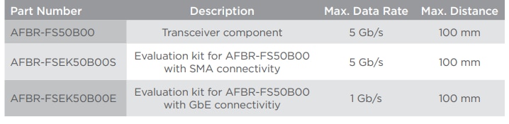
communication in a variety of applications. Full-duplex bidirectional communication, together with a small form factor, allows a compact system design. The device keeps full functionality over a 360° rotation around the optical axis, which reduces the complexity of alignment on the system level and allows the use in rotating systems. The component is designed to operate over a wide temperature range and with a potential data rate up to 5 Gb/s and a variable distance from 20 mm up to 100 mm. The AFBR-FS50B00, a Laser Class 1 product, is RoHS-compliant and is designed for SMT solderability standard processes
image

RoadTester Poll


  • Sign in to reply
  • Cancel
  • rscasny
    0 rscasny over 1 year ago

    Thanks for the comments.

    • Cancel
    • Vote Up 0 Vote Down
    • Sign in to reply
    • Verify Answer
    • Cancel
  • JWx
    0 JWx over 2 years ago in reply to dougw

    or maybe CWDM? CWDM technology have gotten way cheaper recently...

    • Cancel
    • Vote Up 0 Vote Down
    • Sign in to reply
    • Verify Answer
    • Cancel
  • dougw
    0 dougw over 2 years ago in reply to saadtiwana_int

    The slip ring application is very interesting.

    Although you could have multiple fiber links in fairly close proximity, you could only have one fiber in a slip ring application because a slip ring must rotate around a single free-space optical link. You could, of course, use OFDM to send multiple channels though a single link. I'm a little bit tempted to try this technology in a slip ring application.

    • Cancel
    • Vote Up 0 Vote Down
    • Sign in to reply
    • Verify Answer
    • Cancel
  • rscasny
    0 rscasny over 2 years ago in reply to saadtiwana_int

    You ask some detailed, specific questions that I'm not sure the datasheet alone would answer them. I can ask Broadcom.

    Randall

    • Cancel
    • Vote Up +2 Vote Down
    • Sign in to reply
    • Verify Answer
    • Cancel
  • saadtiwana_int
    0 saadtiwana_int over 2 years ago

    This is a very interesting device and I never knew this existed (up to 5Gbps!). The reason I find it interesting is because I see it as the easiest way to implement an optical slip-ring. At work, we use some very complicated  (and expensive) optical slip rings to pass fiber links across rotating things. Something like this could simplify that task by at least two orders of magnitude. The SMA version of the kit is more interesting because The TX/RX can be directly connected to any FPGA Eval kit with transceivers to test. Those typically come with SMA TX/RX ports too so it should be fairly straight forward to test. BERT tests can also be done this way.

    The thing I don't like too much is that there isn't much information about the device itself (detailed datasheet?) on the Broadcom website, and also pricing is not available anywhere. For example, I wanted to understand if multiple of these can be used in the vicinity, and how accurate the optical alignment needs to be, etc. This information would dictate what specific use cases it could be used in, for example building slip rings with multiple fibers, etc.

    • Cancel
    • Vote Up +2 Vote Down
    • Sign in to reply
    • Verify Answer
    • Cancel
  • DAB
    0 DAB over 2 years ago

    I have interest, but not the equipment to do an adequate test.

    • Cancel
    • Vote Up 0 Vote Down
    • Sign in to reply
    • Verify Answer
    • Cancel
  • shabaz
    0 shabaz over 2 years ago in reply to kmikemoo

    I've had that same experience.. trying a high-value attenuation and getting nowhere near it! 

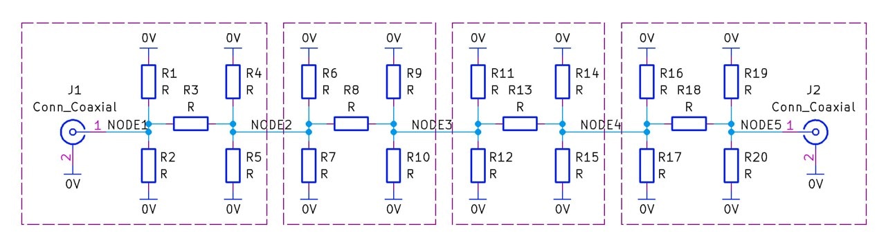
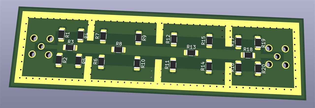
    I was wondering how to seal each stage, in the easiest-to-assemble way I could think of. I sketched the following, it still needs work, and might not be the best way.

    If (say) it was a 4-stage (where each stage shouldn't be more than about 25 dB) then that's 100dB of attenuation if desired.

    image

    The idea being that each section could be boxed with a screening can. The resistors (or at least some of them) would be large (e.g. 1210 sized) SMD, so that they could dissipate some power.

    image

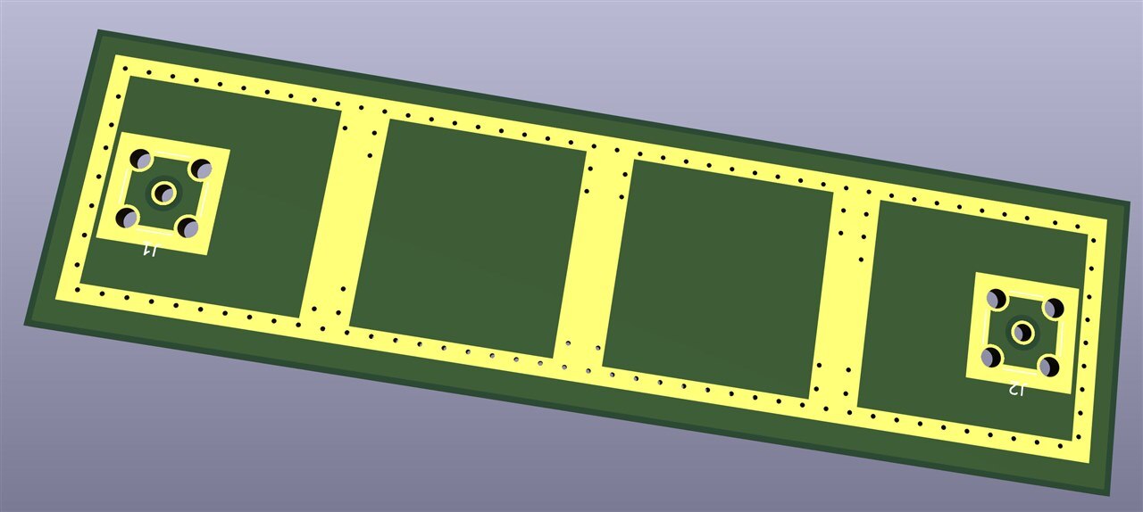
    Once the cans are soldered (with a high-power iron), the adjacent cans joining each stage would need to be bridged with solder too, to prevent RF finding a way to the outside world between the stages.

    The cans are cheap in quantities of 10. Slightly taller versions would be better, but this is all I could find and might be OK:

    image

    The SMA connectors could be soldered on the other side, and then solder used to fillet all the way around the edges of each connector. Also every via hole could be soldered over if required!

    image

    Don't know if it's worth building though, because it would be hard work to solder the cans without a high-power iron. Also it would only work up to a few hundred MHz.

    Regarding a coupling loop near an attenuator (if it isn't fully shielded), or close to coax braid, it would work, but would be hard to know what the attenuation would be (and it might vary over frequency). But might be good enough! 

    • Cancel
    • Vote Up +1 Vote Down
    • Sign in to reply
    • Verify Answer
    • Cancel
  • vishwasn
    0 vishwasn over 2 years ago

    Interesting device. I'm thinking of applications in network switches where it can avoid some links between stacked PCBs but there are challenges such as the presence of dust and dirt particles on the optical sensor causing noisy data transfer. Still, I would like to test this as we have some good test equipment for this at the University of Colorado Boulder. High-Speed Digital Engineering department. 

    • Cancel
    • Vote Up 0 Vote Down
    • Sign in to reply
    • Verify Answer
    • Cancel
  • kmikemoo
    0 kmikemoo over 2 years ago in reply to shabaz

    Hi shabaz .  The box is just a lazy man's way of terminating a SO-239 connector.  The bolt on the side is because I gave up trying to land the shield on the aluminum.  It's just a ring ternimal, bolt and nut.  I bought a number of the bodies thinking to build attenuators but they turned out rather poor.  Right now, I only use attenuators for radio direction finding - so I purchased a few and made one out of strip board that attenuates 46dB.  The calculator says 116dB but the coupling says... "I don't think so." Laughing

    I've been experimenting on and off with trying to attenuate 500mW to 750mW signals.  I have intentionally bought and made inefficient antennas.  You would be surprised how effective a 3-stack of 30dB attenuators works as an antenna.  Wouldn't a coupling loop near the dummy load act like a potential transformer?  It would be hard to get accurate level readings without plotting a bunch of known values.  I may have to try that out.

    • Cancel
    • Vote Up 0 Vote Down
    • Sign in to reply
    • Verify Answer
    • Cancel
  • shabaz
    0 shabaz over 2 years ago in reply to kmikemoo

    Hi Mike, 

    Interesting! Glad you're finding what works. Also, just curious, is the box an attenuator?

    image

    Depends how it's built of course, if it's super-high attenuation in there (e.g. 30dB or more) the RF might be coupling unexpectedly despite the attenuation.

    I found that out when trying to attenuate by 100dB or something (I wanted to do a similar thing, feed a transmitter into a radio receiver), and ended up using separate 20dB and 10dB attenuators (each with their individual metal cylinders) all chained up, and it was totally impractical admittedly! Partitioning inside the enclosure (e.g. walls of copper-clad PCB) could be another idea.

    Recently I found this nice thing on eBay (but it's not high power, so would still need a higher-power attenuator to front it):

    image

    I've not tried it out yet! Hoping it works. 

    EDIT: This would be another way to do it; using a coupler to get less of the signal (and pass the rest into a large dummy load), but this one only offers 15dB reduction, and only supports 4W. Maybe there are higher-power DIY versions suitable for HF use, but I've never checked to see.

    image

    • Cancel
    • Vote Up 0 Vote Down
    • Sign in to reply
    • Verify Answer
    • Cancel
>
element14 Community

element14 is the first online community specifically for engineers. Connect with your peers and get expert answers to your questions.

  • Members
  • Learn
  • Technologies
  • Challenges & Projects
  • Products
  • Store
  • About Us
  • Feedback & Support
  • FAQs
  • Terms of Use
  • Privacy Policy
  • Legal and Copyright Notices
  • Sitemap
  • Cookies

An Avnet Company © 2026 Premier Farnell Limited. All Rights Reserved.

Premier Farnell Ltd, registered in England and Wales (no 00876412), registered office: Farnell House, Forge Lane, Leeds LS12 2NE.

Follow element14

  • X
  • Facebook
  • linkedin
  • YouTube