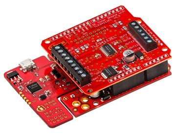
Infineon DC Motor Shield w/ TLE94112EL for Arduino

View table of contents ...  

image


{tabbedtable} Tab LabelTab Content
About

The Infineon DC motor shield is a small evaluation board equipped with  TLE94112EL for use with Arduino. The TLE94112EL is capable to drive up to 6 small DC motors in parallel mode or up to 11 DC motors in cascaded mode. All outputs can drive up to 0.9A. The outputs can be used stand-alone or combined to increase driving capability up to 3.6A.


image

Infineon DC Motor Shield with XMC1100 Boot Kit for Arduino


Features:

Driver with 12 half-bridge outputs to drive DC motors, resistive or inductive loads

  • Driver is protected against over-temperature, over-current, over-voltage, under-voltage and enables diagnosis of over-current, over-voltage, under-voltage
  • SPI interface with zero clock diagnosis
  • Enhanced EMC performance
  • Integrated PWM generator with 3 different frequencies (80Hz, 100Hz, 200Hz)


Benefits:

  • Shield enables compact design for multi-motor applications
  • Cost efficient design for multi-motor applications
  • Less communication with µC through integrated PWM generator and zero clock diagnosis
  • Lower cost by reducing external components to EME requirements


Applications:

  • Multi-motor applications
  • DC motors and voltage controlled bipolar stepper motors
  • Toys
  • HVAC systems


Click here to obtain XMC1100 Software for Arduino IDE

Important Dates

Enrollment Begins: Mar 12 2017

Enrollment Ends: Apr 18, 2017

RoadTesters Selected: Apr 25 2017 (estimated)

Product Shipped: May 19 2017

RoadTesting Begins: May 26 2017

Reminder/Update Email: July 10 2017*

Submit Reviews By: July 30 2017**


*The element14 RoadTest Staff will send this reminder/update email.

**If a RoadTester is unable to meet the deadline, please notify the RoadTest Program Lead, , as soon as possible before the deadline.

RoadTesters

The supplier selected the following applicants as official RoadTesters:


Terms & Conditions

DC Motor Shield with TLE94112EL for Arduino – RoadTest

Terms and Conditions

These are the terms and conditions which govern the DC Motor Shield with TLE94112EL for Arduino RoadTest contest. This Contest requires participants to submit an application indicating their previous experience with this type of equipment/component, information on what they would do to test the equipment/component, and the applicant’s desire to post a thorough review of their experience with images, photos, or other supplemental materials. Participants will be required to meet the Conditions for Participation.  The winners of this RoadTest will receive the item(s) listed below. RoadTest Reviews are due no later than 60 days after the receipt of the item(s). No other prizes are offered.

The Principal terms of the Competition:

The following words and phrases are used in these terms and conditions and have the meanings given to them below.

RoadTest: DC Motor Shield with TLE94112EL for Arduino

(RoadTest or Contest)

Key dates:

Applications Close: midnight (GMT) on 17 March 2017

Announcement of Winner (estimated): 24 Mar 2017


Prize:  DC Motor Shield with TLE94112EL for Arduino

Additional Prizes: none

Competition Site: https://www.element14.com/community/groups/roadtest?ICID=menubar_resources_roadtest

Site or element14 Community: www.element14.com/community

Judges: members of the element14 community team chosen at the Organiser’s discretion.

Judging Criteria, All of the following which will have equal weighting:

· Demonstrated competence with the technologies including links or descriptions of past projects

· Qualifications as indicated by current job role and/or schooling/vocational training;

· A thorough description of how the prize would be tested;

· Likelihood that the Applicant will blog about the prize and provide a review on element14.com;

· Originality;

· Innovation.

Organiser: Premier Farnell plc (registered in England and Wales under company number 876412) whose registered office is at Farnell House, Forge Lane, Leeds, UK

Conditions for Qualification: in addition to meeting the requirements of these terms, all persons applying to take part in the Contest (each one an Applicant) must:

· Provide a RoadTest application describing what he/she would do if awarded the Prize including similar previous projects, product experience and qualifications

Terms: these terms and conditions which govern the Competition and to which the Organiser reserves the right to make changes from time to time and the latest version of these Terms from time to time will be posted to the Site.

  1. Eligibility
  2. Applications:
  3. Selecting Winners:   
  4. Liability:
  5. General:

1.1 Save as set out in these Terms, the Contest is open to any natural or legal person, firm or company or group of natural persons or unincorporated body.

1.2 All Applicants must be aged at least 18 at the time of their application.

1.3 Applicants must not enter the RoadTest if doing so or taking part may:

1.3.1 cause the Organiser and/or themselves to be in breach of any agreement (including but not limited to any contract of employment) to which they are a party or in breach of any law, regulation or rule having the force of law to which the Organiser or the Applicant may be subject or any policy of the Organiser or the Sponsor;

1.3.2 Require the Organiser to obtain any licence, authorisation or permission to deal with the Applicant; or

1.3.3 Be in breach of any policy or practice of their employer. Some employers prohibit or restrict their employees from taking part in competitions such as these or receiving prizes under them and the Organiser respects those policies and practices.

The Organiser reserves the right to disqualify any Application made in breach of these Terms and to reject any Application which it reasonably believes may be or become in breach. The Organiser reserves the right to require evidence in such form as the Organiser may reasonably require of any Applicant’s compliance with any of these Terms and to disqualify any Applicant or Participant who cannot provide such evidence reasonably promptly. 

1.4 Multiple applications are not permitted.

1.5 Applications may not be submitted by an agent whether acting on behalf of an undisclosed principal or otherwise.

1.6 The Contest is NOT open to:

1.6.1 Any person or entity who is a resident or national of any country which is subject to sanctions, embargoes or national trade restrictions of the United States of America, the European Union or the United Kingdom;

1.6.2 Any employee, director, member, shareholder (as appropriate) or any of their direct families (parents, siblings, spouse, partner, children) (“Direct Families”) of the Organiser and Sponsors; or

2.1 Each Applicant must fully complete and submit a RoadTest Application by the Application Close.

2.2 By submitting a Registration Form, each Applicant:

2.2.1 Authorises the Organiser to use his or her personal data (as defined in the Data Protection Act 1998) for the purposes of running and promoting the RoadTest;

2.2.2 Authorises the Organizer to copy, reproduce and publish their application should they be accepted as a Participant;

2.2.3 Will be deemed to have read, accepted and agree to be bound by these Terms. Applicants are advised to print and keep safe these Terms;

2.2.4 Authorises the Organiser to copy, reproduce and use the Application and/or Review for the purposes of the RoadTest and as otherwise contemplated by these Terms. The Organiser will not be responsible for any inaccuracy, error or omission contained in any reproduction or use of the Project Blogs.

2.2.5 Licenses the Organiser to use the intellectual property in the Project (IP) for the purposes of this Contest. As between the Applicant and the Organiser the IP remains owned by the Applicant.

2.2.6 Grants the Organiser the right to use his or her likeness, photographs, logos, trademarks, audio or video recordings without restriction for the purposes of Contest or the promotion of it or the Site;

2.2.7 Agrees to participate positively in all publicity surrounding the Contest;

2.2.8 Agrees to be responsible for all expenses and costs incurred by him or her in preparing for, entering and participating in the Contest (save for any expenses expressly agreed by the Organiser to be borne by it in these Terms);

2.2.9 Confirms that he or she owns all IP used in his or her application or Project or Blogs and indemnifies the Organiser from any claim by a third party that use of any material provided by an Applicant to the Organiser infringes the intellectual property rights of any third party;

2.2.10 Agrees not to act in any way or fail to act in any way or be associated with any cause or group which would have a negative impact on the reputation of the Organiser and/or the RoadTest.

2.3 All applications submitted to this RoadTest must meet the following criteria:

2.3.1 Applicants must be the author, creator and owner of the proposed review idea. Applicants must not submit someone else’s idea;

2.3.2 The proposed application must be reasonably achievable by the within the time constraints of the Contest; 

2.3.3 Applications must not include or propose any of the following, the inclusion of which shall render any proposed application ineligible:

(a) Applications which relate to socially taboo topics, such as illicit drug use or sexual gratification;

(b) Applications that are or could reasonably be considered to be illegal, immoral, discriminatory or offensive as determined by the Organiser;

(c) Applications in relation to them which if accepted would infringe or breach any of the policies or terms of access or use of the Site.

2.4 No Application may contain any of the hazardous substances identified by Article 4 of Directive 2002/95/EC of the European Parliament on the Restrictions on the Use of Substances in Electronic and Electrical Equipment ("the Directive") or the use of such hazardous substances in the in any such Project must not exceed the maximum concentration values set out in the Directive.

3.1 Winners will be selected by the Organiser on the basis of the quality of his or her application and its adherence to these Terms.

3.2 The total number of Winners selected will be at least the minimum number set out above but the actual number is at the sole discretion of the Organizer and/or the Sponsor, if applicable.

3.3 The Organiser will use all reasonable efforts to announce the Winners via an update to the RoadTest page by the date listed above.

3.4 Winners agree to take part in all publicity which the Organiser or the Sponsor wishes to use to promote the RoadTest, the Products featured or other Contests with which the Organiser may be connected from time to time.

3.5 Details of the Winners may also be published in the media.

3.6 Winners are responsible for all applicable taxes, duties or other charges payable in relation to any prize.

3.7 

4.1 The Organiser hereby excludes all and any Liability arising out of the Contest or the acceptance, use, quality, condition, suitability or performance of any Prize, even where that Liability may arise from the Organiser’s negligence.

4.2 Nothing in these Terms will affect any Liability of the Organiser for death or personal injury arising from its negligence, for breach of Part II of the Consumer Protection Act 1987 (in the event that any entrant is entitled to claim rights under the Consumer Protection Act 1987) or for any matter in relation to which it would be illegal for the Organiser to exclude or to attempt to exclude its Liability.

4.3 Subject to 4.2, neither the Organiser, any parent company nor any subsidiary of the Organiser or such parent company or any of their directors, officers and employees (together referred to in these terms and the ‘Associates’) makes any guarantee, warranty or representation of any kind, express or implied, with respect to this Competition or the Prizes potentially available under it. Neither the Organiser nor any of its Associates shall be responsible for any Liability that may arise out of or in connection with person’s participation in this Competition, the claiming, redemption or value of any prizes under it, the use or enjoyment of such prizes or any events or circumstances arising out of or in connection with any of them. Any implied warranties of condition, merchantability or suitability or fitness for purpose of any of them are hereby expressly excluded. Wherever used in these Terms, ‘Liability’ shall mean any and all costs, expenses, claims, damages, actions, proceedings, demands, losses and other liabilities (including legal fees and costs on a full indemnity basis) arising directly or indirectly out of or in connection with the matter concerned. 

5.1 The RoadTest is organised and sponsored by the Organiser. The Organiser reserves the right to delegate all or any of its powers, rights and obligations arising in relation to the RoadTest to any Associate and certain such rights and powers are assumed by the Organiser on behalf of itself and each Associate. Reference to “Organiser” shall be deemed to include reference to each Associate.

5.2 The RoadTest may be terminated at any time if there are, in the sole opinion of the Organiser, an insufficient number of entries, or if the Applications are not of an appropriate standard for a competition of this nature. The Organiser has the right to cancel or suspend the RoadTest at any time due to circumstances outside its reasonable control.

5.3 The Organiser shall have the sole discretion to disqualify (without correspondence or right of appeal) any Applicant it considers to be adversely affecting the process or the operation of the RoadTest or to be in breach of these Terms or to be acting in a disruptive manner or with intent to annoy, abuse, threaten or harass any other Applicant or Participant.

5.4 The Organiser has the right to amend or add to these Terms from time to time. Revised Terms and Conditions will be posted on the Contest Site and it is a condition of entry to the RoadTest that Applicants agree to comply with these Terms and, if appropriate, such Terms as amended from time to time.

5.5 Headings are for convenience only and do not affect the interpretation or construction of these Terms and Conditions.

5.6 These Terms and the operation of the Contest shall be governed by and construed in accordance with English Law and any claim or matter arising under these Terms shall be subject to the exclusive jurisdiction of the English courts.

RoadTest Reviews
Comments
Anonymous
  • Hi Tom,

    all your issues sound a little strange to me. I triggered a shipment of another shield for you. It will come via Randall. The battery you mentioned should work. Since it is strong enough to deliver the starting current for the motor. Also for light bulbs you can run in problem with the power supply. When you switch on a light bulb you will get the so called inrush current (filament is still cold). This is a high current which will flow for ms until the bulb reaches its normal operating temperature.

    The TLE94112 is not in my direct product responsibility , but I had this issue with a 12 V car bulb and a 5 A power supply.  12Vx5A = 60W. I couldn't switch on the bulb (50W) because the power supply switched off because it was not able to deliver this inrush current. But later on you mention that your supply can drive the motor stand alone without the Shield switching it. This means that the supply can drive the motor. Alternating current electric motors may draw several times their normal full-load current when first energized.  The same with the inrush current for the light bulb (5 to 8 times higher than the nominal current).

    What I thought was that the inrush current drops down your supply and it will switch off or similar.. This seems to be not the case. But the voltage will drop for a short period of time which will make the multi half bridge to detect an under voltage and switch off.  Could you read out the status register SYS_DIAG_2 to SYS_DIAG_7 (see the sketch) for 5, 6, and 12V supply voltage?


    Best Regards

    Johannes


  • Hi Mark,

    yes this is the mentioned sketch. I managed to post it.


    Best Regards


    Johannes

  • Manuel I posted one on github as well last night, see the earlier comment.  Thanks much!  Thanks too Mark!


    I got the TLE94112EL_TestSketch file too Mark.  Thanks!~

  • Unfortunately, I got no sketch from Johannes, so I can't send you anything right now.

    Not sure if this is the same sketch, but he managed to post one here.


    TLE94112EL_Test_Sketch.zip


    Excellent support ... well done guys.

    Mark

  • Dear Tom,


    I approved you as a follower, now we should be able to exchange messages.

    Unfortunately, I got no sketch from Johannes, so I can't send you anything right now.


    Just a side question (could have overread it), did you also test the library for the shield?
    There is a sketch which was tested with a scope by an engineer here at Infineon and should also produce output which we can use for debugging.


    https://github.com/Infineon/DC-Motor-Control-TLE94112EL/tree/master/examples/pwm_demo


    You could run this sketch with a minimum setup (only a power supply) and we compare it directly with a board here using a similar setup.
    Or you modify this sketch and send it to us so that we reproduce the test. If there are differences, we could directly see it and compare it.

    Just a suggestion from my side.


    I see from your other post that you haven't lost your sense of humor, that's good to see!
    Was laughing a lot while reading it image


    Thank you for your wishes and best regards,


    Manuel

  • Manuel and Johannes,

    I have written a sketch for testing my shield as per Johannes' instructions above.  I will run the test tomorrow as it is getting late now.  I will use different motors, power supplies, etc. and will document data, Serial Print screen captures etc. and list them here.  Excuse my lack of looping to make the sketch shorter but it is getting late and my brain is short-circuiting....lol...for now you can find it here if you want to take a look at it:  https://github.com/gl1der1/Infineon-Motor-Shield-RoadTest


    Thanks and Happy Holiday!

    Tom

  • Hi Gerald!


    Thanks!  It has a similar appearance to the brushless motors we often use for electric remote control airplanes.  Since the cooling fan is brushless and it seems to work fine with the motor shield, I was asking because I am thinking about a possible application for remote control vehicles that use brushless motors.  As soon as I can ascertain a good working Shield, I think I will test it as well on these brushless motors to see how it behaves.  Thanks for the info and the great images!


    Tom

  • Hi

    Gerald, it would appear in your above post that at least one of your motors (the 12V Xinrulilian cooling fan) is a BRUSHLESS motor fan (I'm not sure about the other motor in the vise, but based on my experience with the Remote Control Electrical Airplane hobby), that motor appears to be BRUSHLESS also.  However, Infineon's User Manual for the DC Motor Control Shield with TLE94112EL for Arduino, Page 4, Section 1.2 Key Features  says "The DC Motor Control Shield has the following features:....... BRUSHED DC Motor Control up to .9A peak".....I made sure my test motors are BRUSHED----does using BRUSHLESS motors make a difference?


    The first motor i use is a permanent magnetic DC motor. -> also, brushed DC motor.

    imageimage

    In the application i use this motor as servo for moving mechanics.


    Best Regards,

    Gerald

    ---

  • I forgot Manuel and Johannes---you'll have to approve me as a "follower" before I can send you a direct message.


  •  

    Dear Manuel and Johannes:

    1.  Don't I feel like and idiot?...lol...I didn't realize that Johannes was from Infineon also.......lol.....

    2.  If that sketch is for me, you can email it directly to me.  I will send you and Johannes my direct e-mail if that will be easier.

    3.  Please, don't apologize for the Public Holiday!!!  (I used to work for our Federal Government in the US---do you know how many Public Holidays we have a year?......lol...)

    4.  However, you can apologize for being German!  (lol....that was a joke I am kidding---I am German by descent, my mother and father's family were Maas' and Aldrich's----sound German?)....lol

    5.  I will do my best to stick with this, as I am now retired and love working with electronics and such.  My primary frustration has been in determining whether this has been my fault, but I have explored all possibilities that I can think of, and I think the board/chip just may be defective.
    6.  Finally, thanks again for your reply and your support.  I will look forward to running your new sketch (check your messages for my email)!


    Thanks,

    Tom

  • Dear Tom,


    Sorry for my delayed response.
    Johannes is also from Infineon and please regard his help as coming from the same source, I am in close contact with him.
    He is also taking care of support for this roadtest and he is in charge of the contact to element14.

    Therefore, you already have the right person here who is helping you to figure out the problems, even if I am not directly replying, my colleagues are having an eye on it.


    @Johannes: Feel free to send me the sketch, I can put it on our GitHub account and we share it here


    My personal feeling is that we are somehow stuck in a cycle where almost everything has been tried out and still the problems remain.
    Let's try the sketch as soon as I have uploaded it or Johannes send it if this helps to get more insights.
    As Johannes said, sending a new board should not be the problem, we need to figure out the timeline and how easy and fast it can be done image


    Unfortunately, here in Germany we have a public holiday tomorrow and many will be off taking an extended weekend, so I expect no result before Monday.

    But I am working on it and already pinged my colleagues, waiting for response to update you.


    Sorry for the inconvenience and thank you very much for your effort.
    You are not giving up which is, from my point of view, amazing as you are really putting lot's of effort into it.


    Best regards,


    Manuel

  • Thanks Mark, excellent Idea.


    So I replaced Motor 1 (Outputs 1 & 2) with a 7.5v -.220 A rated light bulb.  Nothing.  Same results.  Filament did absolutely nothing, error codes abounded that really made no sense.  I've run the motors with direct supply source (no shield) before with my multi-meter connected in line and set to maximum as I mentioned above and I have never captured a reading as high as the .9 A limit.  highest has been around .7 A.


    I'm reasonably sure that:

    1.  I'm jinxed; or

    2.  Quality control is not good on these card;

    3.  They were mishandled before or during shipment that caused damage.


    Thanks much!

  • Hi Johannes thanks again for the reply.


    I was working late last night (unfortunately I didn't record anything) using the Oscilloscope, multi-meters, Diagnostic Registers, etc.   Nothing Different.  Remember I have used not only the 6 motors you see in the video but I have various other motors from 3 to 15 volts and they all do the same thing.  Also, I use them with more that just the power supply you see in the video, including a 12v Sealed Lead Acid Battery with a rating of 5Ah (Not a car battery but it does well enough to simulate one for this test.)  These motors are small 6V motors and I have run them from a supply source that can only produce .5A so they can't be overloading the Shield,, and my my meters and scopes basically confirm that.  Remember, regardless of the motor, regardless of the supply type, the only operating voltage range I can use with the shield (and then the results are NOT reliable) is between 5.1 and 6.1V.


    Yes, I get all kinds of error messages, but nothing that really makes much sense.  I will just continue to test the Shield the best I can and report the (unfortunately negative) results in my report, unless Randall or Manuel or someone can provide me with another card.  I thought it was odd that both the shield and the XMC1100 card would not work correctly, but after getting the replacement XMC1100 card and it working fine, I'm beginning to wonder once again if it is more than just "coincidental" that both the card and the shield that were in that same shipment appear defective.  Perhaps the package was treated roughly or was exposed to some sort of radiation (any major solar flares lately?....ha..ha...)  It also seem strange that the shield, though packages in an "anti-static" plastic bag, was loose in the bag, the bag unsealed (with a previously attached seal that was broken).  Oh well,  like I said, I'll keep trying.


    Anyway, perhaps one of the more knowledgeable members or employees of Element14 have a better answer than the following for you for your question about posting a sketch, but the easiest way I know how you can do it is to put the sketch file on GitHub https://github.com/ first.  Then, when writing your comment click the link button (about the 9th button from the left above) and post the link to the Github repository where anyone can download it.


    Cheers!


    Tom

  • Hi Thomas,

    at 5.0V and 5.5V you see

         - a Load Error   (presumably overcurrent, but the status diagnose has to be read back ) and the outputs are switched off (latch off)

         - and a VS undervoltage


    at 6V you only see
         - a Load Error. this means the voltage doesn't break down deep enough for a VS under voltage error.  The
    Load error stays.


    I would like to post a sketch (zip) How does this work?


    This sketch activates the motors connected between OUT1-2 and OUT3-4.


    One cycle:

    • Activation for 2 s in one direction
    • The motors are braked for  300ms
    • Activation for 2 s in the other direction
    • The motors are braked for  300ms


    The open load and overcurrent for OUT1-4 registers are read back during
    each activation/deactivation.

    The overcurrent and open load registers for OUT1-4 are cleared at the
    end of each cycle.


    It would be interesting to have the data sent by the serial monitor for
    5, 6V and 12V supply.

    I also suggest to increase the current limitation of the power supply to
    e.g. 2A.


    As discussed I suspect that:

    • some motors draw too much current and trigger the
      overcurrent latch-off
    • At low voltage,  power supply output drops below
      the device undervoltage shutdown (due to the motor inrush current)


    BR

    Johannes

  • Thomas

    I'm curious about your power supply.

    The terminal suggests 1A, so is there some current limiting device inside?


    The voltage meter certainly remains at whatever you set, but that may also be a function of the meter.


    FYI

    A motor that is rated at 0.7A running is likely to draw 4-6 times that current during startup

    These are relatively crude motors, and have excellent torque but at the expense of current.


    The spec sheets makes one small but important distinction

    The main application targeted by the TLE94112EL is brushed DC motor control with peak currents below 0.9A.


    The stall current of 1.x amps suggests the motor may draw much more than the 0.9A peak.

    Reducing the voltage will possibly make ot come down, but I suspect not enough.


    Cheers

    Mark

  • Thomas

    What happens if you substitue the motor for a resistor or light bulb.


    it might help remove the inductive aspect and see if the problem is the load.


    Mark

  • Thanks Johannes.  Although I haven't had time to implement the tests you have suggested due to personal obligations, I intend to very shortly.  However, in the interim, I have a created a video of my current set-up for testing the Infineon Sample Sketch that I keep referencing, demonstrating the odd, erratic behavior I am getting at the unusual voltages (such as what appears to be the "best" behavior/reaction of the motors/shield to a supply voltage below the specified 5.5V lower limit).  I have dubbed narration for the sake of explanation; the video was a quick "put together" so excuse any mistakes please.  Also, in addition to this video, I have screen captures of a few Serial Monitor prints for different photos I will add to this or immediately following.  All tests (different voltages) were conducted by first turning on the USB cable to the Arduino, allowing a few seconds for the Arduino to boot up, then turning on the power supply and the voltages seen in the video.  After each run, the power was shut off and the USB was disconnected for at least a minute to allow plenty of time for everything to "Clear and reset."  I have other Sketches that I have written myself to test just single motor operation and other conditions but I have not included any of those.  The video can be viewed here or on Youtube at

    https://youtu.be/E621GOe_LHM


    5.1V Serial Print Out of SDI: and SDO;'s (See the remarks in Infineon's sample sketch for Arduino for further explanation).  Each Serial Monitor recording was initiated right after start up for that voltage setting.

    image

    5.5V Serial Print Out

    image

    6V Serial Print Out

    image

  • Hi Thomas,


    “According to the
    schematic and the illustrations in that manual, it appears to me that that is
    what C1-C4 are present on the shield for (improved EMC performance). “


    C1 to C4 are required for brush DC motors and brushless DC motors. The
    placement of these capacitors (especially C1-C3) are crucial for the high
    frequency noise (emitted by the VS pins)

    I would like to stress that the EMC aspect is important for commercial
    modules. Don't worry about the EMC topic, besides you want to go and sell your circuitry and design to e.g. a car company. It is important for EMC but not for the functionality.


    The TLE94112 could also drive BLDC motors or even stepper motors (in
    voltage mode), but the PWM frequency is limited to some hundreds of Hz.

    This limitation comes from the fact that the turn-on / turn-off slopes
    have been optimized for low emission at the outputs.  Besides it its way more complicated from the software side to drive a BLDC motor.


    Best Regards


    Johannes


  • I'm confused, and I do apologize to all if it is do to my lack of Electrical Engineering knowledge (I'm a longtime hobbyist, not an Electrical Engineer).  However I do have some questions (I am not criticizing anyone at all so please do not misunderstand my questions; I am genuinely seeking knowledge).


    Gerald, it would appear in your above post that at least one of your motors (the 12V Xinrulilian cooling fan) is a BRUSHLESS motor fan (I'm not sure about the other motor in the vise, but based on my experience with the Remote Control Electrical Airplane hobby), that motor appears to be BRUSHLESS also.  However, Infineon's User Manual for the DC Motor Control Shield with TLE94112EL for Arduino, Page 4, Section 1.2 Key Features  says "The DC Motor Control Shield has the following features:....... BRUSHED DC Motor Control up to .9A peak".....I made sure my test motors are BRUSHED----does using BRUSHLESS motors make a difference?


    Also, the referenced Motor Shield PDF says under "Scope and purpose" that "It should be used in conjunction with the TLE94112EL Datasheet."  The TLE94112EL Datahseet pdf, Page 23, Section 5 General Description, Subsection 5.1 Power Supply says in the last paragraph, "An electrolytic and 100nF ceramic capacitors are recommended to be placed as close as possible to the Vs supply pin of the device for improved EMC performance in the high and low frequency band.  The electrolytic capacitor must be dimensioned to prevent the VS voltage from exceeding the absolute maximum rating.  In addition, decoupling capacitors are recommended on the Vdd supply pin."  Referencing back to the Motor Shield User Manual, Section 2.4 Bill of Material of the DC Motor Shield Lists C1, C2, C3 Kemet 100n/50v cpacitors and C4 a Panasonic 47uF/50Capacitor (eletrcolytic).  According to the schematic and the illustrations in that manual, it appears to me that that is what C1-C4 are present on the shield for (improved EMC performance).  In addition, Figure 14 Motor Control Shield connectors shows how the motors should be connected to the shield outputs for use with the example Arduino sketch.  Although this is not exactly a "Schematic" it does NOT show any additional capacitors connected to the Motors for the purpose of EMC filtration.  Finally, the shield manual says on page 13, Section 3.1 Key Features of the TLE94112EL "Optimized EMC behavior". 


    To summarize, because of those refernces I am NOT using BRUSHLESS motors or any additional capacitors for EMC filtration which appears to be the case in your video/photograph above.  Does this make a difference?   Should I be using the capacitors or BRUSHLESS  motors instead?

  • Hi

    ....

    6. I have placed multiple Multimeters while attempting to run the motors to monitor Amperage and Voltage. I have tried using the "Maximum" setting on the multimeters monitoring Amperage and no single motor has ever gone over 0.700 Amps (this includes start-up and stall conditions). Voltage range is consistent as far as the fact that the Shield will only turn the motors at the voltage ranges specified (between about 5.1 and 6.2 Volts).regardless of the motor type or power supply used. (For example, when using the 12V lead-acid battery, nothing happens-- using 4 "D" cells (1.5V x 4 =6V) I get the proper response, (although if the particular motor being used is rated for higher parameters, it of course, does not produce the proper rated RPM or Torque).

    ....


    As I mentioned here https://www.element14.com/community/roadTests/1760/l/infineon-dc-motor-shield-w-tle94112el-for-arduino#start=50 ; I work with two motors at 12V_DC.

    image

    This motor drives with 0.07A without load, total blocking current: 0.8 to 1.1A max; at 12V_DC.

    The two capacitors on the motor is for EMC. - see application manual.

    The second motor, drives with 12V_DC about 0.11A nom.

    At the left in this image, under the "RS"box, is an SMPS with 12V / 2A.


    -> 11 motors.... ok, its a lot of current, if they are blocking or driving all together at the same time.

    You will need here time multiplexing for limiting the current.

    The IC can stressed up to 40V. But !!!! SOAR !!!!

    image Have you a microscope for this small "bug"; ähm IC?


    In the review will coming more.


    Best Regards,

    Gerald

    ---