RoadTest: AVNET MicroZed SOM 7Z010 + Carrier Card
Author: yesha98
Creation date:
Evaluation Type: Development Boards & Tools
Did you receive all parts the manufacturer stated would be included in the package?: True
What other parts do you consider comparable to this product?: 3.3V Arduino Shields
What were the biggest problems encountered?: Pmods like Pmod VGA cannot be used because, in the carrier card, the two Pmods are different, one is PS-Pmod and the other is PL-Pmod, this was the only difficulty I faced, apart from that everything is great!
Detailed Review:
1. Introduction:
The AVNET MicroZed is a System on Module, which can be used in various embedded applications. The Zynq 7Z010 SoC coupled with 1GB SDRAM and the 128Mb QSPI Flash gives the SOM exactly the required computing power, memory, and storage. The Zynq can boot either from the SD card or the QSPI Flash based on the Jumper configuration, this also gives the flexibility to test the PetaLinux builds with ease. The MicroZed comes with PetaLinux flashed into the QSPI flash out of the box. Getting started with PetaLinux was very easy with the documentation available online also being very user-friendly. The Arduino Carrier is most suitable for designs that use the Arduino Shields.
Watch the videos in 1080p for better quality. 
1.1 Unboxing:
1.1.1 MicroZed:
1.1.2 Arduino Carrier Card:
The carrier card also came with good packaging:

Overview Video:
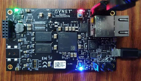
Some photos of the MicroZed powered up and attached with the carrier card:


1.2 Key Features:
SoC:
+ XC7Z010-1CLG400C
Memory:
+ 1 GB of DDR3 SDRAM
+ 128 Mb of QSPI Flash
+ Micro SD card interface
Communications:
+ 10/100/1000 Ethernet
+ USB 2.0
+ USB-UART
User I/O (via dual board-to-board connectors):
+ 7Z010 Version
+ 108 User I/O (100 PL, 8 PS MIO)
+ PL I/O configurable as up to 48 LVDS pairs or 100 single-ended I/O
Others:
+ 2x6 Digilent Pmod® compatible interface providing 8 PS MIO connections for user I/O
+ Xilinx PC4 JTAG configuration port
+ PS JTAG pins accessible via Pmod or I/O headers
+ 33.33 MHz oscillator
+ User LED and push button
2. Roadtest:
2.1 Working with PetaLinux out-of-box and Network Capabilities
2.2 Programming with Vivado
2.3 Using the PS-Pmod of the Carrier Card
2.4 Using the PL-Pmod of the Carrier Card
2.5 Using the Arduino Shield of the Carrier Card
2.1 Working the PetaLinux out-of-box and Network Capabilities:
2.2 Programming with Vivado:
This section deals with programming the MicroZed using Vivado. Showing the JTAG Access and Jumper Configurations
2.3 PS-Pmod - Processing System Pmod:
For testing the processing system Pmod, I will be using the custom-made Pmod character LCD. The video given below explains the working of character LCD in 4-bit mode and how the Pmod is built.
This video was a part of the course Summer of FPGAs - Building an Embedded System on FPGA which features the USB104-A7 Development board.
Pmod LCD Circuit:

One important point to note here is that the PS-Pmod is directly connected to the Processing System of the Zynq, thus it can be accessed only inside the processing system and cannot be accessed by the programmable logic.
To interface the Pmod LCD, first, we need to look at the MIO connections. It is not necessary to add any extra module to the block design because when the block automation is done for Zynq, the Fixed IOs connect the MIOs to the onboard components.
The mappings of the MicroZed MicroHeaders and the PS-Pmod are given below.

Now that we know the mappings, we need to think about the logic required to interface the LCD. Given below is the excel sheet which explains the logic.

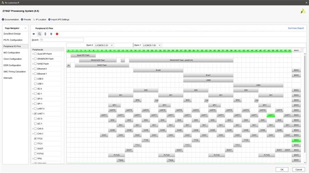
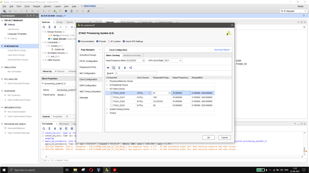
Configure the Zynq according to your requirements and disable unused peripherals.
| {gallery} Zynq |
|---|
|
Disable unused peripherals |
|
|
 |
Based on this logic the code for the Pmod LCD can be written as:
#include <stdio.h>
#include <stdlib.h>
#include "platform.h"
#include "xil_printf.h"
#include "xgpiops.h"
#include "sleep.h"


#define pmod_bank 0


XGpioPs Gpio;


// Initialize the LCD
void LCD_init();


// Send Commands to LCD
void LCD_Send_Command (unsigned char);


// Write Data to LCD
void LCD_Write_Data (unsigned char);


// Write a String to LCD (uses LCD_Write_Data function)
void LCD_Send_String (char*, int);


// Write a Number to LCD (uses LCD_Send_string function)
void LCD_Send_Number (int);


int main()
{


    init_platform();


    print("Program Started\n\r");


    int count = 0;


    LCD_init(); // Initialize LCD


    LCD_Send_Command (0x80); // Place cursor at Home (0,0)
    LCD_Send_String ("  Hello World!  ", 16);
    LCD_Send_Command (0xC0); // Place cursor at second line (1,0)
    LCD_Send_String ("   From Zynq!   ", 16);


    sleep(2);


    LCD_Send_Command (0x01); // Clear Display
    LCD_Send_Command (0x80); // Place cursor at Home (0,0)
    LCD_Send_String ("Time Elapsed:  ", 15);


    while(1) {


    LCD_Send_Command (0xC0); // Place cursor at second line (1,0)
        LCD_Send_Number(count);  // Write count value
        LCD_Send_String(" Seconds",8);
        count++;
        sleep(1);
    }


    cleanup_platform();
    return 0;
}


void LCD_init() {


    int Status;


    XGpioPs_Config *GPIOConfigPtr;


    GPIOConfigPtr = XGpioPs_LookupConfig(XPAR_PS7_GPIO_0_DEVICE_ID);


    Status = XGpioPs_CfgInitialize(&Gpio, GPIOConfigPtr, GPIOConfigPtr ->BaseAddr);


    //GPIO Initialization


    GPIOConfigPtr = XGpioPs_LookupConfig(XPAR_XGPIOPS_0_DEVICE_ID);


    Status = XGpioPs_CfgInitialize(&Gpio, GPIOConfigPtr,GPIOConfigPtr->BaseAddr);


    if (Status != XST_SUCCESS) {


    print("GPIO INIT FAILED\n\r");


    }


    XGpioPs_SetDirection(&Gpio, pmod_bank, 0xFC00);


    XGpioPs_SetOutputEnable(&Gpio, pmod_bank, 0xFC00);


LCD_Send_Command (0x02); // Initialize 16*2 LCD in 4-bit mode
LCD_Send_Command (0x28); // Configure LCD in 2-line, 4-bit mode, and 5x8 dots
LCD_Send_Command (0x0C); // Display ON Cursor OFF
LCD_Send_Command (0x01); // Clear Display
LCD_Send_Command (0x06); // Auto Increment Cursor


}


void LCD_Send_Command (unsigned char cmnd) {


unsigned char un, ln, rs, en; //Upper Nibble and Lower Nibble, register select and enable


int command;


un = cmnd >> 4;  // Shift right 4 bits and store upper nibble
ln = cmnd & 0x0F; // Mask and store the lower nibble


XGpioPs_Write(&Gpio, pmod_bank, 0x0000); // en=0, rs=0 & Write 0 to LCD Data Lines


rs = 0x0; //register select = 0 for sending command
en = 0x1; //enable = 1 to write data


command = (en << 15)|(rs << 14)|((un & 0x1) << 13)|((un & 0xE) << 9 );
XGpioPs_Write(&Gpio, pmod_bank, command);  // Send upper nibble where en=1, rs=0


usleep(2000);


command &= 0x7C00; // en = 0
XGpioPs_Write(&Gpio, pmod_bank, command);


command = (en << 15)|(rs << 14)|((ln & 0x1) << 13)|((ln & 0xE) << 9 );
XGpioPs_Write(&Gpio, pmod_bank, command);  // Send lower nibble where en=1, rs=0


usleep(2000);


command &= 0x7C00; // en = 0
XGpioPs_Write(&Gpio, pmod_bank, command);


}


void LCD_Write_Data (unsigned char dat) {


unsigned char un, ln, rs, en; //Upper Nibble and Lower Nibble


int data;


un = dat >> 4;  // Shift right 4 bits and store upper nibble
ln = dat & 0x0F; // Mask and store the lower nibble


//register select = 1 for sending data


XGpioPs_Write(&Gpio, pmod_bank, 0x0000); // en=0, rs=0 & Write 0 to LCD Data Lines


rs = 0x1; //register select = 1 for sending data
en = 0x1; //enable = 1 to write data


data = (en << 15)|(rs << 14)|((un & 0x1) << 13)|((un & 0xE) << 9 );
XGpioPs_Write(&Gpio, pmod_bank, data);  // Send upper nibble where en=1, rs=1


usleep(2000);


data &= 0x7C00; // en = 0
XGpioPs_Write(&Gpio, pmod_bank, data);


data = (en << 15)|(rs << 14)|((ln & 0x1) << 13)|((ln & 0xE) << 9 );
XGpioPs_Write(&Gpio, pmod_bank, data);  // Send lower nibble where en=1, rs=1


usleep(2000);


data &= 0x7C00; // en = 0
XGpioPs_Write(&Gpio, pmod_bank, data);


}


void LCD_Send_String (char *s, int len) {


while( len > 0 ) {


LCD_Write_Data (*s++); // Send each character in the string
len--;


}


}


void LCD_Send_Number (int number) {


int l, temp;
char buffer[5];


if(number == 0){


LCD_Send_String ("0", 1); // Send the number as string


}


else {


itoa(number, buffer, 10); // Convert number to string
temp = number;


for(l = 0; temp != 0; temp /= 10, l++); // Find length of the number


LCD_Send_String (buffer, l); // Send the number as string


}
}
Output after running the code:
2.4 PL-Pmod - Programmable Logic Pmod:
The PL-Pmod can be used both with the processing system and the programmable logic. In this section, I'll be adding a Quadrature Decoder Hardware module to the Programmable Logic of the Zynq.
Also, we need to use the AXI GPIO to interface between the programmable logic and the processing system.
Given below is a custom-made rotary encoder Pmod which is used for the PL-Pmod.

| {gallery} PL-Pmod |
|---|
|
Verilog Code for Quadrature Decoder |
|
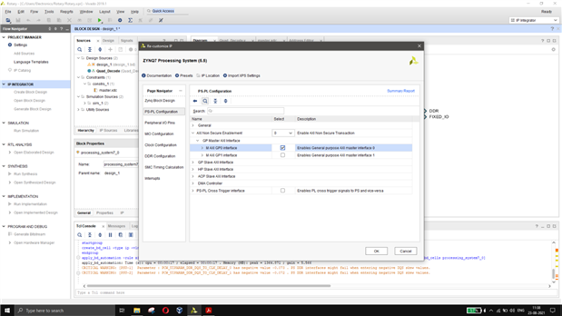
Add the Zynq IP |
|
Run Block Automation |
|
Configure AXI Master |
|
Configure PL fabric Clock for Quadrature Decoder |
|
Add the Quadrature Decoder Module and AXI GPIO and give connections |
|
Make External |
|
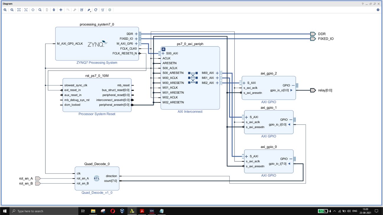
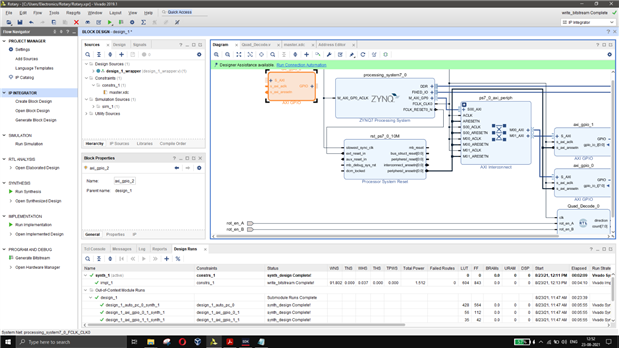
Completed block diagram |
|
Constraints File |
The changes in code for the above-mentioned project is given below:
int main()
{


    init_platform();


    print("Program Started\n\r");


    XGpio count, direction;


       // Initialize XGpio
       XGpio_Initialize(&count, XPAR_AXI_GPIO_0_DEVICE_ID);
       XGpio_Initialize(&direction, XPAR_AXI_GPIO_1_DEVICE_ID);


       // Set Direction of the GPIO
       XGpio_SetDataDirection(&count,1,0xFF);
       XGpio_SetDataDirection(&direction,1,0x1);


       // To store the count value and direction from GPIO Read
       int value = 0, direc;


       LCD_init(); // Initialize LCD


    while (1) {


    value = XGpio_DiscreteRead(&count,1); // Read Count Value
    direc = XGpio_DiscreteRead(&direction,1); // Read Direction


    LCD_Send_Command (0x01); // Clear Display
    LCD_Send_Command (0x80); // Place cursor at Home (0,0)


    LCD_Send_String ("Count = ",8); // Display "Count = " in LCD
    LCD_Send_Number (value); // Display Count value (number)


    LCD_Send_Command (0xC0); // Move to second line
    LCD_Send_String("Direction=",10); // Display "Direction=" in LCD


    if(direc) {


    LCD_Send_String("Right",5); // Display right if direction is 1
        }
    else {


    LCD_Send_String("Left",4); // Display left if direction is 0
    }


    usleep(500000); // Delay for 500ms


    }


    cleanup_platform();
    return 0;
}
Output:
2.5 Arduino Shield for Carrier Card:
For the Arduino Shield, I got the prototyping shield at a cheap cost. Given below is a photo of that.


A small bread-board can also be attached with the shield:

A relay can be added to this shield to demonstrate the working of the shield. For that, an AXI GPIO has to be added to the block design.
To write the constraints file we need to look at the user guide for the carrier card: (note that VCC and GND are interchanged (typo): Arduino Carrier Card for MicroZed

| {gallery} Shield |
|---|
|
Add an AXI GPIO to the block Design |
|
Only one-bit output for Relay (I'm using a single relay module) |
|
Run Connection Automation |
|
Update Constraints file |
Completed Block Design:
Now the code is modified such that the relay will be turned ON if the count value(8-bit Max. = 255) is above 100.
The modified code is given below:
int main()
{


    init_platform();


    print("Program Started\n\r");


    XGpio count, relay;


       // Initialize XGpio
       XGpio_Initialize(&count, XPAR_AXI_GPIO_0_DEVICE_ID);
       XGpio_Initialize(&relay, XPAR_AXI_GPIO_2_DEVICE_ID);


       // Set Direction of the GPIO
       XGpio_SetDataDirection(&count,1,0xFF);
       XGpio_SetDataDirection(&relay,1,0x0);


       // To store the count value and direction from GPIO Read
       int value = 0;


       LCD_init(); // Initialize LCD


    while (1) {


    value = XGpio_DiscreteRead(&count,1); // Read Count Value


    LCD_Send_Command (0x01); // Clear Display
    LCD_Send_Command (0x80); // Place cursor at Home (0,0)


    LCD_Send_String ("Count = ",8); // Display "Count = " in LCD
    LCD_Send_Number (value); // Display Count value (number)


    LCD_Send_Command (0xC0); // Move to second line
    LCD_Send_String("Relay : ",8); // Display "Direction=" in LCD


    if(value > 100) {


    LCD_Send_String("ON",2); // Display right if direction is 1
    XGpio_DiscreteWrite(&relay, 1, 0x1);
        }
    else {


    LCD_Send_String("OFF",3); // Display left if direction is 0
    XGpio_DiscreteWrite(&relay, 1, 0x0);
    }


    usleep(500000); // Delay for 500ms


    }


    cleanup_platform();
    return 0;
}
Output:
Review:
The User Guides are very easy to use and informative. The PS-Pmod has its own advantages and disadvantages. The advantage is that it can be directly interfaced with the Zynq Processing System. The con is that it cannot be used to connect to the PL fabric of the Zynq. The Carrier card is ideal for designs that use Arduino Shields. The 128Mb of QSPI flash is sufficient to accommodate the PetaLinux for Embedded Linux-based designs. The PL-Pmod gives users the flexibility to use it with both Processing System and the programmable logic fabric. The Power planning is also excellent for the carrier card, powering up the carrier card is sufficient as the MicroZed has its power rails connected to the carrier card. The Linux that boots out-of-box has all the required drives for implementing protocols such as I2C, SPI, etc. When booted with PetaLinux, the microzed can be accessed both via the UART and the SSH. This gives us the flexibility of using it via the network for IoT applications. The USB Port in the MiroZed can be used to connect a camera or any other USB device with an appropriate driver.
Even though I'm a beginner and using the Zynq device for the first time, I didn't feel any difficulty in getting started with the designs for this road test. This is one of the most versatile FPGA-SoC development platforms I've ever used. Configuring the Zynq IP was also very easy in the Vivado tool. Overall, my experience in using this product was great!
Future Ideas:
I am planning to port PYNQ image for MicroZed, I'll update this roadtest page once that is done.
References:
AVNET Website and MicroZed Chronicles by Adam Taylor.
Acknowledgments:
First of all, I thank Randall for giving me this opportunity. Secondly, I thank Daniel for helping me with the shipment.
Last but not the least, I thank Avnet for sponsoring this road test.


Top Comments
Good road test report.
DAB
Yeshvanth,
I saw your email in my inbox so I went over and read your review. A fine job. Very informative. All the visuals really help the reader in understanding what you did. I appreciate your effort…