RoadTest: Tiva DK-TM4C129x Connected Development Kit
Author: michaelwylie
Creation date:
Evaluation Type: Evaluation Boards
Did you receive all parts the manufacturer stated would be included in the package?: True
What other parts do you consider comparable to this product?: null
What were the biggest problems encountered?: Documentation was the biggest problem. There is so much documentation for this product it is difficult to find the information you require.
Detailed Review:
Video Summary
This video is a shortened summary of my experience with this development kit.
.
Full Review
Summary
I chose to evaluate this product based on a simple project. The Tiva DK-TM4C129x Connected Development Kit was impressive and disappointing at the same time. The PCB design is excellent, and the board is easy to manipulate. One of my favorite features is that the real time clock is buried inside the microcontroller. I was disappointed that a digital to analog converter was not included in the kit. A bit of tricky soldering is required in order to achieve some low-power mode capabilities. The most frustrating aspect of this evaluation was locating the Application Programming Interface (API), which was instead referred to as the Peripheral Driver Library (PDL). This is a complicated development kit, and I would not recommend it for beginners. Maybe two months of part-time coding and reading isn't enough to fully appreciate this development kit.
TM4C129x Proposal
You can read all about the Tiva DK-TM4C129x Connected Development Kit capabilities from the main Road Test page, but it's practically an entire embedded system with all kinds of peripherals. My proposal was to build a simple pulse counter and store the count data on the microSD card. I think it's interesting to rate a product based on how quickly you can make something simple work because, in industry, time is money. Development kits should save company time and increase productivity and efficiency.
My Dev-Kit Experience
I am the Senior Electrical Engineer for a small company, where I primarily design PCBs and embedded systems. I routinely evaluate and choose which products we should use in our next design. This was my first introduction to 32-bit microcontrollers, as I typically use 8-bit micros. It was also my first time using an ARM architecture and I knew there may be a steep learning curve, so I started reading before the development kit arrived. Although I have lots of experience with TI products, this was my first time using a TI microcontroller, and I had high expectations for this kit.
First Impressions
The box design is very attractive - kudos to the graphic guys. The kit included 3 USB keys with copies of the installation files; I thought that was nice, since they're inexpensive and easy to misplace. The kit did NOT include a microSD card, an inexpensive item that should have been included (and is included in some dev kits). The PCB layout is practical with sufficient space between connectors. Nearly every signal is jumpered, which means you can easily disconnect their default design and interface your own signals. The rubber feet on the board will actually grip your desk or workbench rather than slide all over the table when you're trying to hook up other devices. Some of the pads are gold plated which looks great and prevents oxidation. There are also lots of test points for clipping your scope probes onto.
Initially, I thought the LCD was upside down. I instinctively held the board like a calculator with the LCD at the top, but when I powered the board, the Texas Instruments logo was upside down. Later, I realized the LCD is ideal at the bottom of the board. This way you can control the touch screen without reaching over the expansion ports, which was obviously part of the design.
The default program that loads is a weather display, which requires an internet connection via ethernet. I don't keep a router on my desk and my computer is wirelessly connected to the internet, so I just loaded a different example program. Overall this kit seems impressive, as you can see for yourself in Figure 1.


Figure 1: DK-TM4C129x Connected Development Kit.
Example Programs
It takes about an hour to install all the different programs and libraries that come on the USB key. I installed the components required for Keil µVision first so I could download the example programs while everything else installed. I loaded the Hello World program and wasn't surprised to see the screen displaying the historical salutation to me. Next I loaded Blinky, another favorite amongst example programs and an LED started periodically blinking. In the example directory I spotted a program called Calibrate, so I loaded it and determined it was a calibration program for the touch screen. That seemed useful, except the program starting picking up presses that were not happening and finished calibrating before I had a chance to touch the screen. I reloaded this program a few times and it responded the same way every time. I tried out some of the other programs while the installation finished. Later, I tried the Calibrate program again and this time it worked. I'm unsure of why it initially did not work.
Counting Pulses
I didn't have a pulse generator at my home, so I decided to use an interrupt driven counter to represent the pulses. I modified Blinky to be interrupt driven, and rerouted the data to be displayed on the LCD. With approximately 5 hours of reading and internet searches, I had simulated pulse counting - which isn't too bad considering it was a brand new platform. The numbers on the LCD in the default font looked a little weird to me, even when using the built-in libraries for displaying a single character. There seems to be some residual pixels on because it's not clearing the proper portion of the LCD, shown in Figure 2. I'll have to do some research on clearing portions of the LCD. My guess is that their default font does not use monospaced numbers.

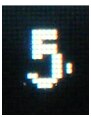

Figure 2: Default Font Numbers on the Display. Lingering pixels from previous numbers are not cleared before the next number is displayed.
Difficulty Reading Ports
Now, real pulse counting triggers an interrupt from an input pin, so I began modifying the program to interrupt on a button press. I looked in Blinky because I knew a General Purpose Input/Output (GPIO) pin was configured as an output to drive the LED, and I found the following implementation:
while (TRUE)
{
Turn off a bit on the GPIO
delay
Turn on a bit on the GPIO
delay
}
The pin being used was called GPIO_PORTQ_DATA_R and was defined as an address in memory. I decided that I wanted to read pin PN3, which is the 'up' key on the dev kit, and I began searching for the required address. This took way longer that it should have. I read through the microcontroller documentation, and it wasn't clear which address to read. Only after an extended period of reading through TI community posts was the answer clear. These TI users do not recommend that beginners read ports this way. The preferred way to read a GPIO is with the following commands:
SysCtlPeripheralEnable(SYSCTL_PERIPH_GPION); //Enable the GPIO
GPIOPinTypeGPIOInput(GPIO_PORTN_BASE, GPIO_PIN_3); //Set as input
GPIOPinRead(GPIO_PORTN_BASE, GPIO_PIN_3); //Read GPIO
I realize the GPIO in Blinky is configured for speed and the preferred method is slower, but this example code includes a method of reading GPIOs that is not standard with the libraries provided and confusing to beginners. Eventually I was able to make the button press trigger an interrupt, but this extra research nearly doubled my development time. The most frustrating part of this experience was finding the API for the kit. I searched through several documents, including the 2182 page microcontroller datasheet and I couldn't find an API. Eventually I discovered, by accident, that TI doesn't call their API by that name, instead they call it a Peripheral Driver Library (PDL).
No DAC
While contemplating creating a pulse generator, I thought about designing a touch screen function generator with this dev kit. Unfortunately this kit doesn't seem to have a digital to analog converter (DAC), and if it does I'd be concerned with why it isn't mentioned in the User Guide's table of contents or why a search for DAC in the microcontroller documentation returns 0 results. I thought there may be a good reason for not including a DAC, so I examined the microcontroller peripherals. This microcontroller has three built-in comparators and the comparison level can be set internally. The internal level is shared amongst all three comparators, so unless your events all have the same threshold or you can change the internal level fast enough, 2 of those 3 comparators may be redundant. This kit should have a DAC; users should be able to put a different DC voltage level on each comparator input.
Clocks
There is no visible Real Time Clock (RTC) chip on the dev-kit board. The RTC is buried in a hibernation module inside the microcontroller. I love this feature, and I really like the hibernation library that comes with the board. It made setting up a clock for the embedded system extremely easy.
Power Reduction Applications
While reading the user guide I noticed the following text:
"The sleep mode of the 3.3V regulator can be used by moving the 2.2-kΩ resistor from R2 to R16, which enables the low power mode of the switcher (U7) when TM4C129XNCZAD (U1) goes into hibernation." These positions are shown in Figure 3.

Figure 3: A picture I took showing R2 and R16.
I'm really good at soldering and I would not hesitate to solder on a dev-kit, but if I tried to remove that component there's a good chance it would pop out of my squeezing tweezers and get lost. Nearly everything else on this kit was jumpered, and this should have been as well since energy conservation is a concern in any portable or handheld device design.
Edit: Had to re-upload some pictures. An Element14 website update thing.


