RoadTest: Tektronix DMM4020 Digital Multimeter
Author: Zad
Creation date:
Evaluation Type: Independent Products
Did you receive all parts the manufacturer stated would be included in the package?: True
What other parts do you consider comparable to this product?: Fluke 8808A Agilent 34405A Agilent U3402A Refurbished HP / Agilent HP 3456A
What were the biggest problems encountered?: No huge problems. The dual display is somewhat of a gimmick rather than a usable feature. Ranging can be slow and noisy. No capacitance range.
Detailed Review:
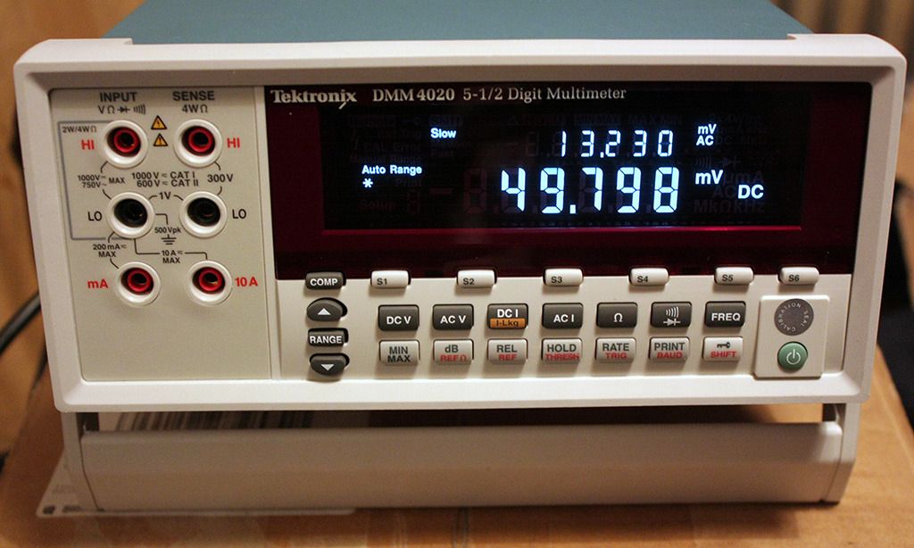
Tektronix DMM4020 Benchtop 5.5 Digit Multimeter
- Long Term Review and Update
It is now over a year since I published my review of the Tektronix DMM4020 5.5 digit bench meter, so I thought it was about time for an update. If you are looking for stats and performance data, I would refer you back to both my original review and the official Tek data. I don’t have access to a calibration lab, so can’t say how closely the meter matches its published specification. However, I can say that I have no reason to disbelieve their claims, other than to say the manufacturers may be being a little cautious. It feels absolutely rock-solid in use.
I was hoping to record a video review, unfortunately Santa Claus didn’t deliver a video camera. Bah! However, this is a bench meter not a supercar from Lamborghini, so a bunch of still photos will do nearly as well.
I will start off by going through one or two little “niggles” that have cropped up, and then have a good look around inside – breaking the calibration seal! I think it is important for engineers to know exactly what gear they are getting.
Introduction
The Tektronix DMM4020 is actually a Fluke product – The 8808A. Both companies are owned (along with Keithley Instruments and many others) by The Danaher Corporation, and they are clearly increasing their platform-sharing. Farnell / Element-14 sell both items, with the Fluke 8808A being slightly cheaper. Importantly though, the DMM4020 has a three year warranty, versus the standard 1 year with the Fluke item. Personally, I would pay the small amount extra and go with the three year option - i.e. the DMM4020. In theory the reliability of a product follows the classic “bathtub” curve, with most failures occurring soon after manufacture/initial use and right at the end of the product life. I think most engineers will know that products actually fail at the worst moment, and the week after the warranty expired! The extra outlay for 2 years peace of mind is relative peanuts and for me is a no-brainer.
A note about the photograph above: The apparently spurious value being displayed is a function of the very high impedance measurement available on the voltage ranges. When connected in circuit, this disappears.
Criticisms
Bench meters tend to be used in a slightly different way to “hand held” meters. Hand helds are usually used for ad-hoc metering with free probes, whereas bench meters are more commonly connected for a period of time. It would have been appropriate to at least include a crocodile clip ground wire, and preferably a full pair of clip probes. At a current retail price of £539 it wouldn’t be much to ask.
I think that in a machine of this specification, being able to measure capacitance would not be unreasonable. Okay, so it wouldn’t be able to approach 5.5 digit resolution without major changes to the system architecture, but capacitance measurement is common on the majority of hand held meters now, and it does feel like somewhat of an omission here. The Agilent equivalent meters do indeed support capacitance measurement.
The only other real issue is in the dual display. Like many middle and higher end meters, the DMM 4020 can display two measurements at a time. This is restricted to certain pairings; for example, you can measure DC voltage and DC current together, or DC voltage and AC voltage (power supply ripple, noise etc). Unfortunately, the meter only has one ADC channel, and must switch between the various configurations. This results in an incessant CLUNK … CLUNK … CLUNK … CLUNK from the configuration relays. It is no huge problem, but it slows down measurement speed and can drive an engineer up the wall after a time.
Relays are certainly the best option for switching a bench meter; semiconductor switches cannot get anywhere near the level of isolation and low impedance provided by traditional electromechanical relays, but they are slow, noisy and have a finite lifespan.
Teardown.
To call it a teardown is probably an exaggeration. Taking the top off and having a look inside would be closer to the truth. Lets face it, most engineers have been doing this since they could hold a screwdriver!
Despite the inevitable calibration warning seal, it is obvious that the unit is designed to be opened and serviced. Mainstream consumer electronics items are usually designed for ease and cheapness of assembly, being a nightmare to take apart and reassemble. Not so with the DMM4020. Remove four short Philips screws and the pressed steel cover slides off. Incidentally, the screws fit into metal threaded inserts, and have a small amount of threadlock on them. I didn’t go any further than this, so was unable to inspect the underneath of the PCB. It appears to be equally easy to access though, with no specialist security screws or clips. All the power and PCB inter-connectors are standard types and easy to use.
Incidentally, there might be a calibration warning seal, but there are no trim pots to adjust. That means no trim pots to go dirty, noisy, age, or drift as they absorb moisture. This is definitely more a 21st century design than retro VFD look would perhaps have you believe.
I have annotated the main areas:
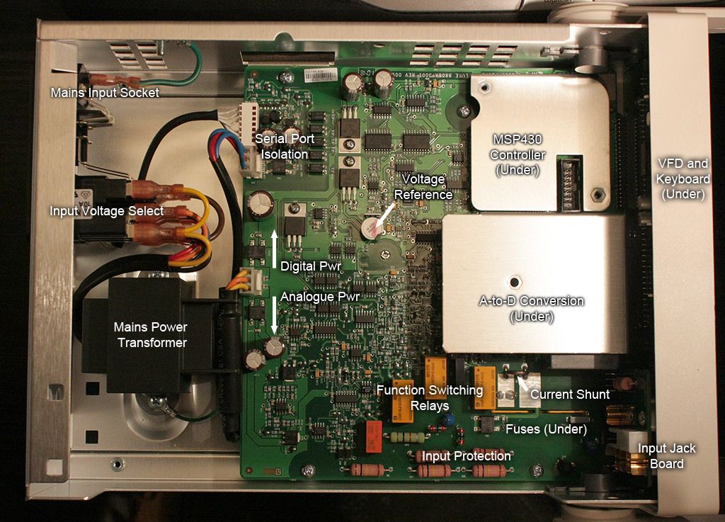
As you can see from the photograph, it is very conventional PCB technology, with a mixture of through-hole and SMD devices. The main PCB is up to revision 9 and copyright 2007, so definitely a mature product! The PCB itself is a multi-layer type – the designers have thoughtfully provided a window in the PCB which brings out a layer number. Always a nice touch in multi-layer designs.

Here is the rear of the front panel containing the Vacuum Fluorescent Display (VFD) and pushbuttons. Manufactured by Samsung. It has quite a large multi-tapped transformer, presumably to generate the necessary VFD voltages. A potential source of EM noise, they have shielded the close-by sensitive sections. VFD can look rather retro (i.e. old fashioned) in comparison to LCD and OLED, but there is no denying the superb clarity and response speed.

The first thing you see on the main PCB is the voltage reference, right in the centre of the board. The classic National Semiconductor LM399H inside a thermal jacket. The voltage reference is at the heart of any multimeter and this is a well known device with an excellent track record for reliability and accuracy, especially when “burned in”. The LM399H is oven controlled, and the custom high-precision ceramic resistor pack used in the buffer op-amp is mounted directly next to it for thermal stability.

As you can see from the photograph, many of the resistors are in the light blue packaging, denoting a close tolerance. All the ICs that I could see were major brands, with quite a few Maxim Max4053s in evidence (SPDT mux/demux switches).
Peeking underneath the PCB via the fuse access just reveals a few surface mounted capacitors. There is, however, an area of aluminium shielding that was impossible to see beneath without further disassembling the meter.

Under the alloy shields are the microcontroller and the A-to-D system. The controller is a ubiquitous MSP430. This may seem a little restrictive and slow for a bench meter, and I’m sure current consumption isn’t an issue in a bench meter, but Tek (okay, Fluke) will have a set of instrument design engineers who are very familiar with MSP430s, and it would be foolish to change architectures just for the sake of it. You will note that the MSP430 has a full JTAG socket exposed, not just bare PCB header. Again pointing to the designed-in maintainability.
Under the second alloy shield is the ADC and accompanying AD627 precision RMS converter. I say the ADC is under there, but without removing the shield (and hence the entire PCB) it was impossible to see any more part numbers. This photo shows the difficult visibility:

Power Supply.
As you can see from the main photograph, it is very conventional transformer based linear stuff here, with no electrically noisy switched mode stuff to get in the way of your measurements. It appears to have separate windings for the analogue and digital sections. Indeed, the analogue and digital processing sections are nicely separated. The RS232 interface section also has its own windings to ensure total electrical isolation, with a good isolation gap. The electrolytic capacitors are all excellent quality Nippon Chemi-Con brand KMG series in the classic brown coating. Definitely no penny-pinching there. Below is a close-up photograph of the RS232 interface area:

Input and protection.
The 4mm front panel sockets are all mounted on a daughter board (showing revision 7). Interestingly, the 2-wire and 10A sockets are both split connectors, with the sturdy gold plated metalwork mounted on the rear of the PCB. The 4-wire and mA connectors mounting from the front. The soldering on these is top quality work and worth a close-up photo. It is notable that the PCB is attached to the front panel with a specially designed nylon clip rather than screws. Presumably this distributes the physical load better. The mA socket also seems to be shielded from the potentially high-voltage traces via a routed-out slot and plastic shield.

There is a handful of protection components (varistors and spark gaps) on the top of the board, but nowhere near as many as you might see in a hand-held meter, which is curious. Maybe they are less prone to abuse, or are inherently more robust due to their design. High rupture capacity (HRC) fuses are mounted underneath the board and are accessed through a small hatch in the base of the unit. The small plastic unit peeking through the routed hole is the fuse cover, with the current fuse mounted inboard, and the voltage fuse mounted towards the outside of the enclosure. It is worthy of note that the DMM 4020 is only Cat I / II protected. Perfectly fine for bench work, but not for use on distribution panels, mains feeds etc. It simply isn't intended for that sort of work.

Unlike hand-held meters, where range selection is mostly done by a mechanical rotary front panel switch, bench meters use good old electromechanical relays (the yellow and orange boxes visible in the photo above). Semiconductor switching simply cannot come close to these in terms of isolation and low impedance. They make an audible “clunk” as you change range and gain settings. This is perfectly acceptable in normal use, but when you are using the dual measurement capability the endless clunking can get rather annoying.
Conclusion:
As things turned out, I ended up not using the DMM 4020 in quite the way I had expected. The intention was to have it sat on the bench and for it to be used as a replacement for my hand held test gear, mostly in troubleshooting during development. Maybe it is down to habit, but I have continued to use the hand-held meter for repair and general troubleshooting work. Repair rarely (if ever) requires 5.5 digit accuracy, memory functions or computer control and, despite the designed-in isolation, I never feel quite as secure as using a rubber and plastic enshrouded free standing meter.
I have to say though, it really has changed the way I design and develop. Having that extra usable resolution (which would be no good without a good quality stable voltage reference) really gives an extra layer of insight as to how components and circuits perform. Being able to log relatively small changes over a long period of time allows me to apply more science to the development process too. I don't think I had appreciated just what I was missing with a 4.5 digit meter. Allied to that the ability to connect with LabView and similar PC analysis software, and I feel it has put more more in control.
I look forward to being able to do much more work with LabView software in the future too, but it does rather feel like a steep learning curve at the moment. Doing simple logging and graphing is extremely easy however, and I would encourage any owner to try it.
If you are a hobbyist with an interest in metrology, instrumentation, or simply showing off, then jump on to Ebay and buy yourself a calibrated 6.5 digit meter. Enjoy having it sat on a shelf looking big and expensive. If, however, you are a professional engineer (or a scientist for that matter) and rely on your test gear to work for a living, then I have no hesitation in recommending the DMM4020. Sure, it isn’t exactly cheap, but you get what you pay for, and it is a seriously good tool to have around. Right now, I don’t know how I managed without one.
That concludes my update. My thanks go out to Farnell / Element14 for providing this remarkable piece of equipment. If anyone has any questions or comments then feel free to post them here in the forum, or drop me an email, where I will be happy to answer them.
Postscript: If anyone has a schematic diagram for a DMM 4020 or 8808A then I would love to see a copy. My Google skills seem to have let me down here.
Mike Cowgill, January 2013.
Design Engineer, Digital-Wizardry.co.uk


