RoadTest: TIDA - 01069 Adv. Motion Detector with PIR Sensors
Author: mconners
Creation date:
Evaluation Type: Evaluation Boards
Did you receive all parts the manufacturer stated would be included in the package?: True
What other parts do you consider comparable to this product?: None. This is a reference design for a new approach
What were the biggest problems encountered?: null
Detailed Review:
Man, I have to say, this was one of the funnest Road Tests I have ever done. Huge thanks go out to Element 14 and Texas Instruments for selecting me.
I have a background in DSP. From about 1986 to 1998 I worked for a company that built systems that digitized a big chunk of the radio spectrum, downconverted it, demodulated signals we found in that spectrum, and looked for patterns via software. FFTs were part of my daily life. I spent a lot of time looking at spectrum analyzers and o'scopes, then looking and the same signals after they had run through our process to see if we were doing a good job. I had quite the practical mastery of converting signals from the analog domain to the digital domain, then from the time domain to the frequency domain. That was a very fun period of my life. I really enjoyed seeing what computers were capable of in terms of interfacing and understanding the analog world around us. After a while I moved on to other jobs in different specialties of software and I thought those days were long behind me. I missed it.
I had the opportunity to read some documentation about the TIDA-01069 reference design and what I saw what they were doing, when I read their white papers and viewed their analysis, I was sent right back to that earlier time in my career, and I just knew I had to do this road test. They spoke of continuous wavelet transforms (CWT), and how they could use those to get a time vs. frequency plot. That stuff was only in Academia back when I was implementing practical applications for FFTs for signal recognition and analysis. I even looked back in my old textbooks and saw no mention of CWT. As I read more about the technology, and how you can use the CWT to train machine learning algorithms to look for patterns, I was enthralled. I still have a lot to learn about machine learning, but this road test has given me a great introduction to the initial steps to start me on my way.
The Hardware:
The TIDA-01069 was designed to interface to a standard booster pack pinout. So if you are familiar with the TI LaunchPad series of development boards you are well ahead of the game. I took the EdX MOOC, Embedded Systems -Shape the World, that is advertised here on Element 14 and it is based upon a standard TI LaunchPad, so I had that. My exposure to the board for the class prompted me to purchase a CC3200 launchpad, which has built in wireless, and an MSP 430 launchpad, so I was pretty familiar with the LaunchPad series, and the Arduino/Wiring environment for those boards, Energia. I was fully prepared to complete this test using the CC3200, but they surprised me. Included with the reference design board was an MSP 432 based launchpad. That was a very pleasant gift that I was not expecting.
MSP432P401R LaunchPad:
The MSP432P401R is one of the TI Launch Pad line. This is a series of microcontrollers on boards with a standard pinout. They are available in 20 pin and 40 pin configurations, although the 40 pin modules can facilitate the 20 pin peripherals. The Launch Pad series are reasonably priced and well documented. Programming the devices is possible using a variety of tools and IDEs. ARM Keil MDK, TIs Code Composer, IAR Embedded Workbench, GCC, and Energia. Energia is a fork of the Arduino IDE and provides a relatively easy transition from Arduino to the more powerful ARM chips. Further easing the transition is the fact that many Arduino libraries have been ported/recompiled to work on the Launch Pad series. Often porting a program written for Arduino is greatly simplified.
The peripherals designed for the launch pads are often mounted on Booster Packs. Many of the Booster Packs are community designed and are available for a wide variety of purposes.
The capabilities of the MSP432P401R are as follows:
48MHz 32-bit ARM Cortex M4F with Floating Point Unit and DSP acceleration
Power consumption: 80uA/MHz active and 660nA RTC standby operation
Analog: 24Ch 14-bit differential 1MSPS SAR ADC, Two Comparators
Digital: Advanced Encryption Standard (AES256) Accelerator, CRC, DMA, HW MPY32
Memory: 256KB Flash, 64KB RAM
Timers: 4 x16-bit, and 2 x 32-bit
Communication: Up to 4 I2C, 8 SPI, 4 UART
TIDA-01069 Reference Design:
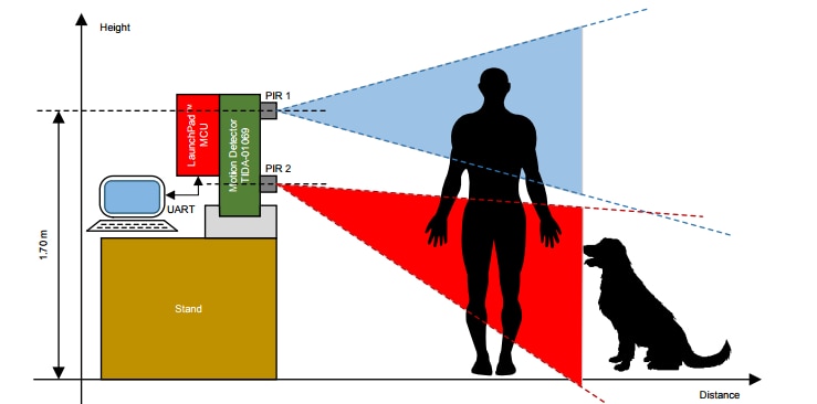
The analog signal path is really the meat of this design. The data from the 2 PIR sensors is condtioned and split to follow 2 parallel paths, one path to generate interrupts when there is a motion event, the other to capture the data in a digital format for analysis. The PIR sensors are arranged on the board and fitted with fresnel lenses optimized for receiving IR energy in a manner that is helpful for detecting motion in 2 different pathways. A high path and a low path. In this manner you can determine additional characteristics about the subject of the motion event.

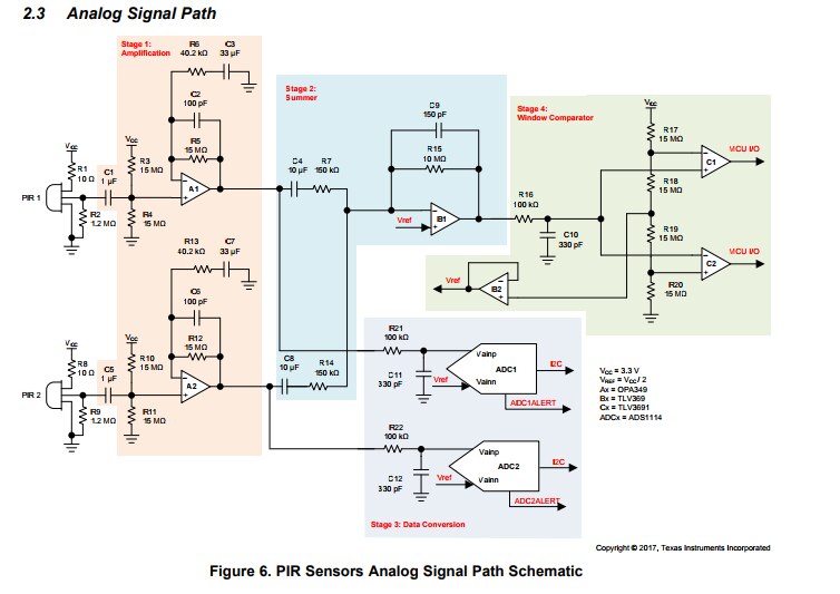
The above diagram is directly from the documentation for the board. The analog signal path is broken down into 4 stages.
1) Amplification
2) Summer
3) Data conversion
4) Window comparator
Amplification:
PIR sensors typically output very small AC signals, in order to be useful the the amplitude of the signal have to be increased. This is the function of the amplification circuit.
Summer:
This section of the design combines the two signals from the PIR sensors and conditions them for the Window comparator.
Window comparator:
This part of the circuit is intended to take the output of the summer and generate interrupts to be processed by the microcontroller. This part of the design that I found to be unstable. The interrupt lines were in constant flux, which I discuss later, they were not usable as interrupts.
Data Conversion:
OK. This is the fun part, the PIR signals travel a parallel path into the A/D converters at the same time they go to the summer stage. There are 2 14 bit A/D converters on this board, each set to separate I2C addresses to allow the microcontroller to access them separately. There are interrupt lines available to alert the microcontroller when a conversion has been completed, but I found them unecessary as I was capturing a set number of samples over a distinct period of time so it was adequate for me to simply poll the A/D converters and grab the last successful conversion result.
In addition to the analog signal path described above there are also a few other components mounted on the board to aid in the process of detecting false triggers. There is also an HDC1010 Temperature and Humidity sensor. Rapid changes in ambient temperature can be interpreted as motion in an IR sensor, this device is available to allow you to monitor the condition of the environment the board is deployed in and gives you one more piece of data to use when making the determination as to whether you have detected a valid motion event. Also an OPT3002 light sensor. Rapid variations in lighting can also trigger a motion event, so again, more data, better decisions.
The Software:
Prior to receiving the kit I looked around on the TI site quite a bit and found no drivers or software for this board. I started collecting the data sheets for the programmable components on the board and started writing drivers. I started simple with the OPT3002 light sensor, I found some code for a similar sensor and adapted it for my needs. I created an Arduino style c++ library and added it to energia. Next, using the OPT3002 driver as a skeleton, I then created a similar driver for HDC1010 Temperature and Humidity sensor. Finally I started on the A/D converter. The ADS1114 is part of a family of A/D converters by Texas Instruments. It is the middle tier of capabilities between the ADS1113 and ADS1115. The biggest difference between the ADS1114 and the ADS1115 is that the ADS1115 is multi channel and has a built in multiplexer. All three devices share a programming guide so the interface between the devices is similar and the differences are pointed out in the guide. I found a driver by adafruit for the ADS1015, which also had code for the ADS1115 as well. I was able to use this code and tailor it specifically for the ADS1114. I was then on my way.
After receiving the kit, I opened energia and wrote some quick sketches to test out my driver libraries. Once I determined that they were working well, it was time to start solving the problem at hand. My first task was to try to capture data from the board based on sensed motion. I added interrupt handler routines to capture data based on the rising edge of the outputs of the window comparator circuitry. Much to my dismay these lines were constantly in motion. I don't know if there is a flaw in the design or if there is a defect in my board. Fearing noise from the microcontroller board, I removed the TIDA-01069 from the launch pad and hooked a scope to the interrupt pins. They were never stable. I even wrapped the device in a towel and put it in a cooler. That didn't help. This was a significant blow to my plans. If I could not control when the device was triggered, and it was constantly collecting, there would be no feasible way to correlate captured samples with specific activity performed in front of the sensor to allow for machine learning. When I hooked the device back to the microcontroller and ran my program, I repeated the cooler test and the device triggered repeatedly. The window comparator circuitry needs to be reviewed by TI to determine if it is correct. Ultimately I was able to get around this problem by digging in my toolbox and finding a Parallax PIR sensor and hooking it up to the board as well. I switched the interrupt handler to trigger on the output of this PIR sensor and I was able to control when my data collection would start. This limitation is really only important when collecting data to train your machine learning algorithm. As I mentioned earlier it is essential to correlate activity to samples in order to train the system. Once the algorithms have been determined and a sufficient number of samples have been collected, continuous collection of data from the sensors and comparison to the stored sample signatures would not be affected.
I wanted to be able to place this device in a remote location, the length of the USB cable connecting to the LaunchPad was a limiting factor. This would have been a case when wireless connectivity of the board would have been a big plus. I decided instead to connect it to a Raspberry Pi via usb and allow the Pi to handle data transfer. Based on data in the documentation for the pir sensor and the subsequent data analysis in MATLAB, they had collected 20 seconds worth of samples at 64 samples/second. I modified my energia sketch to set each of the A/D converters to a sampling rate of 64 samples/second, and upon interrupt, to collect data for 20 seconds. After data collection was complete, I output the data via the serial port in JSON format as :
{
"adc": "<SENSORID>",
"samples": [sample1,sample2,sample3,...,sample1280]
}
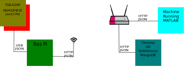
I wrote a python program on the raspberry pi to monitor the USB port, log anything that wasn't JSON data to the console, and post the json stream to a web service running on my desktop.
On the desktop, I wrote a simple microservice in Go that accepted a JSON payload via an HTTP POST , added a unique Id (the unix time that the message was received) and stored it in a MongoDB database. I then added some additional methods to query that webserver to retrieve a list of URLs to retrieve the individual records, and a method to retrieve the individual records in JSON format.
Once this was complete, I was able to write a program to run in MATLAB to retrieve an individual record from my web service, plot the data in the time domain, perform a CWT on the data and plot the Magnitude Scalogram, and plot the results of an FFT on the data.
A polyglot system indeed. I mixed C/C++, python, Go, and matlab into a single system. Each language was particularly well suited to the task. I had never stored data in MongoDb before, and definitely not in the Go language, and the whole thing was up and running with the minimal functionality that I needed in just a few hours.
System Diagram:
Conclusion:
See comments below.
References:
These are the core resources used when performing this road test. Within these documents you will find greater detail about the theory of operation and design goals of the project. You will also find links to scematics, gerber files and other documents relevant to the module under test.
http://www.ti.com/lit/ug/tiducv3a/tiducv3a.pdf
MSP-EXP432P401R SimpleLink™ MSP432P401R LaunchPad™ Development Kit | TI.com


