RoadTest: Infineon 3-Phase Motor Drive EVB with FOC
Author: MARK2011
Creation date:
Evaluation Type: Development Boards & Tools
Did you receive all parts the manufacturer stated would be included in the package?: True
What other parts do you consider comparable to this product?: Inverters for low power motors; DesignDRIVE Development Kit IDDK v2.2.1 by Texas Instruments
What were the biggest problems encountered?: Unfortunately - many In my opinion documentation although clear and quite voluminous doesn't give enough support the roadtested kit. Despite many attempts, the motor cant be run using the driver board. The software isn’t stable. - Above issues, adding the awareness of dealing with high voltage made the work truly risky.
Detailed Review:
It would be impolite to start from complaining without thanks for selecting me for the roadtest.
Thank you Element14, thank you Infineon for invitation and trust.
On the other side, I have to admit, the roadtest was full of challenges but also disappointments. I don't want to complain too much and feel sorry for myself but it was the most frustrating roadtest.
Nevertheless, let me move to the beginning
After a long delay caused customs clearing issues, the board with the debugger and finally also the fan were successfully delivered.
At the beginning everything seemed to be perfect. In addition to devices I was provided with a report from the individual test of my board.
I prepared for the roadtest surfing infineon sites with documentation of our kit, looked at foras where users share impressions and remarks concerning imotion solutions etc.
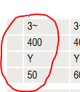
I was sure of good support, clarity and mostly safety first - as I planned to deal with a 3X400 AC net.
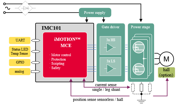
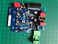
Main components of the driver board
the heart: IMC101T-T038
iMOTION™ motor controller with Motion Control Engine
PMSM/BLDC motor controller with integrated script engine
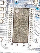
iMOTION™ IMC100 motor controller with Motion Control Engine (MCE 2.0). The IMC101T-T038 is a flexible control solution for variable speed drives.
It performs sensor less field oriented control (FOC) for a permanent magnet synchronous motor (PMSM).
The integrated script engine (small virtual machine) provides application flexibility by running customer scripts.
2ED28073J06F 600V EiceDRIVER half-bridge gate driver IC
https://www.infineon.com/cms/en/product/power/gate-driver-ics/2ed28073j06f/
600 V half-bridge gate driver IC with integrated bootstrap diode with typical 0.02 A source and 0.08 A sink currents in DSO-8 package for driving MOSFETs including fast body diode CoolMOS PFD7 super junction MOSFETs and IGBTs.
The 2ED28073J06F is a high voltage, high speed power MOSFET and IGBT driver with dependent high and low side referenced output channels. Proprietary HVIC and latch immune CMOS technologies enable ruggedized monolithic construction.
The logic input is compatible with standard CMOS or LSTTL output, down to 3.3 V logic. The output drivers feature a low di/dt output stage optimized to drive CoolMOS™ PFD7 in motor drive applications.
The floating channel can be used to drive N-channel power MOSFETs or IGBTs in the high side configuration which operates up to 600 V.
IPN60R1K5PFD7S 600V CoolMOS MOSFETs
Complements the CoolMOS™ 7. The IPN60R1K5PFD7S in a SOT-223 package features RDS(on) of 1,500mOhm resulting in low switching losses.
The 600V CoolMOS™ PFD7 SJ MOSFETs come with an integrated fast body diode ensuring a robust device, reducing bill-of-material.
This product family is tailored to ultrahigh power density as well as highest efficiency designs. The products primarily address ultrahigh density chargers, adapters and low-power motor drives.
The 600V CoolMOS™ PFD7 offers improved light- and full-load efficiency over CoolMOS™ P7 and CE MOSFET technologies resulting in an increase in power density by 1.8W/inch3.
XMC™ Link – Isolated Debug Probe Based on SEGGER J-Link Technology
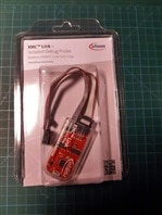
XMC™ Link is an Isolated Debug Probe for all XMC™ Microcontrollers. The debug probe is based on SEGGER J-Link debug firmware, which enables use with DAVE™
and all major third-party compiler/IDEs known from the wide ARM® ecosystem
Features
1 kV DC functional isolation
Debug protocols
JTAG
Serial wire debug (SWD)
Infineon’s single pin debug (SPD)
Serial wire viewer/output (SWV/SWO)
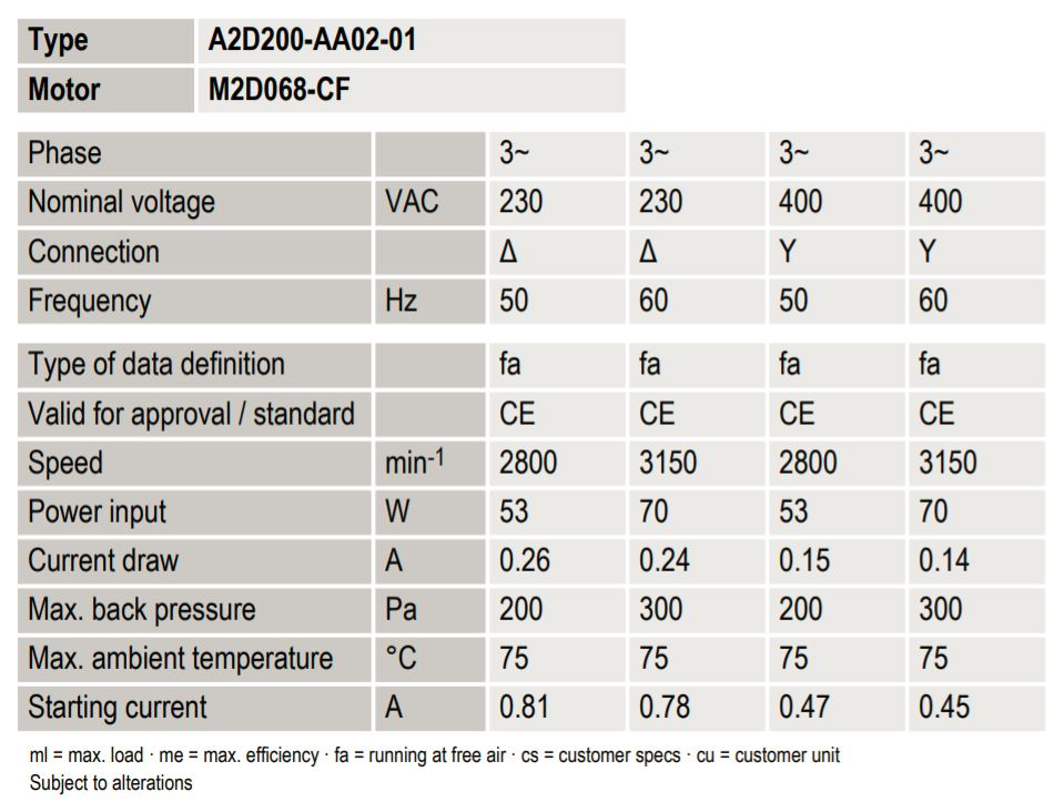
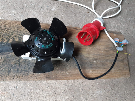
the Fan
AC axial fan A2D200-AA02-01 with permanent magnet synchronous motor M2D068-CF.

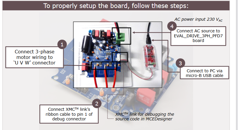
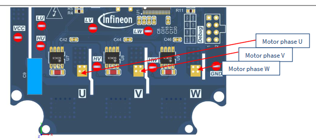
GUIDES
The best course book for this board is: EVAL_DRIVE_3PH_PFD7 Getting started guide.
and useful video: 'How to get started with iMOTION™ 2.0 | Infineon'
https://www.youtube.com/watch?v=MENV5en_ejE
unfortunately as you find in my next words, it wasn’t sufficient enough to conduct me to the successful end of roadtest.
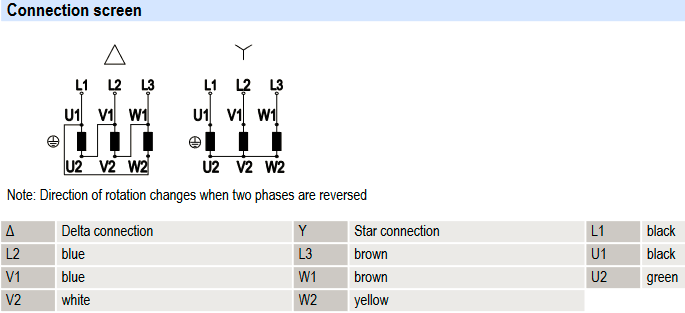
Some theory for understanding 3 phase network principles is required.
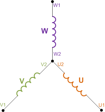
star delta
Delta for connecting to the inverter module
Star when conecting directly to 3X400 net
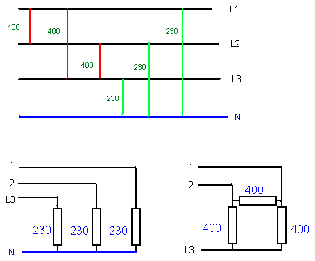
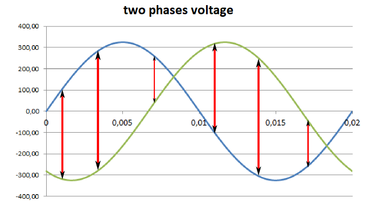
L2−L1=230V∗√2∗(sin(ωt+120)−sin(ωt))=230∗√2∗2∗sin(60)∗cos(ωt+60)=230∗√2∗√3∗cos(ωt+60)
α=ωt+120
β=ωt
ω=2∗Pi∗50Hz∗t
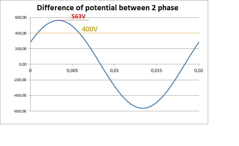
230∗√3≈398.37 [V]
maks. 230*1.73*1.41=561 [V]
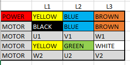
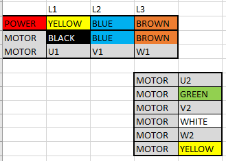
|
POWER |
YELLOW |
BLUE |
BROWN |
|
MOTOR |
BLACK |
BLUE |
BROWN |
|
MOTOR |
U1 |
V1 |
W1 |
|
MOTOR |
U2 |
V2 |
W2 |
|
MOTOR |
GREEN |
WHITE |
YELLOW |
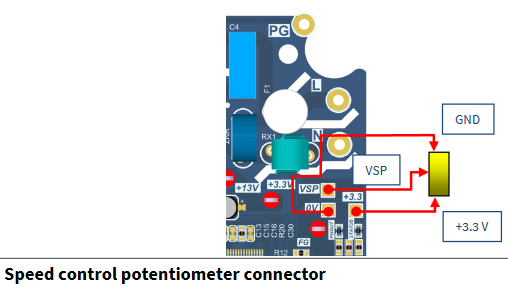
In manuals I found interesting option
Speed control potentiometer connector
unfortunately I was not able to employ that convenient solution
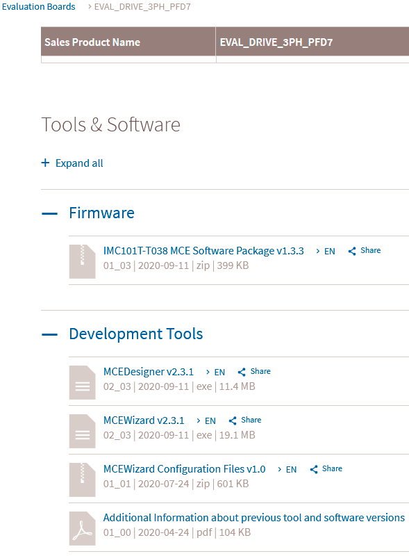
The next step was to prepare software environment
Downloads are available from the site: https://www.infineon.com/cms/en/product/evaluation-boards/eval_drive_3ph_pfd7/
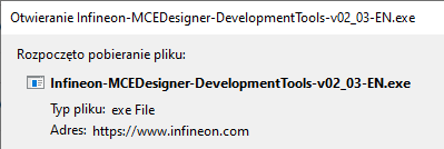
Software setup - download sequence
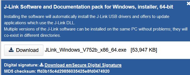
First I had to download drivers for the debugger - J-Link.
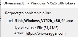
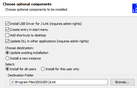
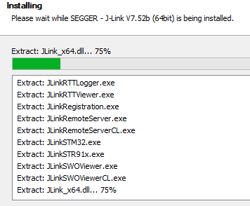
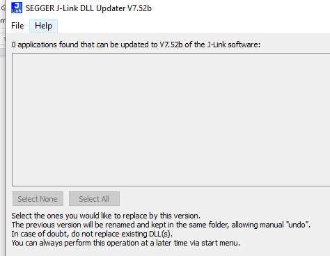
I decided to install the full package from Segger.
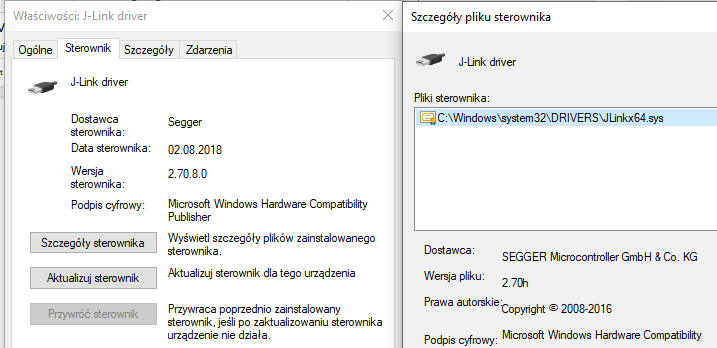
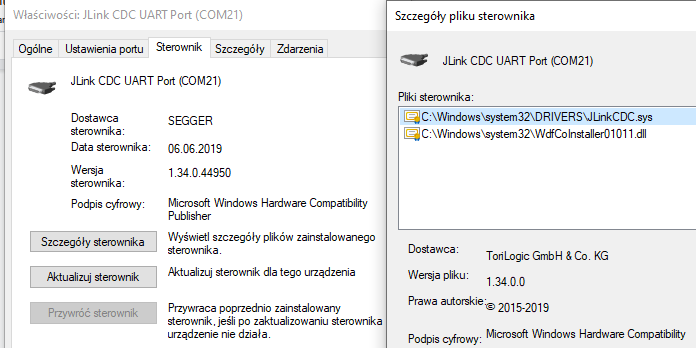
After inserting the debugger it was properly recognized and required drivers installed (WIN10)
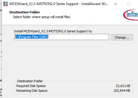
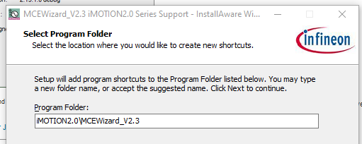
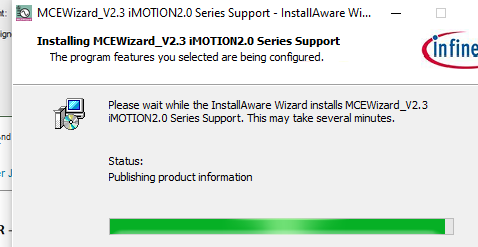
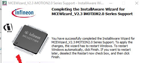
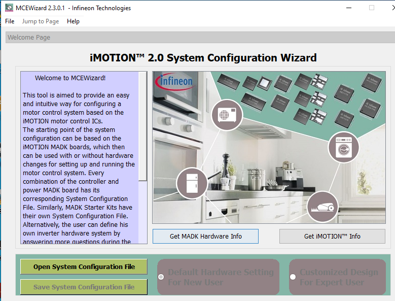
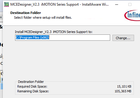
Installation and use of
MCEWizard (configure the parameter for the motor control.)
C:\Program Files (x86)\
iMOTION2.0\MCEWizard_V2.3
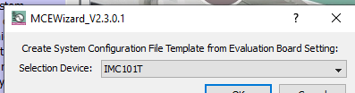
our device is IMC101T
Then I had to fill motor parameters step by step [questions]
some are simply available in datasheet AC axial fan A2D200-AA02-01
https://www.farnell.com/datasheets/2143382.pdf
Motor M2D068-CF02-07
https://pl.mouser.com/datasheet/2/120/Ebmpapst_06282016_M2D068CF0207-ENG-1165278.pdf
A2D200-AA02-01
nominal current= 260mA
and the first surprise ??? 4 or 2 ????
I tried both unfortunately without success...
Is that measure available indatasheet ?
in the theory - according to the papers of similar motors it is 150 or 17ohm
[...]
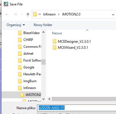
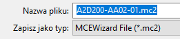
Now prepare the parameters file
A2D200-AA02-01.mc2
Now install and run:
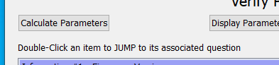
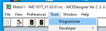
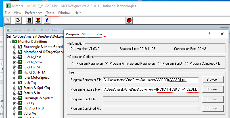
MCEDesigner (load the file generated in MCEWizard )
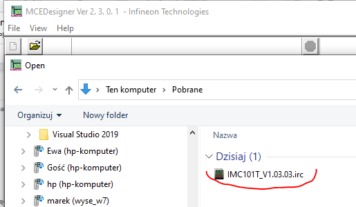
Run MCEDesigner, at the beginning open the configuration file.
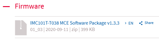
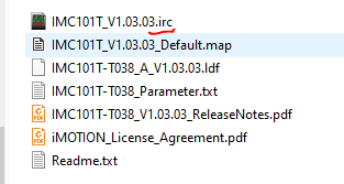
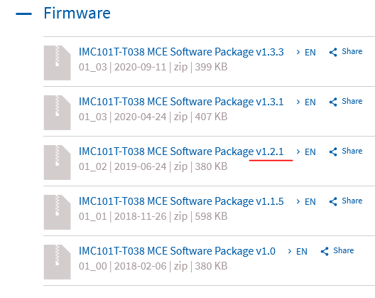
According to the guides and supporting video it should be in the nevest "firmware" file
IMC101T-T038 MCE Software Package v1.3.3
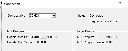
first surprise...
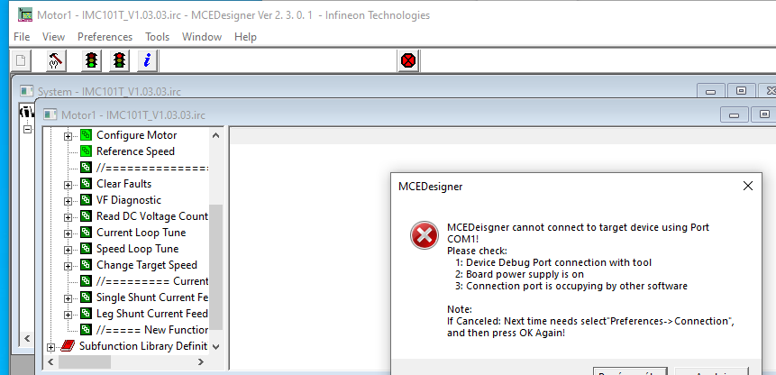
my fault I forget about setting the right COM
But unfortunately correction the communication port wasn't enough
These steps aren't described in guides and manuals. Unfortunately, from this point I encountered many difficulties with initial setup and run of the set.
The roadtest review was delayed and unfinished.
>>>>>>>>>>>>>>>>>>>>> look for IMC101T-T038 documentation <<<<<<<<<<<<<<<<<<<<<<
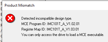
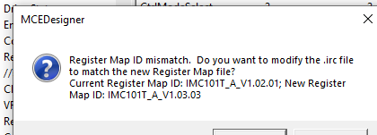
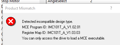
let's "downgrade"
still wrong!
as written in the message, only V1.02.01 is correct
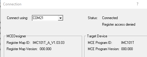
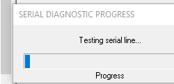
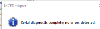
use available test of connection
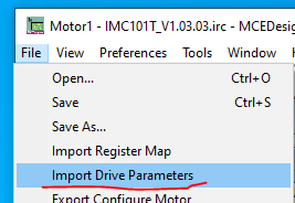
Now use MCEDesigner for program the controller
in the "FIRMWARE" file it is also .ldf file
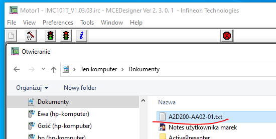
use the parameters txt file prepared before in MCEWizard
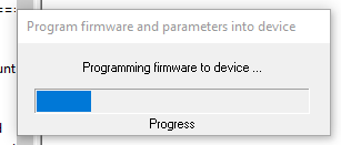
Now start
??????????????????? Festival of disappointments began ??????????????????????????????????????
The process froze, the MCEDesigner stopped responding, moreover blue LEDs on the inverter board went off
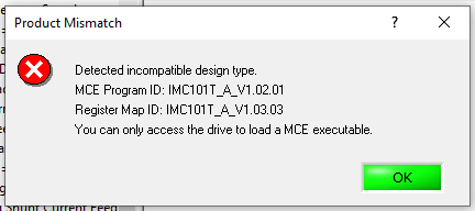
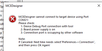
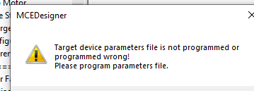
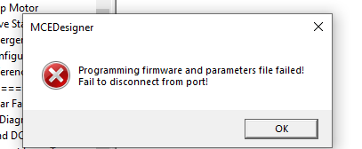
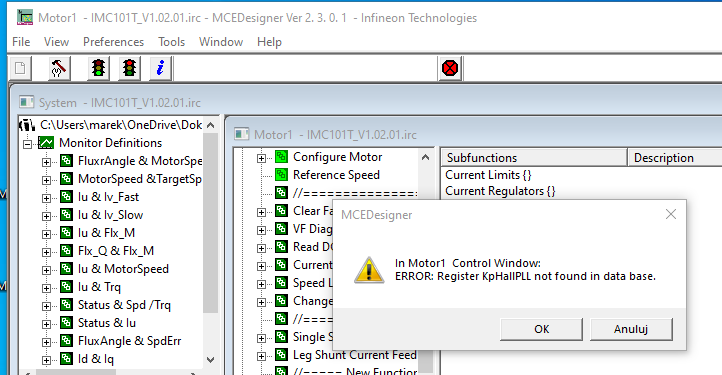
iritating messages apeared
or:
??????????? Did I brick the debuger or the inverter module or both... ?????????
And one notice!
In my opinion from the point of safety that is serious issue
without LEDs shining the board looks as unpowered...
>>>> BUT WE HAVE THERE 230AC onboard!!!
it may be truly dangerous!
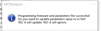
After some attempts unplugging, plugging again the set ...at last... programming went successful.
still some errors appear
????????? IMC101T_V1.03.03_Default.map??????????
I tried to load that file - just in case...
it was wrong way...
also that:
No documentation nor foras nor even infineon support helped and solved the issue.
The parameters file contains some errors or MCEDesigner can't use it properly.
I ended up with program parameters unable to start spinning the motor.
Only the soft noise and nearly imperceptible twitching
Regarding the MCEDesigner program and its powerful programming and visualization "laboratory"
indeed, I was able to see many parameters.
But the program looks unstable. Sometimes I was unable to run charts, sometimes it went good.
Finally I decided to check the motor run connecting it directly to mains.
Remembering from datasheet, that in my case only star connection is allowed.
LETS MOVE!
Instead of summary I decided to stop the report here
I still hope to get necessary information or konowledge to program the inverter properly and got the motor spinning and controlled.
My roadtest isn't finished!
Sorry if i disappointed someone by giving up now,
Marek