RoadTest: Quad-Channel, Analog Output Module
Author: Robert Peter Oakes
Creation date:
Evaluation Type: Semiconductors
Did you receive all parts the manufacturer stated would be included in the package?: True
What other parts do you consider comparable to this product?: The DAC is very specific to the Industrial market and the best way to compare would be to look at a complete design used to get the same thing, like a 16bit DAC and then a series of op amp and FET drivers to drive the industrial levels like 0-10V or 4-20mA I am not trying to say there are no comparable products but so far this one is the first I have come across with all the options built into it including dual power supply generation for each DAC channel
What were the biggest problems encountered?: there were a few problems that I dont regard as big, just a little speed bumps really. 1. wrong USB Cable 2. No easy way to discover the test software needed to exercise the board, this has to be able to run on windows and use the USB to SPI/I2C adapter provided with the board. 3. No "How to get something out of the DAC". There are many settings that need to be applied before any output is seen from the DAC, a few reviewers managed to get a change in output but only as a side effect, not the expected output. Once the right set of controls were set, everything worked great. It helps to read the technical documentation for the 8875 prior to giving up ans many clues are to be found in it regarding the settings needed, comparing this to the software allowed me to get it all working.
Detailed Review:
Intro and overview
1. Unboxing... It was in a nondescript brown box, now it is out... (Use your imagination it's way more interesting than seeing it for real  )
)
Included in the package
1, USB Lead, no good for the review but nice to have a good spare. 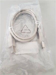
2. The SM-USB-DIG USB to I2C/SPI adapter 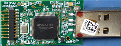
3. The DAC8775EVM module (Not available for sale to joe public!) 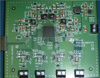
Once you find the software (Link for convenience) that is actually designed for the purchasable version of the board, you can start to get up and running
this is the purchasable version of the board:- , link to buy:- By this board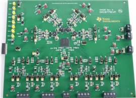
So here is where my first video comes in... enjoy
Technical Stuff
As the board we have for review is not available for purchase by the public, I think my approach is to focus on the chip rather than the board, the DAC8775 is a rather awesome chip in that is not only has a quad channel 16bit DAC than has a large number of output configurations including current and voltage, but it also includes the necessary Buck / Boost converters to simplify your design and BOM, these provide both positive and negative supply rails for each of the channels and will dynamically adjust their output in order to minimize the power consumption of the overall solution
Here are some pertinent specifications
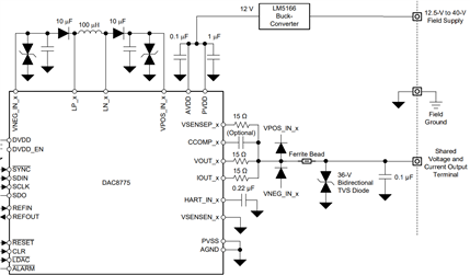
Here is an overview of the chip
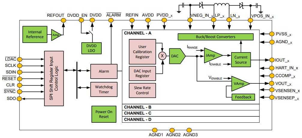
As you can see, a very simple computer side interface, there are only a simple set of registers for programming and some of those are shadowed based on DAC number so there at the same address but require the coder to set the target register before writing o it, this includes the DAC Data, Calibration, BUCK/Boost and output options. The full data sheet can be found here http://www.ti.com/lit/ds/symlink/dac8775.pdf
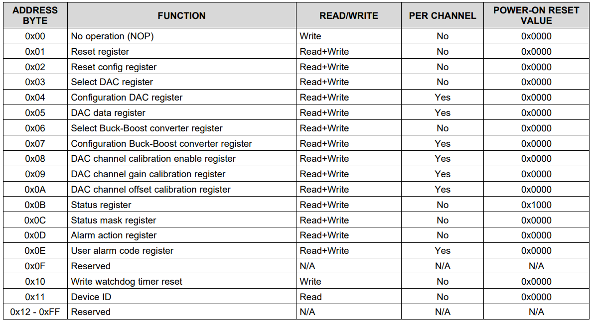
Table of registers for the DAC8775
A few observations from the PDF
Simple and effective Current output using a differential OP-AMP pair and MOSFETS, each with their own current sense resistors
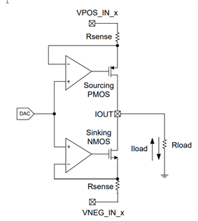
The voltage stage is of course different but equally simple
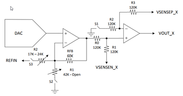
The nice thing about the evaluation board is how they have configured both current and voltage outputs to the same header and does not require jumpers to switch between current or volts, just re-configure the 8775 chip
Time for another video I think
OK, so enough of the technical details, if you want to know more, go look at the PDF documents here http://www.ti.com/lit/ds/symlink/dac8775.pdf and here http://www.ti.com/lit/ug/tiducv5/tiducv5.pdf
The Software
The software is a single standalone package (DAC8775EVM.ZIP) downloadable from TI here:- DAC8775EVM DAC8775 Evaluation Module | TI.com , you may need to register but you can get it.
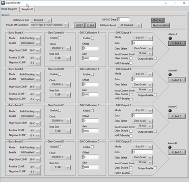
Once it is downloaded and installed run the program and you should see this
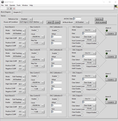
As you can see, the UI is not designed to provide dynamic testing but to simply replicate all the registers in an easy to use UI, providing all the options but no requirement to understand how to use SPI or even what the hardware is. it is just plug and play...... sortof.
Plug in the SM-USB-DIG adapter to the DAC8775EVM board, be careful of the pins, there very fine and only 1mm spaced, then plug the ESB extender into the SM-USB-DIG module and to your computer, apply 12-40V to the DAC module and you're ready to rock...
Now referring to the image below, you need to set up a few things
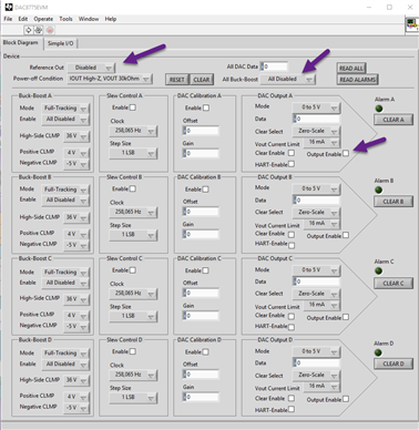
1. Turn on the voltage reference, this board is different from the one you can buy in that it does not use an external reference chip.
2. Using the "All Buck-Boost control", select "All Enabled", this is easier than doing each individual one in the left column.
3. Enable the outputs of the required DACs
4. press the RESET button
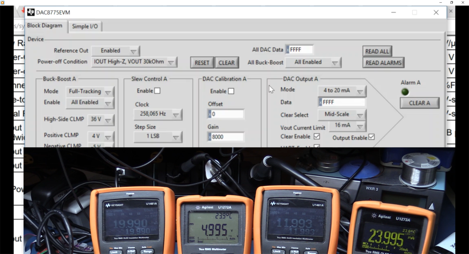
Your UI should now look like this, note that the calibration Gain registers have changed to 0x8000, this reflects a 2's complement value meaning no gain adjustment is applied (Default value)
You should now be able to set output values and change output modes as you desire... time for the last video
As you will see from the video, the chip performs easily to specification and beyond, you can set all of the modes with ease and so long as you remember to switch your DMM from volts to current, you will get out the values you expect. You will see in the video that I demonstrate Slew Rate control, yes this could be done in software but of its there, why not use it if needed, you can actually slow down the rate of change of the outputs quite considerably.
As for Alarms, I also show in the video several of the alarm nodes working very successfully, bot in current and in voltage modes.
Example of multiple output modes at the same time and how accurate they are, 0-20mA, 0-5V, 0-12V and +-24mA (All full scale unadjusted with the calibration registers)
In summary
I found the board to be very capable and does allow the user to test out the "Static" capabilities of the DAC8775 chip. out of the gate it is accurate and easy to evaluate. I would say that some improvements to the software would be welcome or at least a better guide to its use, but given that this board is not for sale, its tough to complain and if you look where the alternate evaluation board for the DAC8775 chip, the software and descriptions do match up. This board is way simpler than the released version though, there are no jumpers to get wrong but then there are also no test points provided. If you want to evaluate this chip then you will need to buy the alternate board. it is about 200$ though, considering the chip itself is 17$ in quantity, 30$ for a one off, this board should be a little cheaper and if so probably would be adopted more by end users looking for an all in one solution
Aside from the cost of the available board, the chip itself is ideal for Industrial Control applications, in that it covers all the standard analog scenarios (0-10V and 4-20mA being the primary), it has a very low BOM and is very similar to other DACs I have reviewed in the past from TI (This makes it easier to figure out the programming and interfacing). The single channel version is not so lucky as it does not include the buck boost converters etc, it would have been nice to have a complete solution like this in a single channel version as well... ah well 
As soon as i get a chance I will look at using an Arduino or launchpad to exercise the board, until then I hope you found this review useful and informative.
Links:
Eval module as tested TIPD215 Less Than 1-W, Quad-Channel, Analog Output Module With Adaptive Power Management Reference Design | TI.com
Ref Design 1 http://www.ti.com/lit/ug/tiducv5/tiducv5.pdf
Ref Design 2 http://www.ti.com/lit/ug/tiducv6/tiducv6.pdf
User Guide http://www.ti.com/lit/ug/sbau248/sbau248.pdf
DAC8775 Data sheet http://www.ti.com/lit/ds/symlink/dac8775.pdf
Purchasable Eval Module and Software DAC8775EVM DAC8775 Evaluation Module | TI.com
Required USB-SPI adapter http://www.ti.com/lit/ug/sbou098/sbou098.pdf


Top Comments
I bow to your superior skills and perseverance.
You did an excellent review and highlighted the features of the board that got me excited about testing it, but I was not able to follow all of the clues…
Robert Peter Oakes, if you have time and tools, it would be great if you could record a working SPI sequence to get an output voltage set via the GUI.
I'm trying to do it using the explanations in the…
Not needed, Robert Peter Oakes. I got it working.