RoadTest: Enroll to Review the ADI Bluetooth®︎ 5 MCU Board with a 6-axis accel/gyro
Author: parthsanepara
Creation date:
Evaluation Type: Development Boards & Tools
Did you receive all parts the manufacturer stated would be included in the package?: True
What other parts do you consider comparable to this product?: nordic - nrf52 , nrf53 series MCUs
What were the biggest problems encountered?: Na
Detailed Review:
Thank you for selecting me for this RoadTest. I apologize for missing the initial timeline for this review. I will do my best to thoroughly review the Maxim Integrated MAX32666FTHR Low Power BLE ARM Cortex-M4 MCU kit.
Unboxing
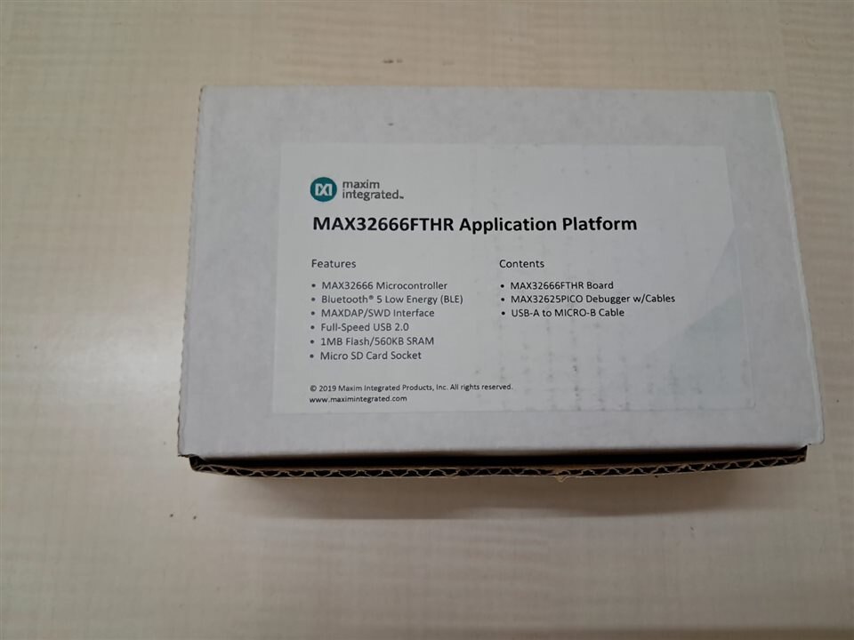
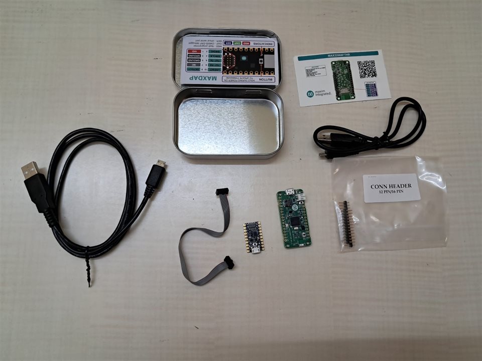
I received the courier on time. The items were securely packaged in a standard Maxim Integrated box. The list of received items is provided below:
| {gallery}Unboxing |
|---|
|
IMAGE TITLE: MAX32666FTHR Application platform Box |
|
IMAGE TITLE: Device + Cable |
Hardware Setup: need to solder the Header Pin in the FTHR board.
Getting Started
Overview of MAX32666FTHR Kit – DataSheet - https://www.analog.com/media/en/technical-documentation/data-sheets/MAX32666FTHR.pdf
Features

MAX32666FTHR Pinout Diagram
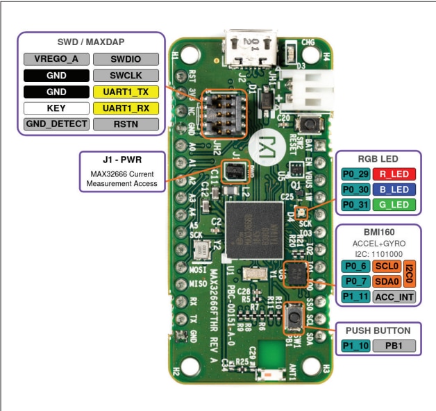
Top View – Debugger Header Pinout | RGB Light Pin Config | Push Button Pin | BMI160 (6 Axis IMU ) I2C Pinout | Current measurement jumper
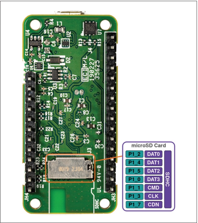
Bottom View: MicroSD Card Pin config
Windows Development SDK Setup:
To begin development with the FTHR board, please refer to the relevant page for detailed instructions and guidance. It is important to read through this material to ensure a smooth setup and development process.https://www.analog.com/en/resources/evaluation-hardware-and-software/evaluation-boards-kits/max32666fthr.html#eb-overview
Download SKD installation file Link - https://www.analog.com/en/resources/evaluation-hardware-and-software/software/software-download.html?swpart=SFW0010820B#
Download: MaximMicrosSDK_win.exe required analog account login for download.
SDK Installation Process:
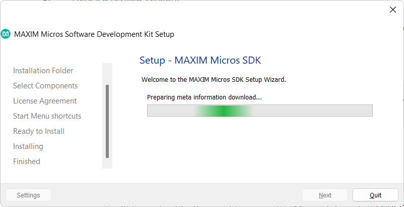
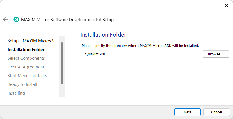
To begin the SDK installation, follow the steps outlined below. During the installation process, you may be prompted to provide some information, similar to the requirements of a typical application installation. On my Windows 11 PC, the entire installation took approximately 20 minutes.
Installation Steps:
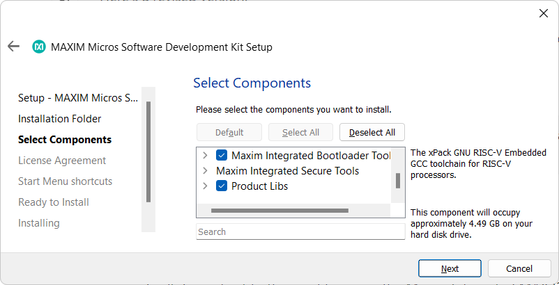
This SDK installation process includes the Eclipse-based IDE, with all relevant plugins and the SDK toolchain pre-configured. While there are also VS Code-based plugins available, I chose to proceed with the Eclipse-based IDE setup, as it aligns with my preferences.
| {gallery}SDK Setup |
|---|
|
IMAGE TITLE: Setup |
|
IMAGE TITLE: SDK Installation Path set |
|
IMAGE TITLE: Select Component |
|
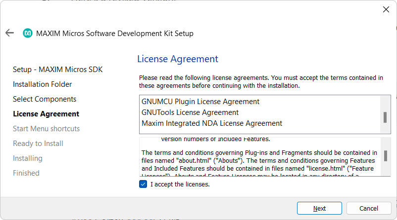
IMAGE TITLE: License Agreement |
|
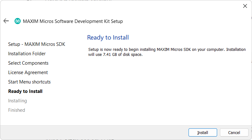
IMAGE TITLE: Installation |
|
IMAGE TITLE: Progress |
|
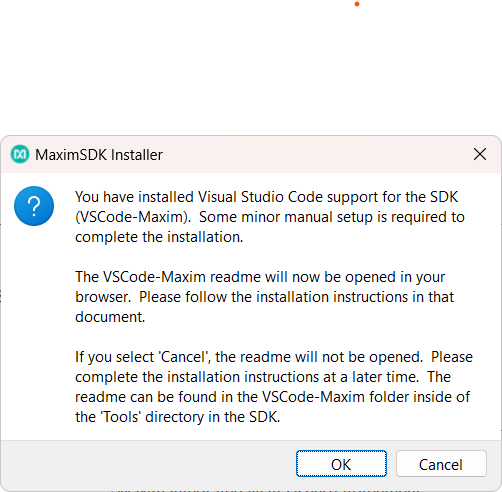
IMAGE TITLE: VS Code Plugins setup window |
After the installation is completed, navigate to the installation directory and run setenv.bat. This script will configure the global environment settings.
The setup folder for MaximSDK is organized as follows:
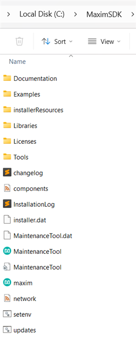
To open Eclipse, navigate to C:\MaximSDK\Tools\Eclipse\cdt and run eclipse.exe. You may be prompted to specify a workspace path on the first launch. Choose a convenient location for the workspace and open the Eclipse window.
Eclipse first launch window looks like below:

First Example Code (Hello world)
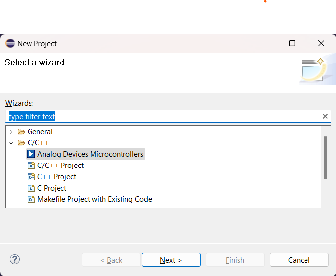
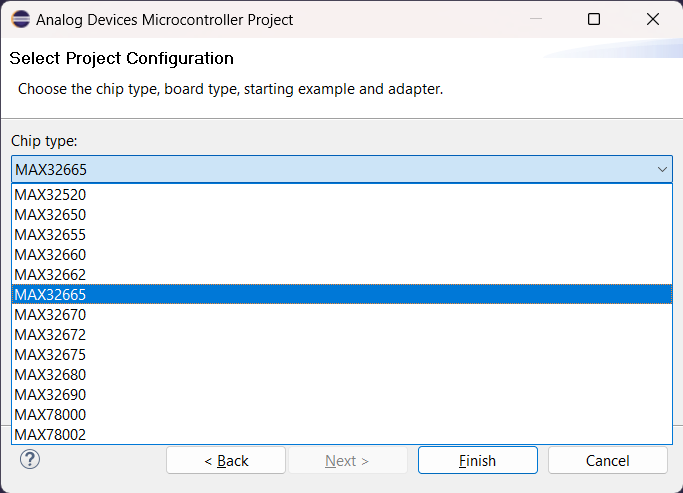
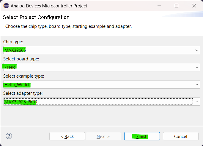
To create your first project and print Hello_World in the debug window, follow these steps:
| {gallery}Hellow_world Project create |
|---|
|
IMAGE TITLE: Select Analog Device MCU |
|
IMAGE TITLE: Select MAX32665 |
|
IMAGE TITLE: Set project parameter -> Finish |
Step 1: Create a New Project
Step 2: Configure Project Settings
Step 3: Select Device and Configuration
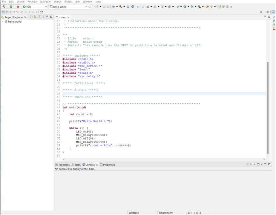
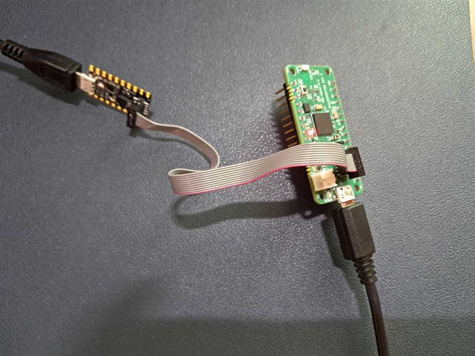
Eclipse IDE created a 'Hello World' project that looks like below. The project was built and executed using the standard Eclipse build process, and the HEX file was flashed onto the FTHR Kit.
| {gallery}Hello World Example |
|---|
|
IMAGE TITLE: Eclipse View |
|
IMAGE TITLE: FTHR Kit and Debugger Connection with PC |
Result :
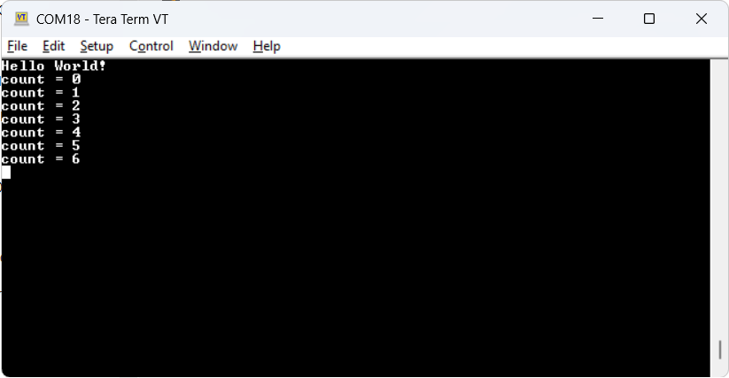
Open any serial terminal :I used TeraTerm and connected to the Detected COM port. Set the baud rate to 115200. In the terminal, you will see the output as shown below: the message 'Hello World!' is printed, and incrementing count = 1 ++. Additionally, the LED 0 (red LED) on the FTHR Kit blinks according to the programmed logic.
BLE Peripheral Example
create a New Project as mentioned process in the Hello World Project. and in the final step select the example code as BLE_Periph in the example dropdown. and build project and Flash.
Serial Terminal Output
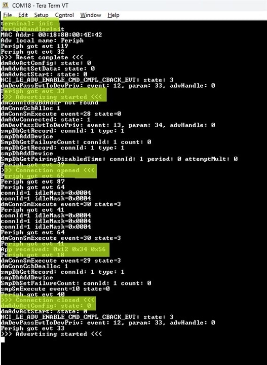
I have highlighted the following event logs: 1) Advertisement started, 2) Connection established, 3) Data sent from mobile to device (e.g., 0x123456), 4) Device disconnected, and 5) Upon disconnection, advertisement restarted and reconnection initiated.
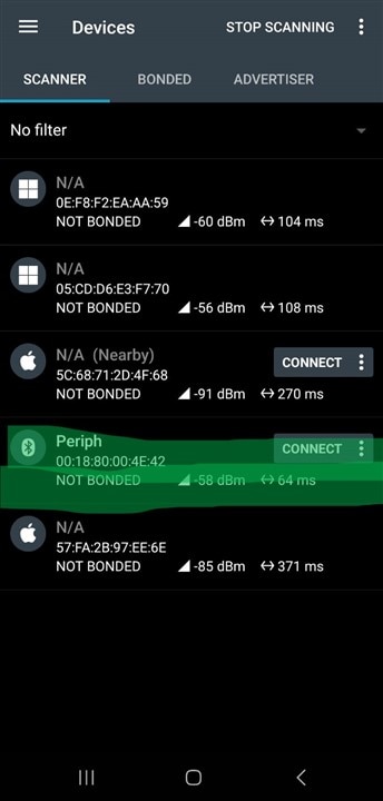
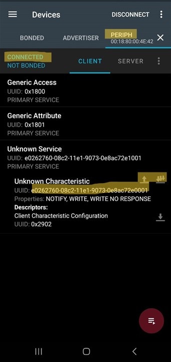
For the BLE test, I used the NRF Connect Android application to conduct a connectivity test and send data via the GATT Custom profile.
| {gallery}My Gallery Title |
|---|
|
IMAGE TITLE: nRF Connect App - BLE Advertise List |
|
IMAGE TITLE: Connected Device Service List |
In this BLE test, I intended to measure power consumption using the PPK2 kit, but I don't have the correct battery connector that is compatible with the FTHR Kit. (Supposed to provide Battery connector with this kit).
Conclusion
in conclusion, MAX32666 MCU offers a robust feature set, including Bluetooth Low Energy (BLE) support and low power consumption, making it an excellent choice for a variety of applications. It is particularly well-suited for use in wearable devices, home automation systems, HVAC systems, and other applications that demand efficient power management and reliable BLE connectivity.
From a development perspective, the setup process is straightforward and user-friendly, even for beginners working with BLE MCUs. Additionally, the MCU's compatibility with Zephyr RTOS is a significant advantage, and I intend to explore this further by setting up Zephyr RTOS in future.