Quick and easy way to Edge AI with PSoC 62S2 AI kits

View table of contents ...  

RoadTest: Become a Tester of the PSOC™ 6 AI Evaluation Kit enabled with DEEPCRAFT™ AI/ML software solutions

Author: fyaocn

Creation date:

Evaluation Type: Development Boards & Tools

Did you receive all parts the manufacturer stated would be included in the package?: True

What other parts do you consider comparable to this product?: STM32Nxxx DK

What were the biggest problems encountered?: NA

Detailed Review:

1 Introduction

The Infineon PSoCM6 AI Kit offers a range of capabilities for users interested in artificial intelligence (AI) and embedded system development. It provides a platform to build, optimize, and validate models, as well as develop embedded products using Infineon Microcontrollers (MCUs).
Model Development and Product Creation
Users can either build their own models or purchase ready - made models. The kit allows for model optimization and validation, which is crucial for ensuring the accuracy and performance of AI models. After the model is ready, it can be integrated into embedded products developed with Infineon MCUs.
Development Tools
Tools like Modus Toolbox and DeepCraft studio are available for the development process. These tools support various aspects of the development cycle, from data acquisition to model deployment.
Software Components
 The PSoCM6 AI Kit has a variety of software components. It includes data collection and Wi - Fi/HTTP client - server deployment capabilities. There are also peripheral drivers and manufacturing tools. Additionally, ready models are provided, and it supports TensorFlow Lite Micro, which is a lightweight version of TensorFlow designed for microcontrollers. It offers multiple connectivity options such as MQTT, HTTP, and Wi - Fi. Secure sockets are also available, ensuring secure communication. The kit also supports emUSB, AIROC, and Mbed LwIP for different types of connections. It can handle various types of data related to different applications like cough, snore, siren, and baby cry detection.
Sensors and Peripherals
The kit is compatible with various sensors and peripherals. Although specific details about them are not fully elaborated in the given content, they play a crucial role in data collection for AI applications.
In summary, the Infineon PSoCM6 AI Kit is a comprehensive platform that combines model development, connectivity, acceleration, and application - specific features to enable users to create advanced AI - powered embedded products.

2 Technical Spec

2.1 PSoC 62S2 AI kits

Here is the front and back view of this small size kits

comes with  rich functions by parts and components,
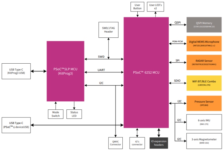
 2.1.1 PSOCTm 6 MCU

  • Parameters
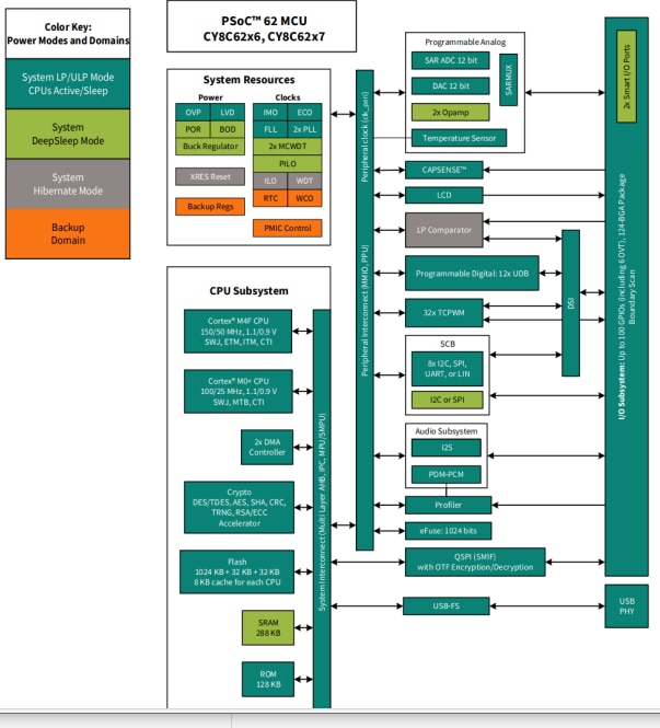
    • Dual CPU Subsystem: Comprises a 150 MHz Arm® Cortex® - M4F and a 100 - MHz Cortex - M0+ CPU, enabling efficient parallel processing.
    • Memory: Features 2048 KB application flash, 32 KB auxiliary flash, 32 KB supervisory flash, and 1024 KB SRAM for data and code storage.
    • Power Supply: Operates at 1.7 V to 3.6 V, with a Deep Sleep mode current of 7 µA, suitable for battery - powered applications.
    • Clocking: Offers a range of clocking options. It has a 24 MHz crystal (Y2) for high - performance clock generation (ECO mode) and a 32.768 KHz crystal (Y1) for low - power operation (WCO mode).
    • Communication Interfaces: Supports Quad - SPI (QSPI)/Serial Memory Interface (SMIF) for high - speed data access with XIP, encryption/decryption, and a 4 KB cache. Also includes serial communication interfaces like configurable SCBs, USB full - speed device interface, and SD Host Controller/eMMC/SD controllers.
    • Analog Processing: Incorporates a 12 - bit 2 - Msps SAR ADC and low - power comparators for system's Deep Sleep and Hibernate modes.
    • GPIOs: Provides 102 programmable GPIOs with smart I/O ports for Boolean operations and customizable drive modes, strengths, and slew rates.
  • Structure
    • Power Supply: The core power supply connects to the VCC_3V3 rail, while the IO power supply connects to both VCC_3V3 and VCC_1V8 rails. Ferrite beads isolate digital and analog domains, and decoupling capacitors filter high - frequency noise.
    • IO Ports: It has 15 IO ports, each associated with a dedicated power supply. Different ports can be configured for various functions, and their logic levels vary depending on the power rail they are connected to.
    • Clock Sources: The 24 MHz crystal (Y2) is connected to P12[6] and P12[7], and the 32.768 KHz crystal (Y1) is connected to P0[0] and P0[1]. For USB functionality, an external clock source is recommended.
    • External Programming/Debugging: A 10 - pin header (J4) is available for external programming/debugging using tools like MiniProg4, in addition to the onboard KitProg3.
    • USB Device: The PSOCTm 6 MCU has a Type - C USB (J2) which can be used as a power source and for USB communication. The USB lines are connected to the MCU through ESD protection (U9).

2.1.2. KitProg3 Programmer and DebuggerParameters

    • Based on PSOCTm 5LP: Utilizes the CY8C5868LTI - LP039 PSOCTm 5LP device.
    • Modes: Operates in CMSIS - DAP Bulk mode (default) or CMSIS - DAP HID mode. Programming is faster in Bulk mode.
    • Voltage Measurement: Can measure the onboard target voltage through an ADC and a voltage divider circuit.
  • Structure
    • Connection: Connects to the USB port of a PC through a Type - C USB connector (J1) and to the SWD and other communication interfaces of the PSOCTm 6 MCU.
    • Serial Interface: Functions as a USB - UART and USB - I2C bridge. Its USB - Serial pins are hard - wired to the I2C/UART pins of the PSOCTm 6 MCU, and the I2C pins are also available on the expansion I/O header.
    • Mode Selection: A mode selection button (SW3) connected to the P1[2] pin of the PSOCTm 5LP device is used to switch between programming modes, and a status LED (D12) connected to P1[4] indicates the programming status.

2.1.3. Power Supply System

  • Parameters
    • Input Sources: Can be powered by 5 V from onboard KitProg3 Type - C USB connector (J1), 5 V from the PSOCTm 6 MCU Type - C USB connector (J2), or 3.6 V - 4.2 V from the Li - ion battery input connector (J3).
    • Output Voltages: Provides 3.3 V (core and I/O), 1.8 V (I/O), and 2.7 V - 4.2 V (VBAT) for the PSOCTm 6 MCU and 5 V for KitProg3 operation.
    • Current Limitations: The 5 V/3 A output from J1 or J2 is limited to 1A by the power path controller U8 and the host power rating capability. The battery's maximum charging current is 190 mA.
  • Structure
    • Power Input: The supply rails KP_VBUS (5 V from J1) and P6_VBUS (5 V from J2) are combined into VBUS_IN through ‘OR’ing diodes (D5, D6). VBUS_IN serves as an input to the power pathway with a Li - Ion battery charger (U8).
    • Voltage Regulators: There are three voltage regulators on the board: a 3.6 V buck - boost regulator (U11) for the Wi - Fi & Bluetooth® module VBAT power supply, a 3.3 V LDO linear voltage regulator (U20) for the PSOCTm 6 MCU (core and IO domain) and onboard peripherals, and a 1.8 V LDO linear voltage regulator (U21) for the PSOCTm 6 MCU (IO domain) and onboard peripherals.

2.1.4. Sensors

  • XENSIVTm Digital Barometric Pressure Sensor (DPS368XTSA1)
    • Parameters: Uses an I2C interface for communication with a default secondary address of 0x77 (can be changed to 0x76 by populating R66). It has an interrupt signal, PSEN_INT_P1_4.
    • Structure: Connects to the PSOCTm 6 MCU through I2C_SCL_P0_2 and I2C_SDA_P0_3 pins.
  • XENSIVTm MEMS Digital Microphones (IM72D128V01XTMA1)
    • Parameters: Two microphones share the same PDM bus. The left microphone's data is available on the falling edge of the PDM_CLK (SELECT pin tied to GND), and the right microphone's data is available on the rising edge (SELECT pin tied to VCC_3V3). They are supplied from a 3.3 V rail.
    • Structure: Each microphone has a SELECT pin, and they are connected to the PSOCTm 6 MCU through PDM_CLK_P10_4 and PDM_DATA_P10_5 pins.
  • XENSIVTm 60 GHz RADAR Sensor (BGT60TR13CE6327XUMA1)
    • Parameters: A 60 GHz radar sensor with integrated antennas (one transmitting and three receiving). It uses an SPI interface for communication, along with an interrupt signal (RSPI_IRQ_P11_0) and reset signal (RXRES_L_P11_1). It requires an 80 MHz clock input from an onboard crystal oscillator (U15).
    • Structure: Connects to the PSOCTm 6 MCU through SPI - related pins (RSPI_CS_P12_3, RSPI_CLK_P12_2, RSPI_MOSI_P12_0, RSPI_MISO_P12_1) and uses power supply filters, including ferrite beads and capacitors.
  • 6 - axis IMU (BMI270)
    • Parameters: Provides 3 - axis acceleration and 3 - axis gyroscopic angular rate data. It uses an I2C interface for communication with a default secondary address of 0x68 (configurable to 0x69). It has two interrupt signals connected to the PSOCTm 6 MCU.
    • Structure: Connects to the PSOCTm 6 MCU through I2C_SCL_P0_2 and I2C_SDA_P0_3 pins.
  • 3 - axis Magnetometer (BMM350)
    • Parameters: Senses the direction and strength of the geomagnetic field. It uses an I2C interface for communication with a default secondary address of 0x15 and has an interrupt signal MAG_INT_P1_0.
    • Structure: Connects to the PSOCTm 6 MCU through I2C_SCL_P0_2, I2C_SDA_P0_3, and MAG_INT_P1_0 pins.

2.1.5. Wi - Fi + Bluetooth® Module 

  • Parameters
    • Wireless Capabilities: Offers 802.11b/g/n Wi - Fi and Bluetooth® 5.2 capabilities.
    • Power Supply: Powered by an external VBAT supply voltage of 3.6 V and an IO's supply voltage of 1.8 V for interface IOs.
    • Interface: Communicates with the PSOCTm 6 device using a standard SDIO interface for WLAN and UART interface for Bluetooth® operation.
  • Structure
    • Power Supply: The VBAT and VIO power supplies are provided through an external source. An onboard oscillator (Y3) of 32.768 KHz provides an external sleep clock input (LPO_IN) to the module.
    • Interface Signals: Connects to the PSOCTm 6 MCU through multiple pins such as BT_REG_ON, WL_REG_ON, WL_HOST_WAKE, BT_HOST_WAKE, etc., which control power - up/down and communication functions. The antenna output is connected to an onboard chip antenna with a matching circuit.

2.1.6. Expansion Headers

  • Expansion Headers (J17, J18, J15)
    • Parameters: J17 and J18 are 100 mil pitch expansion headers, and J15 is a low - profile connector. They provide connectivity to some of the PSOCTm 6 MCU GPIOs.
    • Structure: J17 and J18 have specific pin assignments for various GPIOs, and J15 has pins connected to PSOCTm 6 MCU GPIOs and SDHC - related signals. By default, J17 and J18 are not populated.
  • I2C Interface Connector (J16)
    • Parameters: A 4 - pin connector compatible with QWIIC connection system boards. It extends the I2C interface from the PSOCTm 6 MCU.
    • Structure: Connects to the PSOCTm 6 MCU through I2C_SDA_P0_3 and I2C_SCL_P0_2 pins, allowing attachment of QWIIC - compatible add - on boards.

3 Data streaming and Training

3.1 Update firmwares

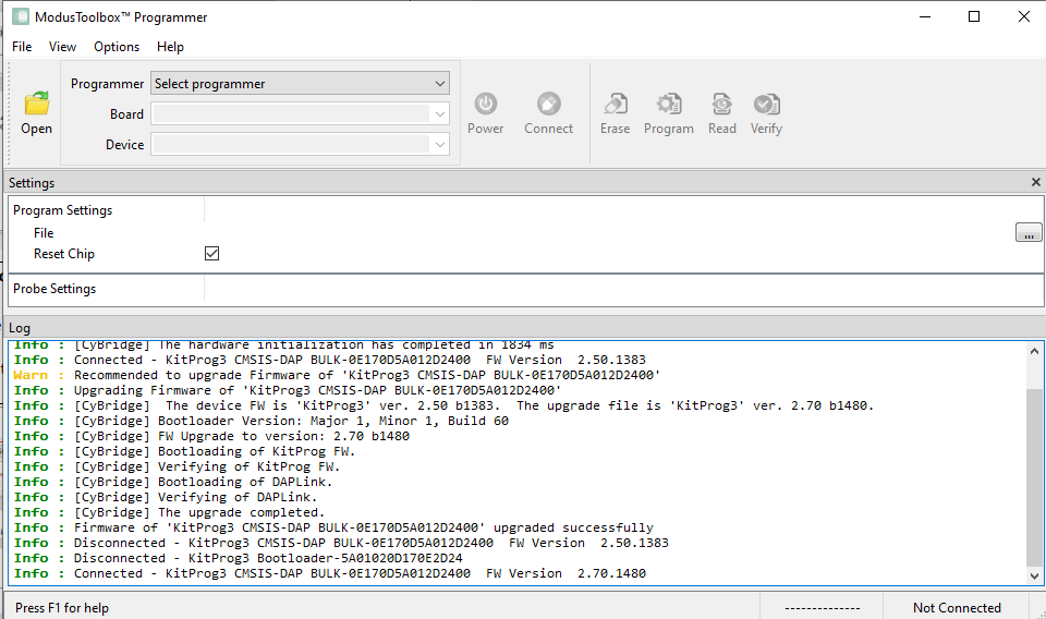
Install and connect the  PSoC 62S2 AI kits, but the board can not be detected, since the firmware shall be updated first
Install Modus toolbox programmer, the kitProg3 driver can be update, it does not matter if continues.
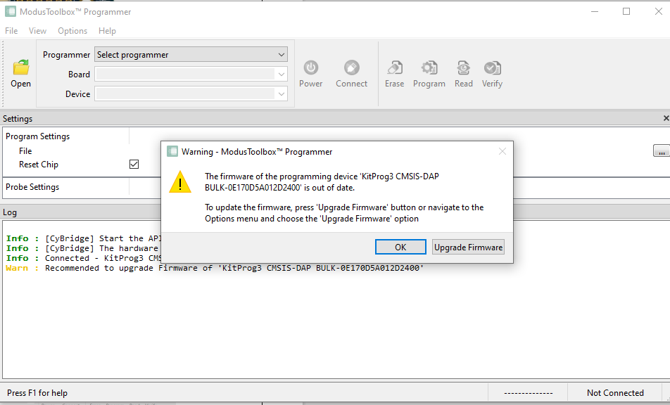
Update the firmware for KitProg3 first
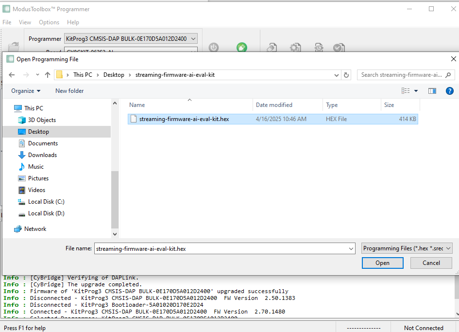
the download the data stream firmware 
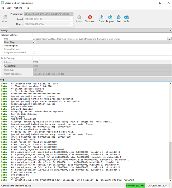
connect the board and program it
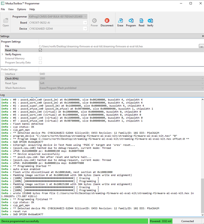
until it is successful.
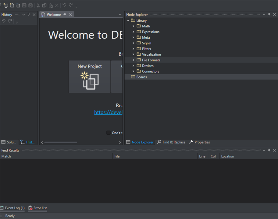
3.2 Data streaming with Deepcraft Studio

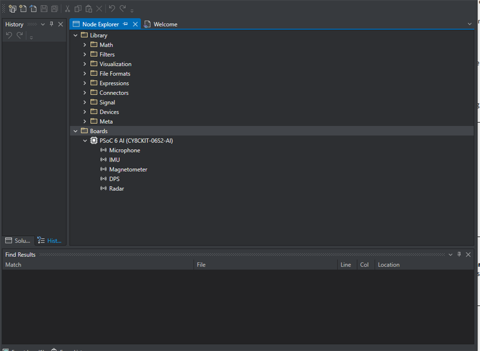
Now the board is shown, and available sensor, since the data is exchange according to protocol 2 instead of protocol 1 
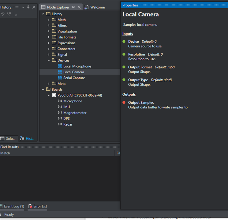
local camera is camera on PC, it is available for data streaming as well,
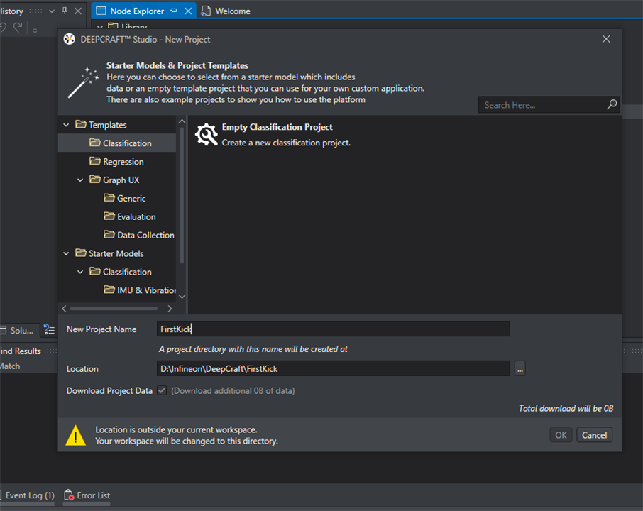
Create on UX project
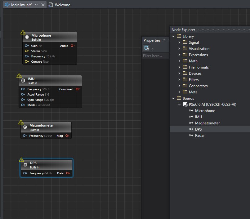
drag the sensor to left panels
add data tracks
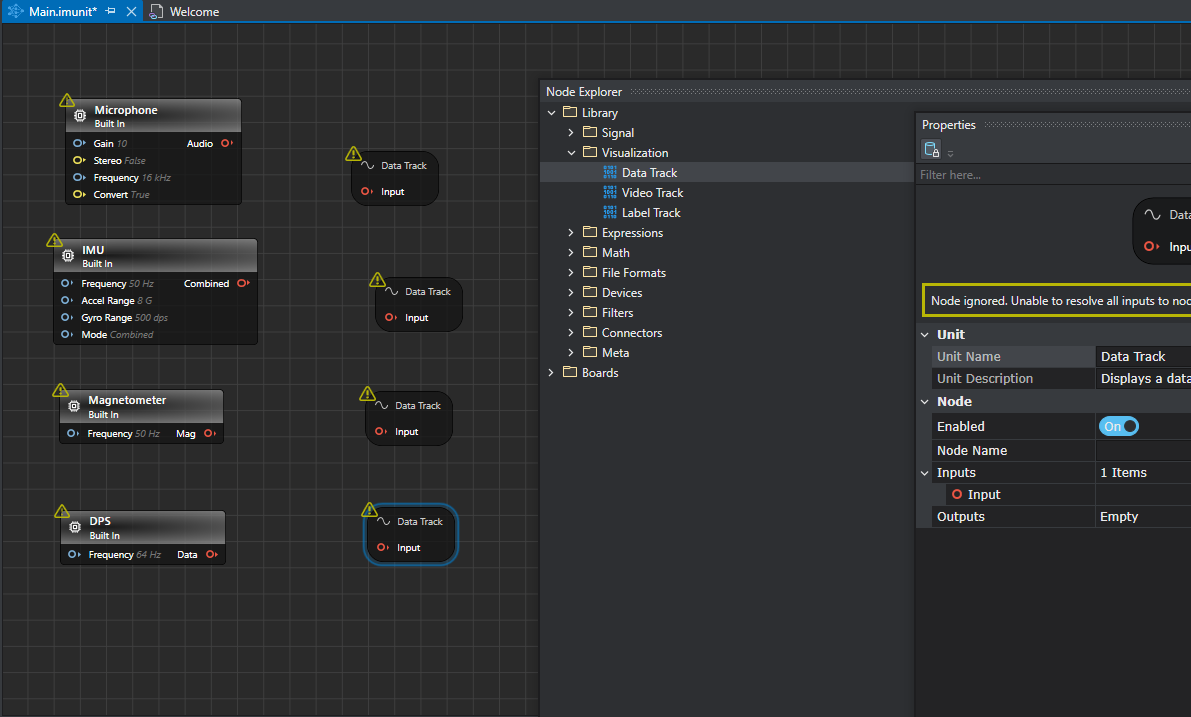
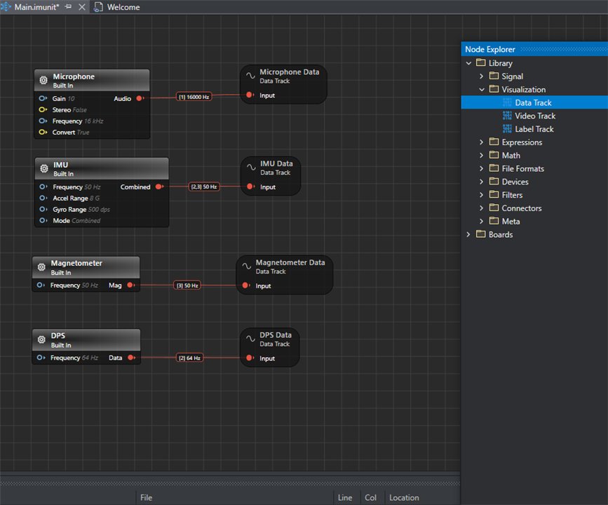
and connected them
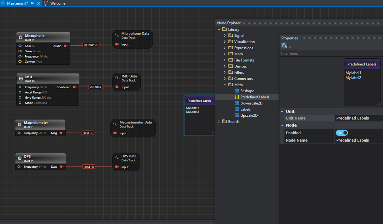
add preset label , this is used in training and labeling.
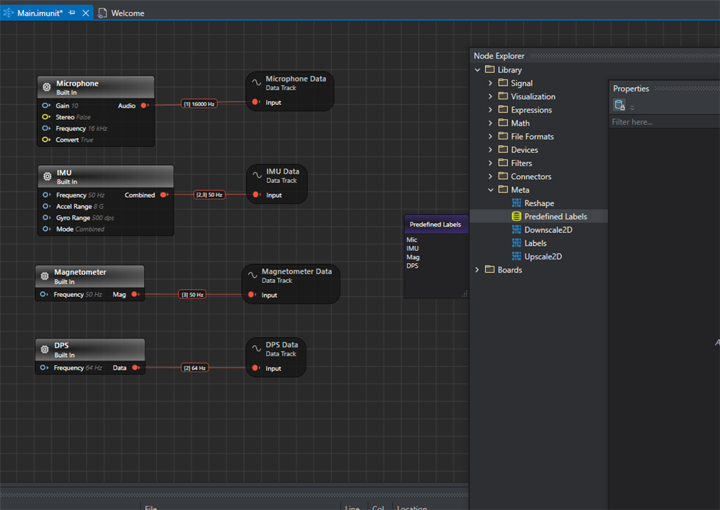
change the label as you like, this is for label the data blocks,
once completed, start on live session , the sensors in different track show how data streaming
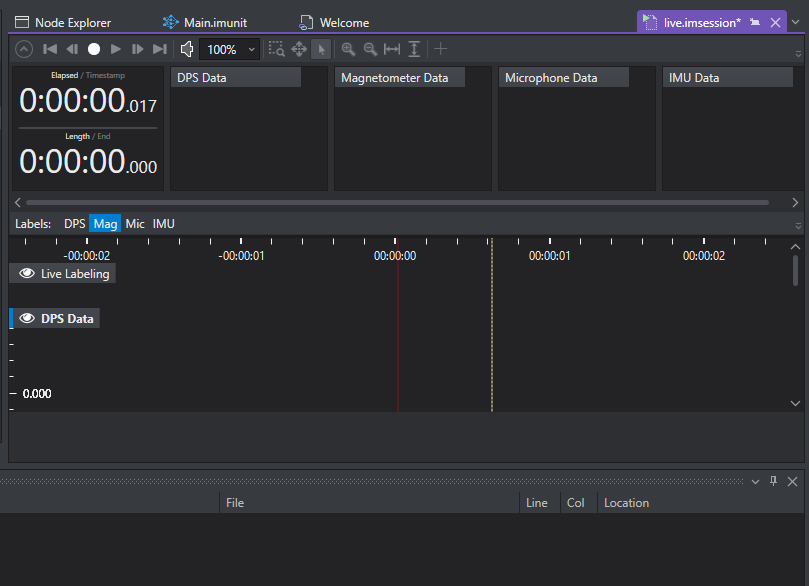
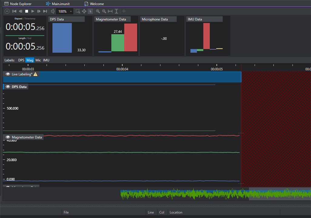
start recording, the data is coming
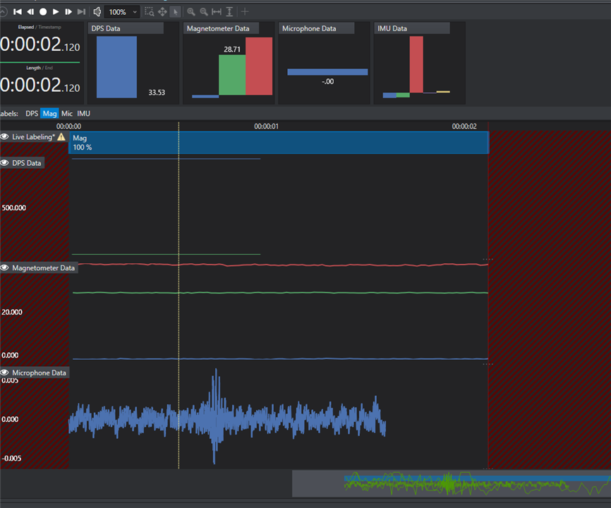
select part of the data block and fit label as prefefined before
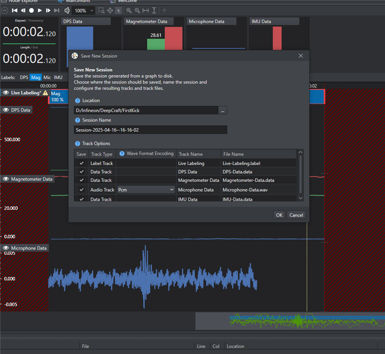
the save the live session, and tick select tracks
repeat the process for data streaming and saving the sessions.

3.3 Create one training project
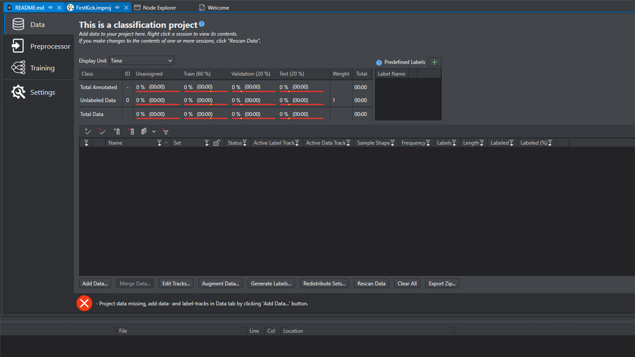
upload the data from the saved session files, scan the file for data
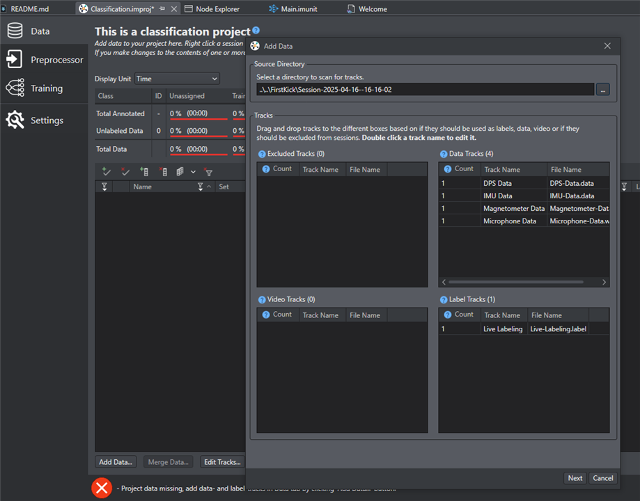
Now , the data is ready for training and modification
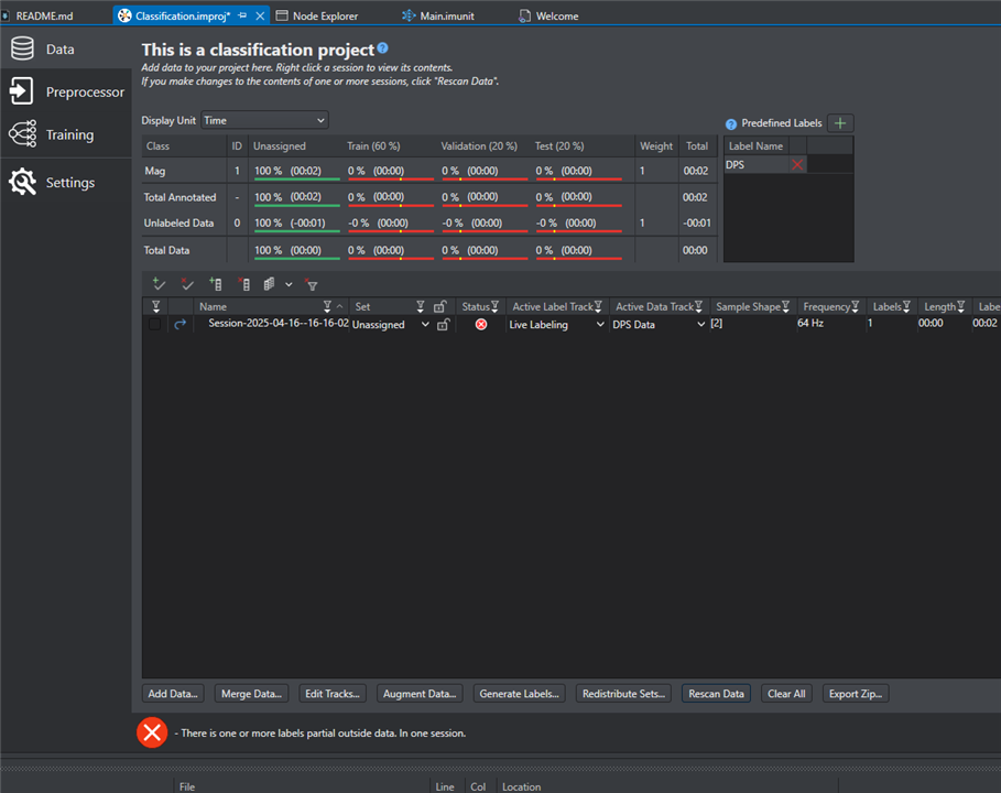
If the data is trained and the model is output. Go to coding.

4 PSoC 62S2 AI kits Deploy Model

4.1 Install the Modus Toolbox and install package with dashboard
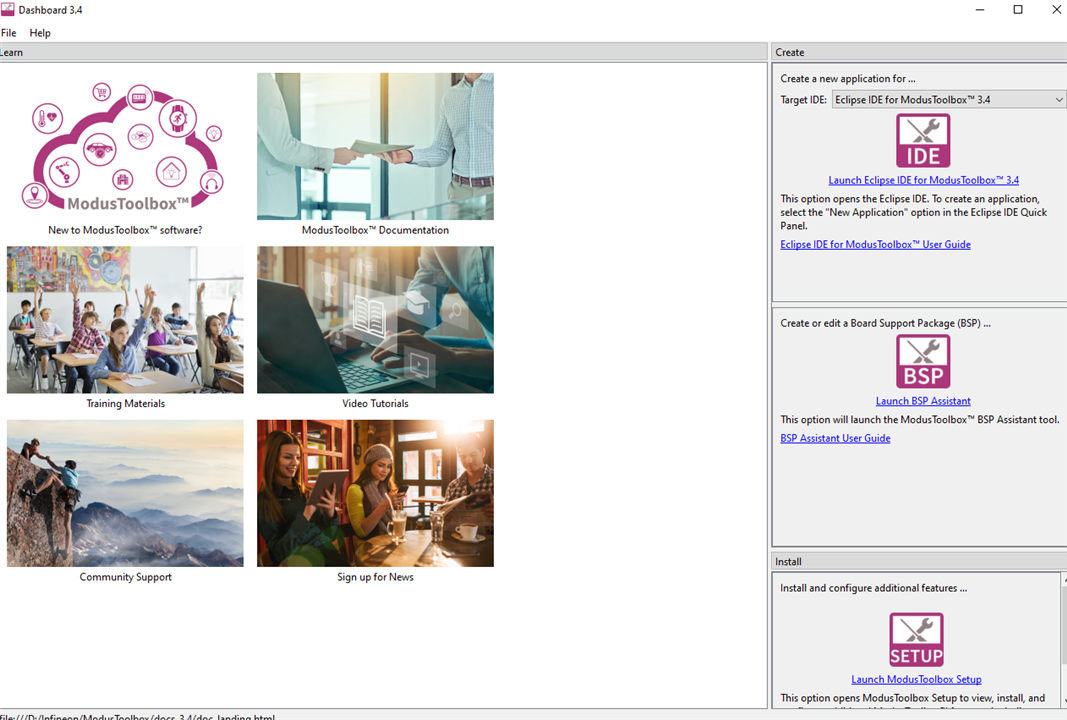
install packages
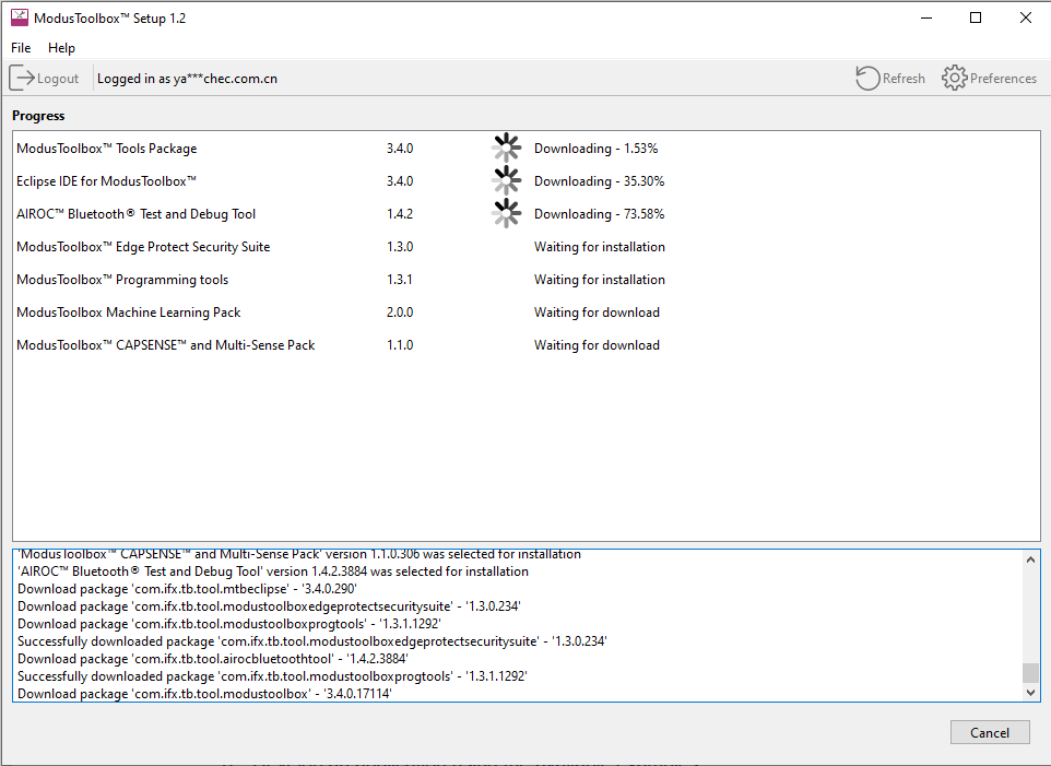
4.2 Coding

Start the Modus toolbox
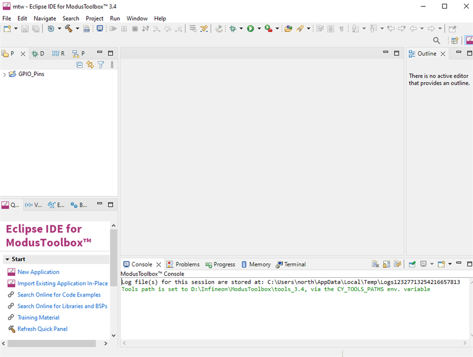
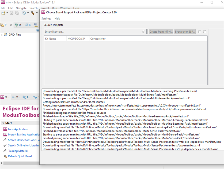
choose BSP 
import the simle GPIO toggle program to test the program, modify variables as windows 10 fits well
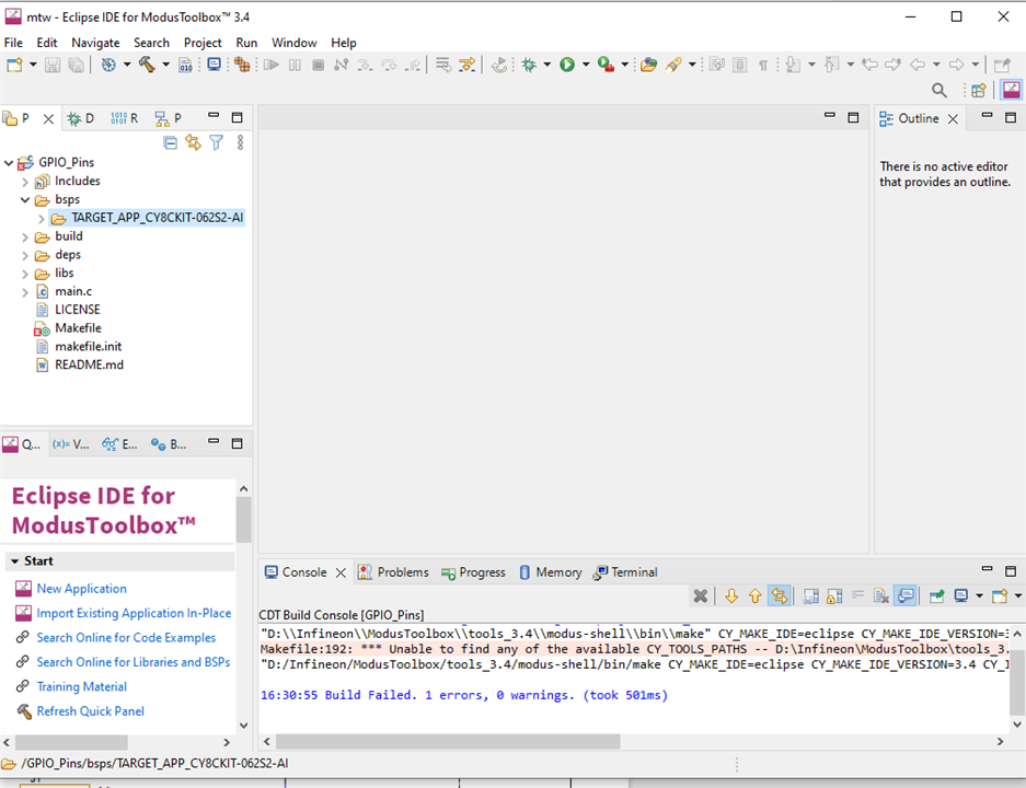
with parameter modified, the program can be built well
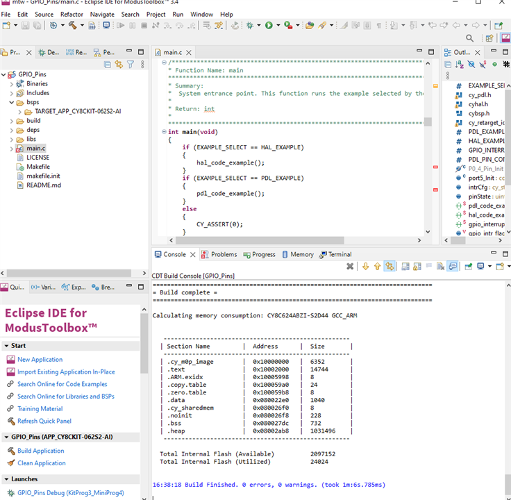
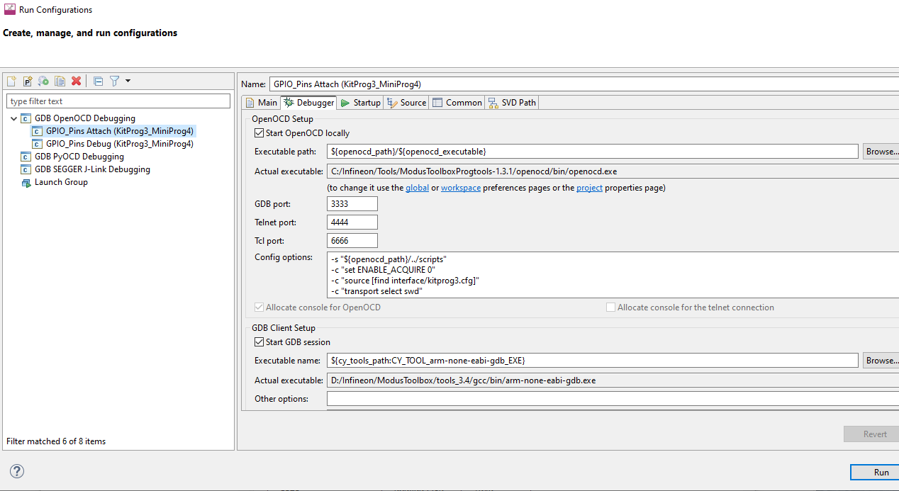
start run configuration and select kitProg3
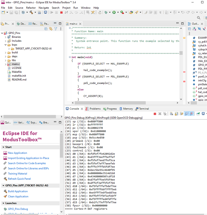
it can be flashed and runs
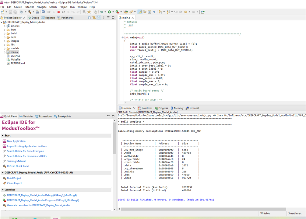
4.3 Import Deepcraft Studio model deployment program and build it
debug configuration
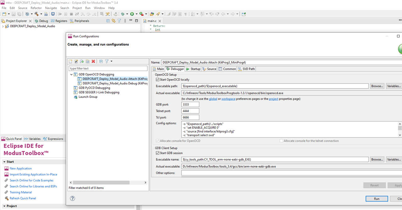
build and flash the program, it runs well
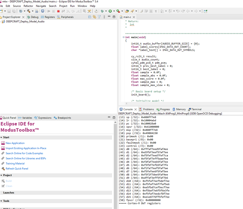
Open the Serial port for output
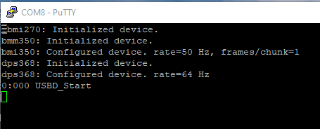
5 Summary

Quit interesting, this PSoC 62S2 AI kits is designed for DeepCraft studio,
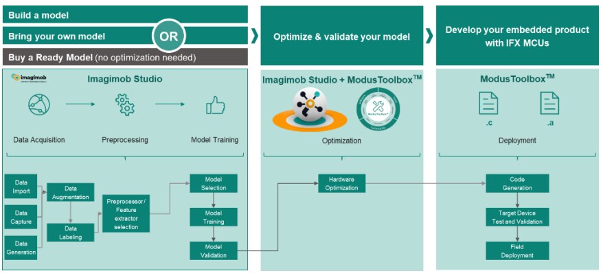
As above flow graph shows, it is well designed and relieve the workload with coding, and data collecting.

Just with one PSoC 62S2 AI kits, the Edge AI can be accomplished through, quick and easy. It can be scored 100% if I can, there is no peers and Every one would love it.

Anonymous