RoadTest: Seeking a Power Engineer to Evaluate the ROHM LogiCoA™ BUCK Converter
Author: meera_hussien
Creation date:
Evaluation Type: Development Boards & Tools
Did you receive all parts the manufacturer stated would be included in the package?: True
What other parts do you consider comparable to this product?: From my experience this product is one of a kind at the time of i am reviewing this product.
What were the biggest problems encountered?: No significant issues were encountered, as the documentation was clear and all required resources were readily available. The only limitation was the inability to program the microcontroller, which requires an additional programming device that appears to be sold separately.
Detailed Review:
 BUCK Converter – Product Review

Author: Hussien | Date: July 2025
The control of switching power supply circuit using digital controllers such as DSP (Digital Signal Processing) has been into practical use more than twenty years ago, but it has not become popular except in the fields of "switching power supplies with large power and high functionality" and "DC/DC converters requiring high-speed response". In particular most commercially available switching power supplies in 300W range (small to medium) are controlled by analog controllers.
This is because the high-speed, high-performance processors such as DSP consume a large amount of power and are expensive. Therefore, when a DSP is used in a switching power supply circuit with a small amount of power, the problems of "inefficiency" and "cost UP" become significant. To solve this problem, ROHM proposes to apply the analog-digital hybrid control (LogiCoA) to designs for switching power supplies, which bring out the advantages of analog control and digital control, and which can compensate for their disadvantages. Applying LogiCoA control enables to design a switching power supply that has the same power dissipation as analog control, while also offering superior digital-specific functions.
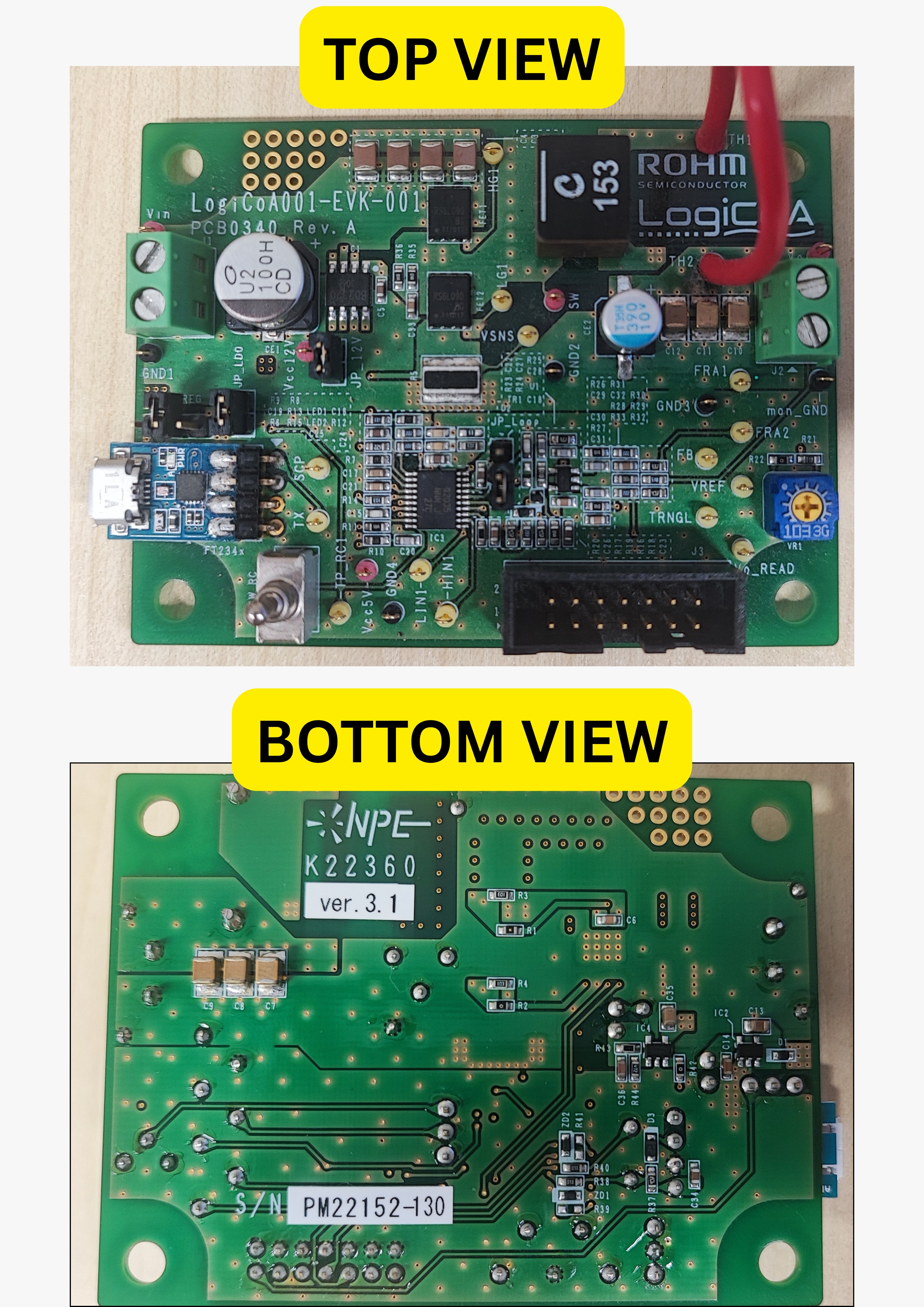
The ROHM LogiCoA BUCK Converter (part of the LogiCoA001-EVK-001 Evaluation Kit) is a next-generation compact power management solution, designed for efficiency, flexibility, and integration with various microcontroller-based and industrial applications. In this review, I’ll walk through its specifications, features, and my hands-on experience using basic electronics tools.
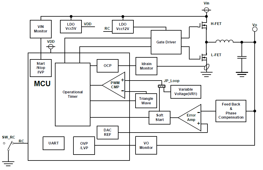
This EVK (Evaluation Kit) combines the LogiCoA series BUCK DC/DC converter and provides test points, jumper configurations, and pre-wired components for rapid validation. It helps engineers quickly evaluate the behavior of the BUCK converter without requiring deep circuit design experience. Figure 1 shows the overview of LogiCoA f LogiCoATM Power Solution. LogiCoATM Power is a solution adopting analog-digital hybrid control to a switching power supply and consists from 3 elements, (1) Microcontroller for Power Supply Control (LogiCoATM Microcontroller) ML62Q203x/ML62Q204x (hereinafter referred to ML62Q20xx group), (2) Operating System for Power Supply Control Microcontroller, RMOS, and (3) Power Supply Application. Refer to the explanation application note [1] for detail information of analog-digital hybrid control.
 Microcontrollers are suitable ones for power supply control with those analog-digital hybrid control is adopted and ML62Q2033/2035 and ML62Q2043/2045 are released. (at the time of this document’s release) On this EVK, ML62Q2035 is mounted. Refer to 4.2 MCU, the datasheet of ML62Q2033/2035/2043/2045 [2] and the user’s manual of ML62Q2033/2035/2043/2045 [3] for more detail information about ML62Q2035.
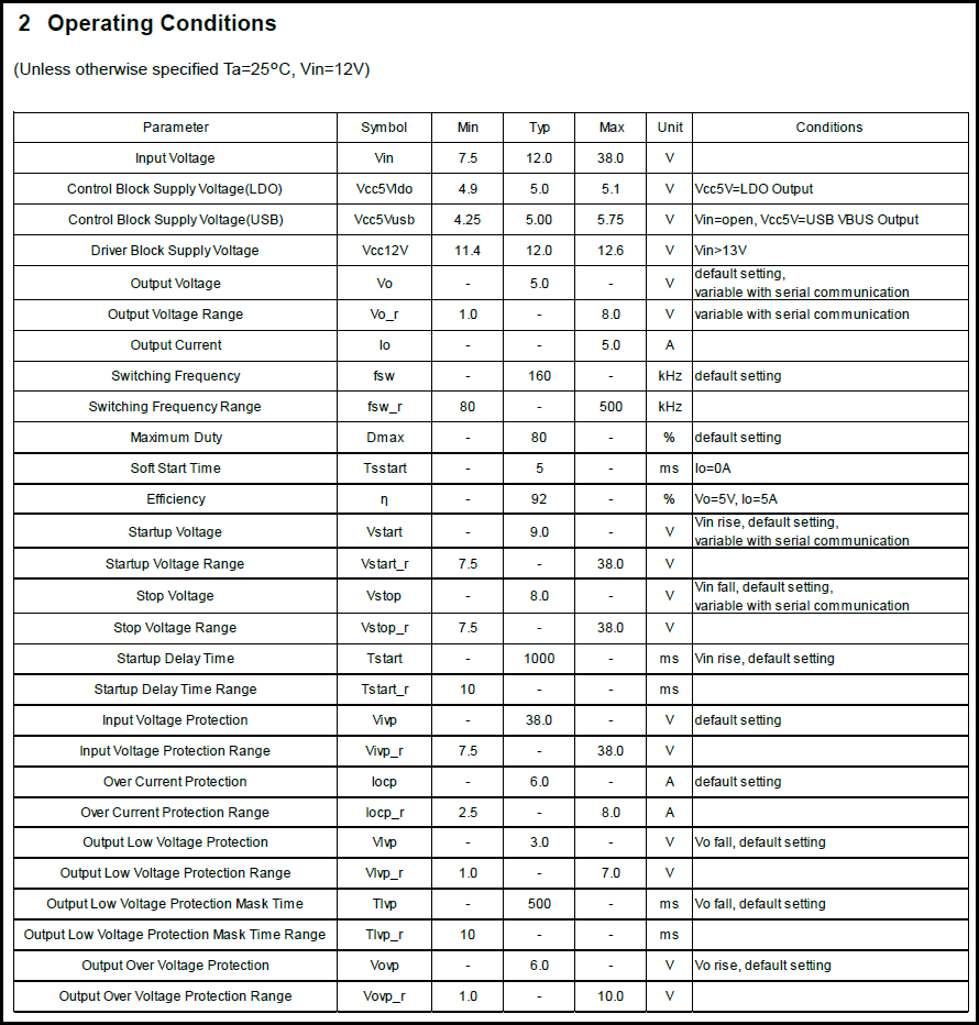
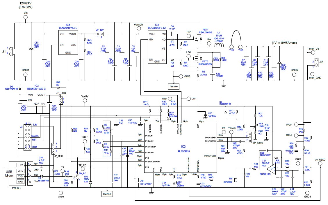
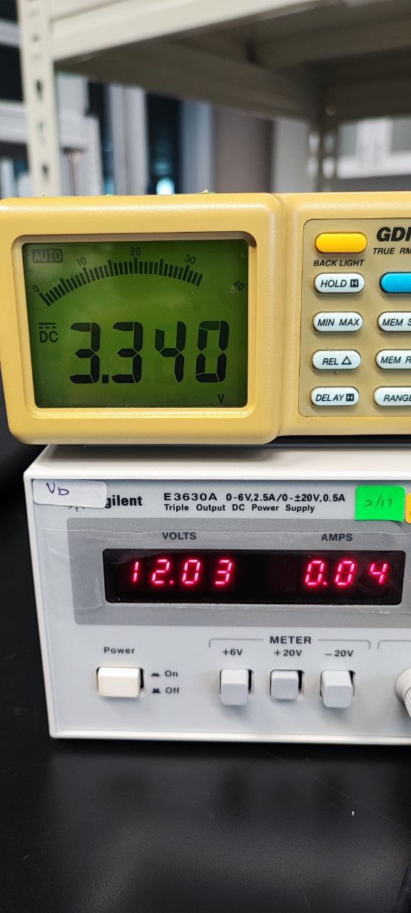
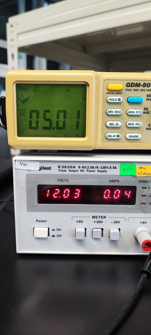
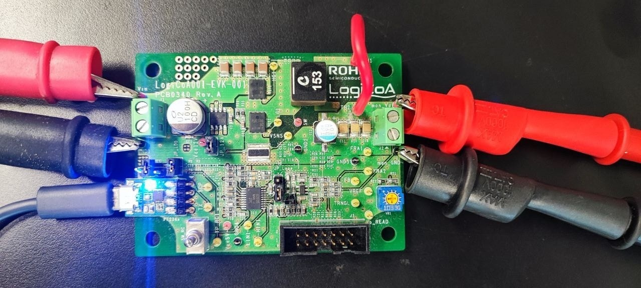
For the test setup, I have use the 12V as the input voltage and the measured voltage at output shows 5V (as per the quick start guide) . The configuration of the pins is as shown below:
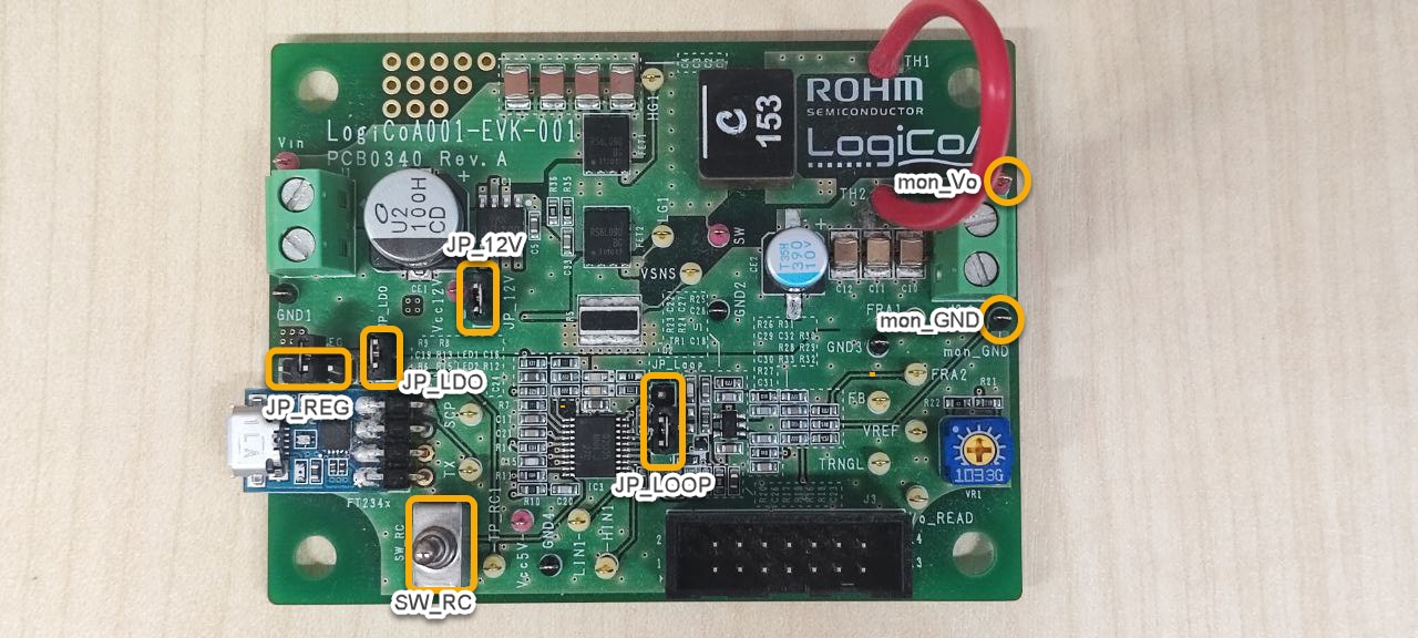
1) The jumper JP_LDO is shorted.
2) Jumper JP_12V is shorted.
3) Jumper JP_LOOP is shorted between Pin 2 and Pin 3.
4) And jumper JP_REG is left open.
5) Turn the SW_RC to connect Pin 1 and Pin 2.
6) Next connect the input power and ground at Vin and GND respectively. Make sure the power supply is turned off when connecting.
7) Lastly connect the multimeter to mon_Vo and mon_GND.
8) Turn on the power supply and observe the voltage output at multimeter.
The image below illustrate the test setup and the measured voltage.
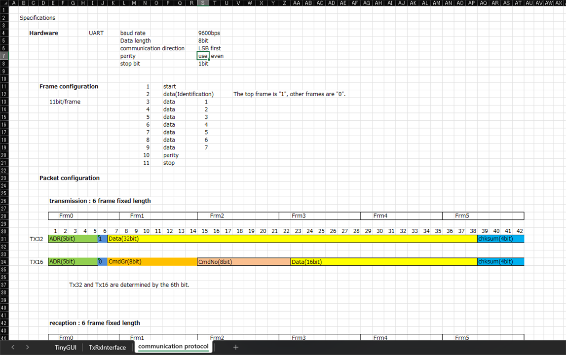
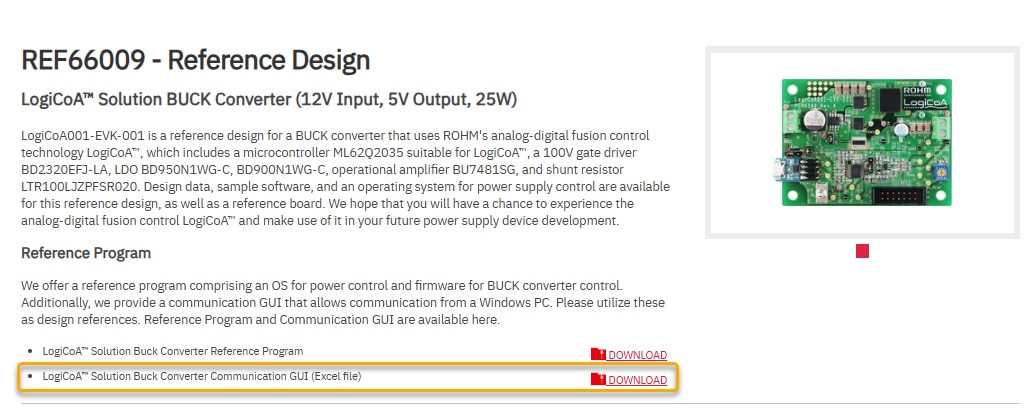
In the previous test we have successfully conducted the initial setup and conducted the test. In this section we would like to see the protocol for serial communications using UART, the communications functions and how to use the communication GUI developing environment. For this we need to download the excel file from the ROHM official site.
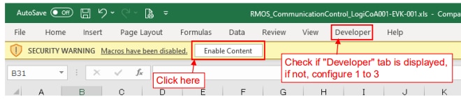
Of course registration is required prior to able to download the file. Once the file is downloaded, unzip and open the excel file. Since the excel files comes with Macro, it may me blocked if you are running it for the first time. In order to enable the macro, right click on the file and go to properties and tick the unblock. Once done, next we need to check whether the Excel is set up to use VBA macros. If ""Development" tab is displayed in Excel as shown below, VBA macro can be executed. In case the "Developer" tab is not displayed, it should be enabled first.
Follow the instruction below to enable the "Developer" tab
1. Click, "File" tab > "Options" > "Customize Ribbon".
2. Check "Developer" box in "Customize the Ribbon" list.
3. Click, "OK".
4. check the window that "Developer" tab is displayed

One's the excel is ready, we are now ready for test the board using the GUI. But before that it is better to understand the excel file. The excel file comes with 3 worksheet.
| {gallery}Excel |
|---|
|
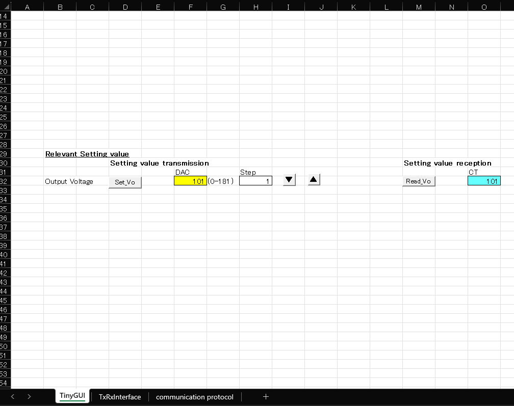
IMAGE TITLE: Worksheet 1 TinyGUI |
|
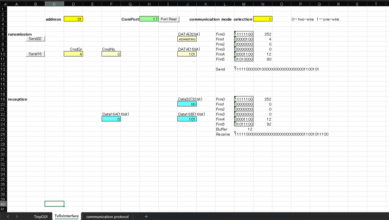
IMAGE TITLE: Worksheet 2 TxRxInterface |
|
IMAGE TITLE: Worksheet 3 Communication Protocol |
Of all the three worksheet, we will use the first worksheet which is the TinyGUI to control the output voltage. But before that we need ensure that the ROHM board is connected to the PC. Plug in the USB cable from the PC to the ROHM board. Next click "PORT READ" to get the correct port number. To ensure that the correct port is connected, we can double check in the device manager. As shown in the figure below
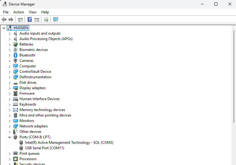
The port number shown in the device manager should match with the one shown in Worksheet 2 TxRxInterface. Once this is confirmed Go back to Worksheet 1 TinyGUI to set the output voltage. By referring to the manual, we know that the Vo of the buck converter is determined by the code of D/A converter and the following equation is established.
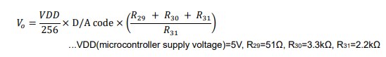
By referring to the equation above the output voltage Vo of the buck converter EVK can be changed using the setting code calculated from the above equation. For instance if we want to output 3.3V the D/A code should be 67. The image below shows the output voltage when the D/A code is 67 for and 101. The D/A code need to be inserted in the F32 cell and click the Set_Vo button.
The Test Setup
| {gallery}Voltage Output |
|---|
|
IMAGE TITLE: 3.3V |
|
IMAGE TITLE: 5V |
Lets examine the macro code behind each of this before we can create our own GUI using the excel. There are four different macro involved in this GUI.
For the Set_Vo the macro code is shown below
'---------------------------------------------------------------------------------------------------
'---------------------------------------------------------------------------------------------------
'   Vo Set
'---------------------------------------------------------------------------------------------------
'---------------------------------------------------------------------------------------------------
Public Sub Vo_Set()

    Worksheets("TxRxInterface").Range("D10") = "4"              'Set CmdGr
    Worksheets("TxRxInterface").Range("F10") = "0"              'Set CmdNo

    SetVal = Range("F32")                                       'Get setting value

    If SetVal > 181 Then SetVal = 181                           'Limit the upper limit of the setting value
    If SetVal < 0 Then SetVal = 0                               'Limit the lower limit of the setting value

    Range("F32") = SetVal                                       'Return setting value

    Worksheets("TxRxInterface").Range("J10") = SetVal           'Set "DATA"
    Call Worksheets("TxRxInterface").Send16                     'Execute communication

End Sub
For the increment of VoCT the macro code is as below
'---------------------------------------------------------------------------------------------------
'---------------------------------------------------------------------------------------------------
'   VoCT Up
'---------------------------------------------------------------------------------------------------
'---------------------------------------------------------------------------------------------------
Public Sub Vo_Up()

    Worksheets("TxRxInterface").Range("D10") = "4"              'Set CmdGr
    Worksheets("TxRxInterface").Range("F10") = "0"              'Set CmdNo

    SetVal = Range("F32")                                       'Get setting value
    SetVal = SetVal + Range("H32")                              'Add setting value
    If SetVal > 181 Then SetVal = 181                           'Limit the upper limit of the setting value
    Range("F32") = SetVal                                       'Return setting value

    Worksheets("TxRxInterface").Range("J10") = SetVal           'Set "DATA"

    Call Worksheets("TxRxInterface").Send16                     'Execute communication

End Sub
And for the VoCT down the macro code is as below'---------------------------------------------------------------------------------------------------
'---------------------------------------------------------------------------------------------------
' Vo Down
'---------------------------------------------------------------------------------------------------
'---------------------------------------------------------------------------------------------------
Public Sub Vo_Down()
Worksheets("TxRxInterface").Range("D10") = "4" 'Set CmdGr
Worksheets("TxRxInterface").Range("F10") = "0" 'Set CmdNo
SetVal = Range("F32") 'Get setting value
SetVal = SetVal - Range("H32") 'Subtract setting value
If SetVal < 0 Then SetVal = 0 'Limit the lower limit of the setting value
Range("F32") = SetVal 'Return setting value
Worksheets("TxRxInterface").Range("J10") = SetVal 'Set "DATA"
Call Worksheets("TxRxInterface").Send16 'Execute communication
End Sub
And lastly for the VoSet Read the macro code is as below'---------------------------------------------------------------------------------------------------
'---------------------------------------------------------------------------------------------------
' VoSet Read
'---------------------------------------------------------------------------------------------------
'---------------------------------------------------------------------------------------------------
Public Sub VoSet_Read()
Worksheets("TxRxInterface").Range("D10") = "4" 'Set CmdGr
Worksheets("TxRxInterface").Range("F10") = "0" 'Set CmdNo
Worksheets("TxRxInterface").Range("J10") = "65535" 'Set Arg
Call Worksheets("TxRxInterface").Send16 'Execute communication
Range("O32") = Worksheets("TxRxInterface").Range("J23") 'Get setting value
End Sub
By referring to the GUI above, i have created a custom GUI. Below is the screenshot of the GUI which i have created.
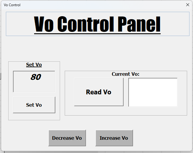
Basically what does the GUI does is that, it takes the value in the form D/A code and convert it to the desired voltage. The code for this GUI as shown belowPrivate Sub btnSetVo_Click()
' Ensure input is valid before setting
If IsNumeric(Me.txtSetVal.Value) Then
Sheets("TxRxInterface").Range("F32").Value = Me.txtSetVal.Value
Call Vo_Set
Else
MsgBox "Please enter a numeric value for Vo.", vbExclamation
End If
End Sub
Private Sub btnUp_Click()
Call Vo_Up
Me.txtSetVal.Value = Sheets("TxRxInterface").Range("F32").Value
End Sub
Private Sub btnDown_Click()
Call Vo_Down
Me.txtSetVal.Value = Sheets("TxRxInterface").Range("F32").Value
End Sub
Private Sub btnRead_Click()
VoSet_Read
Me.txtCurrentVo.Value = Sheets("TxRxInterface").Range("O32").Value
End Sub
Private Sub UserForm_Initialize()
' Load the last known value
Me.txtSetVal.Value = Sheets("TxRxInterface").Range("F32").Value
Me.txtCurrentVo.Value = Sheets("TxRxInterface").Range("O32").Value
End Sub
Based on my experience the ROHM LogiCoA Buck Converter is a very useful board. Definitely it would be very interesting to incorporate this in the future embedded work. I would personally would like to use this in my upcoming projects.