RoadTest: Seeking a Tech Enthusiast to Evaluate the Arduino GIGA Display Bundle
Author: JWx
Creation date:
Evaluation Type: Development Boards & Tools
Did you receive all parts the manufacturer stated would be included in the package?: True
What other parts do you consider comparable to this product?: STM32 Discovery kits including LCD displays (for example STM32H747I-DISCO) - when not counting Arduino IDE integration
What were the biggest problems encountered?: scarce external memory usage examples for third party libraries
Detailed Review:
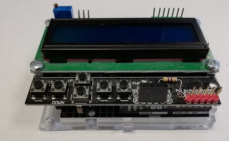
Long gone are days where Arduino was manufacturing only simple boards housing low-power 8-bit Atmel MCUs, but for many people Arduino is still Arduino Uno with user interface like below: several lines of text and a few buttons - very sensible for a processor with a few kilobytes of RAM, incapable of holding a buffer even for small graphical display, but limiting for some more advanced user-cases.
Another flagship product of them is Arduino IDE, where (by simply selecting different board) one can rebuild a code from, for example, 8-bit AVR clocked at several MHz to 32-bit dual core ARM.
This hardware abstraction works so great that Arduino have managed to extend 8-bit AVR based Arduino Uno family by Arduino Uno R4, using entirely different architecture (Arm Cortex M4) and achieved very good compatibility with both existing libraries and hardware modules (more information about it can be found - for example - in my roadtest of Arduino Uno R4 Minima).
So - considering that modern Arduino boards are much more powerful than several years ago and can be connected to high resolution displays - would it be possible to create modern, touch-based GUI using Arduino IDE and not spending months learning new frameworks? Or would hardware abstraction - limiting ways of interacting with silicon to some predefined common interface - make it impossible? Given the possibility to roadtest an Arduino GIGA R1 with Display Shield bundle I have decided to find out...
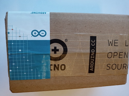
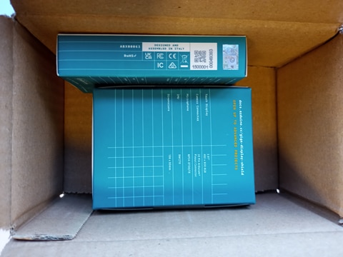
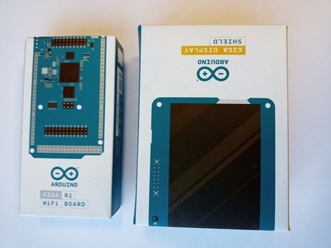
The hardware has arrived in Arduino branded cardboard box with two retail (with pretty graphical design outside) product boxes - one for Arduino and one for the shield - inside, but no additional filling.
| {gallery}Unboxing |
|---|
|
Outer box |
|
Outer box contents |
|
Inner boxes |
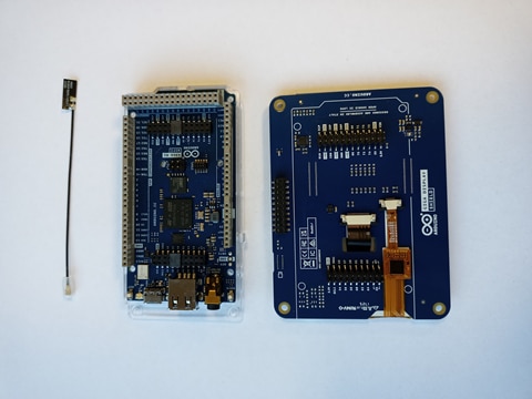
Arduino module was provided with plastic base and an antenna, but without any kind of ESD protecting bag, while LCD shield was protected by cardboard filling preventing the module from moving inside the box
| {gallery}Unboxing - modules |
|---|
|
Arduino board and accessories |
|
LCD module packaging |
|
LCD module |
|
All the components |
Those two modules can be connected together, but in somewhat unusual way.

When connecting, one should give caution that LCD shield connects from the BOTTOM of the GIGA board, which is handy because it leaves open access to the board's connectors but can be counterintuitive - boards are connected through via's in PCB, with connector on the opposite side. The same scheme is used with camera connector: camera module is installed on front side of Display shield, but it's connector is on the bottom side...
To prevent mistakes, removable indicators are installed over Display Shield connectors, but in my opinion they could be more attention-capturing (maybe with bright color or maybe an exclamation mark on the top).
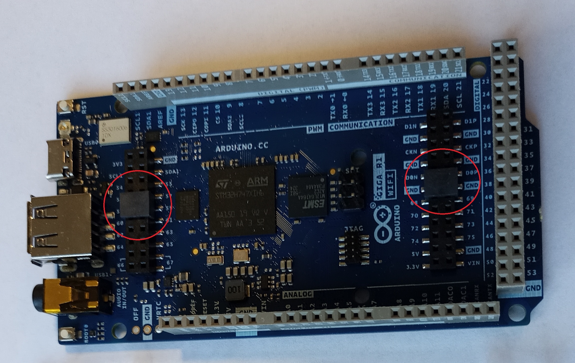
Arduino Giga R1 belongs to the same product line as Arduino Mega 2560 and Arduino Due - with form factor being an upgrade to the Arduino Uno, with more pins but the same easy way of prototyping by connecting either a shield or a set of DuPont cables.
Hardware configuration includes:
Considering MCU type and the on-board hardware, Arduino Giga R1 is very similar to Arduino Portenta H7 - to the level that it even shares some builtin examples. The same can be said about support - some issues can be addressed using solutions prepared for Portenta board.
Display shield is a dedicated extension to Arduino GIGA R1 including
As Arduino Giga R1 board support packages are present in both 1.8 and 2.x versions of Arduino IDE, my first test (remembering issues with UNO R4 on an unsupported system) was trying to connect it to Arduino IDE 1.8 running on MS Windows 7.
So far, so good - support package is present and can be installed without error:

but after connecting the board, serial port cannot be detected and OS complains about being unable to find a driver to a "Giga" device

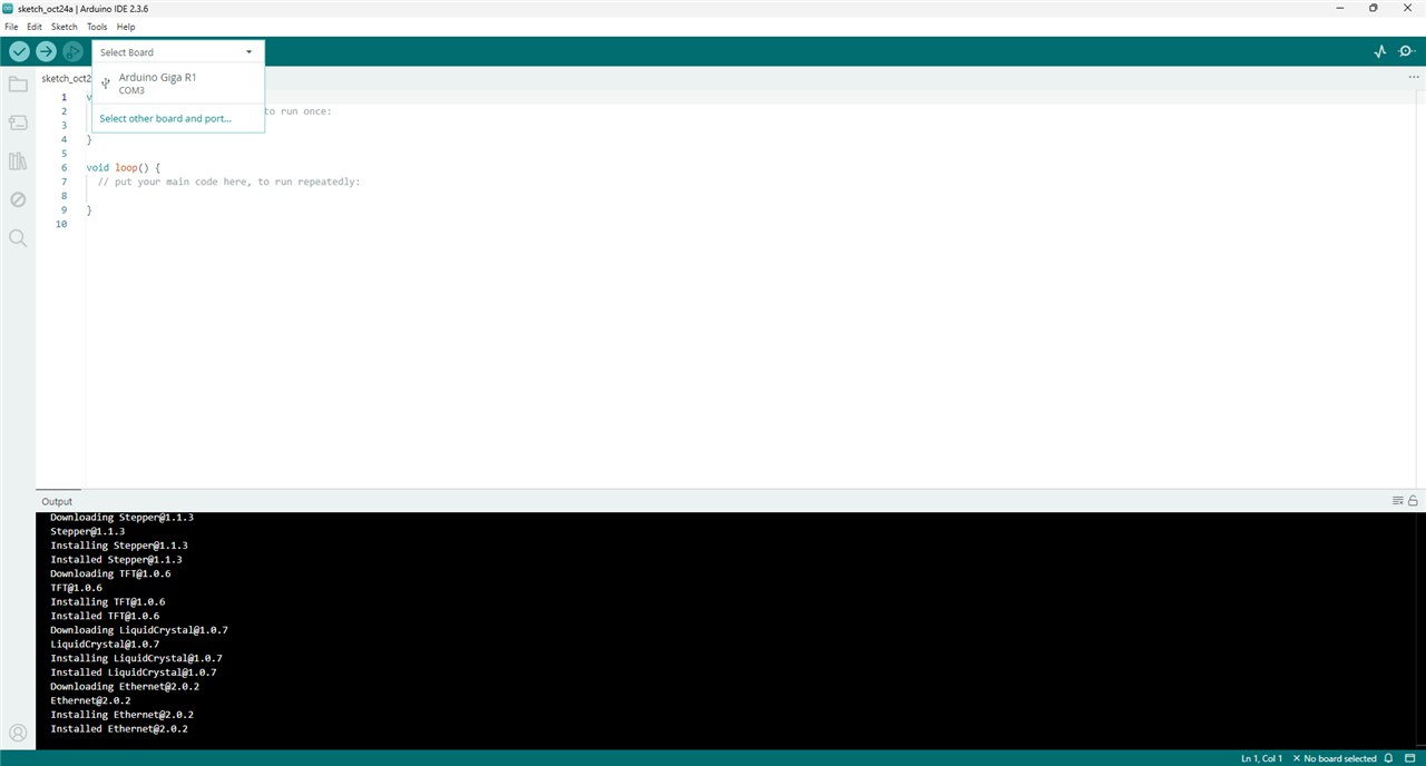
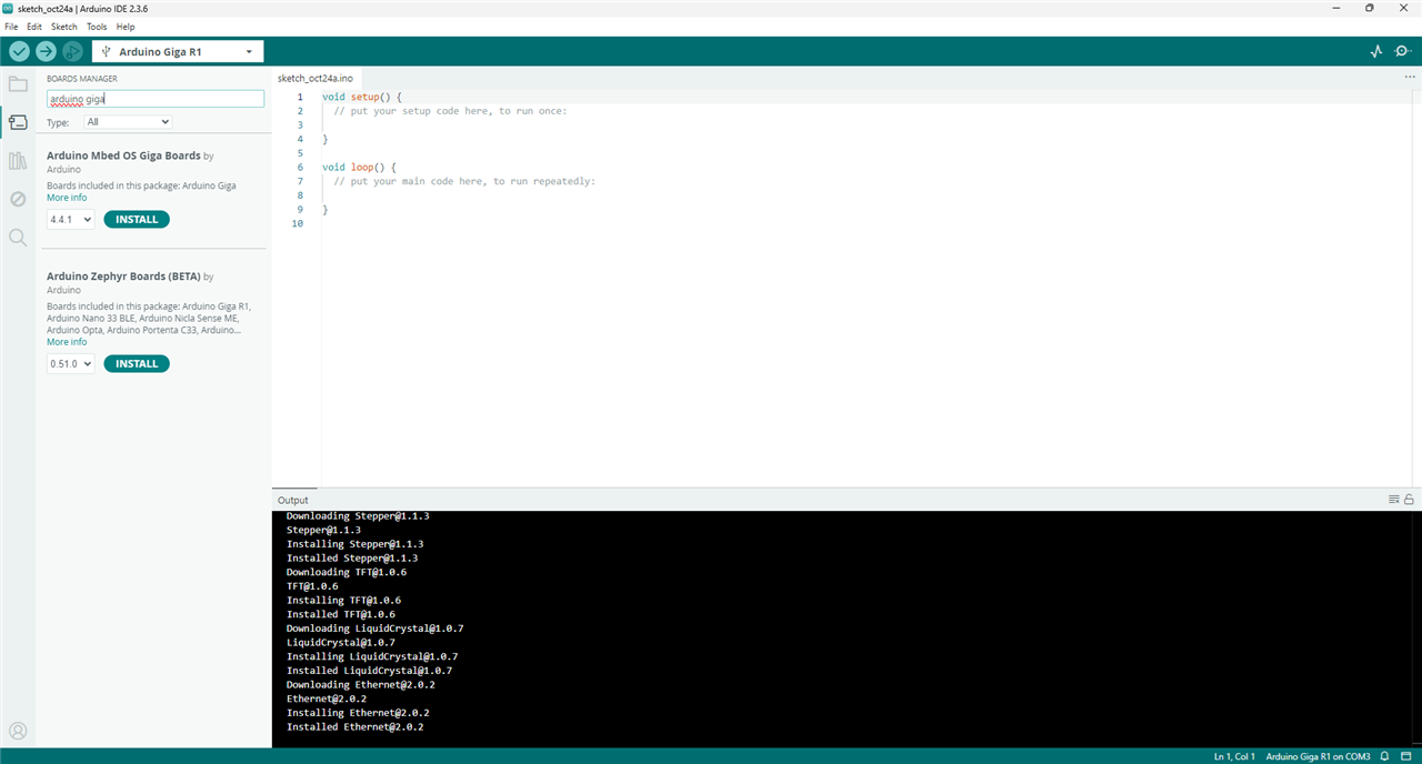
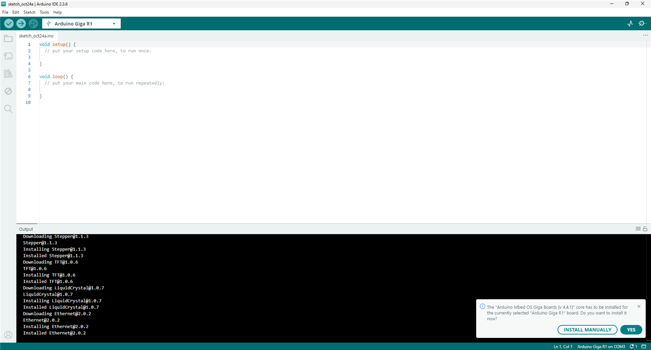
Much better results were achieved using Arduino IDE 2.3 and modern OS (MS Windows 11) - board was detected and two support packages were found: Arduino Mbed OS Giga Boards and Arduino Zephyr Boards (BETA)
| {gallery}Arduino IDE2 board detect |
|---|
|
Board detected |
|
Two support packages |
|
Default package installation |
Existence of two support packages can be explained by the fact that (according to the official website) Mbed OS would reach End Of Life in July 2026, staying open source but without maintenance nor support from the manufacturer (ARM), so an alternative solution is probably being prepared.

As Zephyr package is currently in Beta with limited library support, rest of the testing was conducted using Mbed package.
Arduino GIGA is based on two-core MCU: primary processor is Arm M7 and secondary is Arm M4. M7 core is always-active and M4 needs to be activated before use.
Arduino IDE allows for use of both cores for user code, abstracting them as two separate boards.
Internal FLASH memory can be divided between those two cores or a secondary core can be booted from the external SDRAM (after copying firmware there).
After deciding FLASH memory sharing strategy between cores:
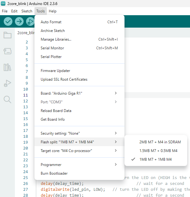
different sketches can be flashed to both of them:

There is a possibility to identify the core on which the code is running, so dual-core blink demo blinking different color LED with core-specific frequency can be achieved using code as simple as below (which needs be flashed two times: once for each core):
#include <RPC.h>

unsigned int delay_time;
uint16_t led_pin;

void setup() {
  RPC.begin();
  if (RPC.cpu_id() == CM7_CPUID) {
    //set RED LED and 1 Hz blink frequency
    delay_time = 500;
    led_pin = LEDR;
  } else {
    //set blue LED and 0.5 Hz blink frequency
    delay_time = 1000;
    led_pin = LEDB;
  }
}

void loop() {
  digitalWrite(led_pin, HIGH);  // turn the LED on (HIGH is the voltage level)
  delay(delay_time);            // wait for a second
  digitalWrite(led_pin, LOW);   // turn the LED off by making the voltage LOW
  delay(delay_time);            // wait for a second
}
Inter-core communication can be established using Remote Procedure Call (RPC) library, so even more complicated setups can be prepared, for example: one low latency process running on one core communicating with computation-intensive task running on the second core.
Arduino GIGA R1 is equipped - like Portenta H7 - with 8MB of external RAM. It can be used for booting an M4 MCU core, as additional area for dynamic memory allocation or as a static buffer for calculations or a farmebuffer.
It needs initialization before use and allocation/deallocation is using dedicated methods, but after that it can be accessed using standard pointers, so changes to the existing code can be limited.
Example code is as below:
#include "SDRAM.h:
/* leave first 2MB for static allocation */
SDRAM.begin(SDRAM_START_ADDRESS + 2 * 1024 * 1024);
unsigned char* = (unsigned char*)SDRAM.malloc(1024 * 1024);
My goal in this roadtest was to try to use standard graphic libraries with support for different MCU families, which could be used in different projects when learned - even Arduino hardware is using MCUs from different vendors, so limiting oneself to, for example, dedicated ST software would be a problem when the next board would be using Renesas MCU. After review of libraries provided with Arduino IDE, two software stacks were selected for a test:
Both of them can be used with different MCU families of different vendors, LVGL being open-source and (commercial) emWin being provided by hardware providers free of charge when used with their silicon.
Arduino GIGA libraries include sample sketches for Segger emWin and LVGL graphical libraries
LVGL demo
Segger emWin demo
As can be seen, both libraries deliver widgets of similar aesthetics, with maybe emWin components being more polished.
As of usage potential, LVGL is a MIT licensed software, widely used and ported to different processor families.
In other way, Segger emWin is a proprietary product with wide hardware support, version of which was bought by ST and made available for use with their MCUs - and Arduino port based on this version can be downloaded using Arduino IDE. The library consists of precompiled binary (in this case shipped for Cortex-m7 architecture only), header files and some configuration code. Being proprietary product, there is some small probability of licensing conflict with the rest of the code - but even in extreme cases it can be resolved by separating code to different cores of Arduino Giga (one running the GUI and another running code with conflicting licensing).
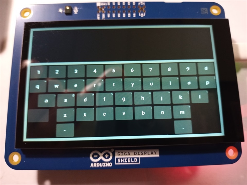
Both demos compiled and ran correctly, but when more complicated widget (on-screen keyboard) was tried, both frameworks generated firmware fault conditions (black screen and red LED blinking in sequence: four slow blinks followed by four fast blinks), requiring double-reset recovery before next flashing.
After some research it turned out to be memory-related issue:
800x480 LCD requires between 375kB (for 8bpp color) and 1.5MB (for 32bpp) for full-screen buffer, doubling this value when double-buffering (technique involving using two buffers and making modifications in inactive one, then switching - which greatly reduces number of display artifacts). Considering that GIGA MCU has 1MB of internal RAM, it is easy to encounter out of memory condition.
Fortunately, Arduino GIGA comes equipped with 8MB of external SDRAM, which - according to the documentation - can be used as a framebuffer, but it is not something out-of-the-box and needs additional configuration.
For emWin library no working solution was found - when disabling double-buffering, static keyboard image was drawn before crash, and attempts to reallocate video memory to SDRAM have failed (producing either nothing or excessive graphical artifacts), but keyboard itself looks impressive:
For LVGL it turned out to be simple configuration issue - library is installed unconfigured and lv_conf.h needs to be created, including (for example) following lines:
#define LV_MEM_SIZE (2 * 1024 * 1024U)
#define LV_MEM_ADR SDRAM_START_ADDRESS
and trimming SDRAM size in main code to exclude part dedicated for video memory
SDRAM.begin(SDRAM_START_ADDRESS + 2 * 1024 * 1024);
resulting in an operational keyboard
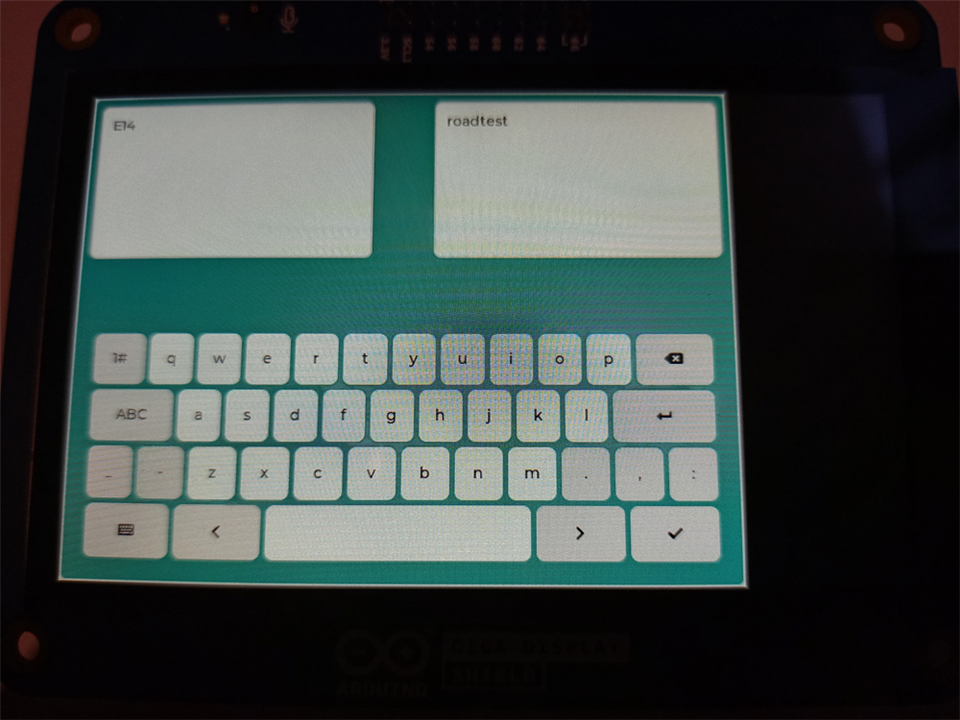
working like this
which paved way to explore more examples from official LVGL documentation, producing widgets like compass below (unfortunately Arduino Giga Display Shield builtin Inertial Measurement Unit doesn't include magnetometer, preventing us from having working compass out of the box):
At this stage another question arises - could there be a better way of prototyping a GUI than laboriously specifying placement of each widget in the code? Maybe some WYSIWYG (What You See Is What You Get) application allowing for graphical placement of widgets on the screen?
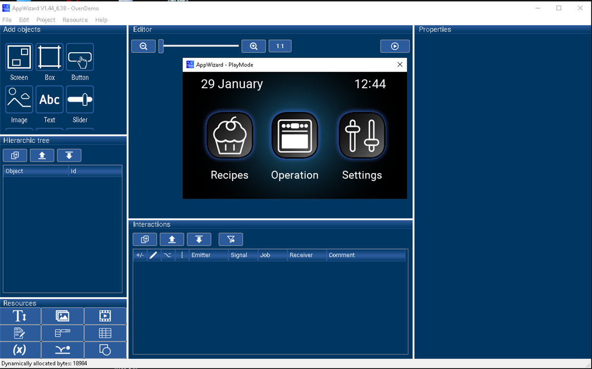
Segger has such a software - it is called AppWizard and is even probably possible to use free of charge with Arduino GIGA as it is STM32 MCU based. Unfortunately, to use it, emWin library runtime problems should be addressed first - but it looks very nice (demo project below)
NXP has similar software for LVGL - it is called GUI Guider, but is licensed to use free of charge only with NXP products, so only a screenshot from the manufacturer's page can be presented:

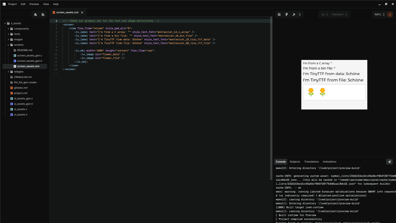
another possibility is LVGL Editor from LVGL PRO package that has free license for "personal use, open-source projects and education" but it is XML editor, not WYSIWYG we are looking for
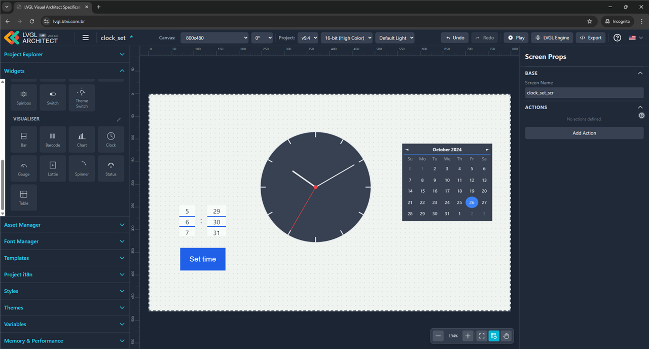
Another one is LVGL Architect - an online tool, according to the forum posts, still under development. It allows for drag-and-drop GUI creation, but results are somewhat mixed. Below is a project of clock setting screen
using project file as below:
that can be exported as a Arduino .ino project, but with initial results not very encouraging
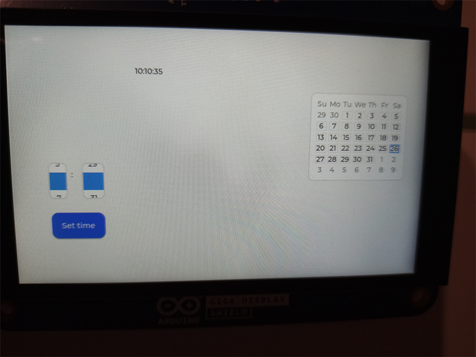
it seems that a clock widget (not present in the LVGL but built as an use-case of scale widget with two indicators in one of the examples) is only placed as an placeholder label and the rollers of the desired size are too small to be displayed correctly. Additionally, most of the operation logic have to be added by hand.
Correcting size of rollers allowed for correct selection of time to be set:
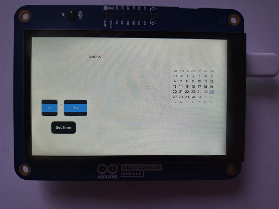
an integrating it with a clock from clock example code resulted in GUI like below:
Which proves that there is currently possibility to quickly create usable GUI, even without help of web designer.
Next interesting feature of the module is 3D support which is provided by TinyGL library, with one of examples looking like below:
Arduino GIGA R1 with Display Shield is an interesting option for creating modern, touch based graphical interfaces, using Arduino IDE and standard libraries. There is currently somewhat limited documentation for using external RAM as an display memory but most of third-party code works and there are even available free graphical design tools for quick prototyping.
The kit itself could make use of somewhat more packaging/filler material and the method of connecting modules could be better indicated on boards themselves (some people use manuals only in last resort) but it is overall very nice addition to the Arduino family, allowing for creation of more user-friendly appliances and toys.