RoadTest: Seeking a Tech Enthusiast to Evaluate the Arduino GIGA Display Bundle
Author: ralphjy
Creation date:
Evaluation Type: Development Boards & Tools
Did you receive all parts the manufacturer stated would be included in the package?: True
What other parts do you consider comparable to this product?: Waveshare ESP32-S3 4.3inch Capacitive Touch Display Development Board B, 800×480 Resolution, 5-Point Touch, 32-Bit LX7 Dual-Core Processor, 240MHz
What were the biggest problems encountered?: Software libraries are incomplete. Poor API documentation.
Detailed Review:
This roadtest is a bit different from the ones that I’ve done in the past in that I’m evaluating the Giga Display bundle performance relative to an application that I’m developing.
I've been interested in Human Machine Interfaces (HMI) since the advent of small portable interactive displays. I've mainly used them for sensor monitoring and control, but now that I have a grandson who is 3 years old, I'd like to make visual/audible interfaces that he can interact with.
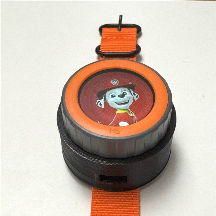
He is a fan of the Paw Patrol cartoon pups and I made him a wrist mounted display using an M5Stack M5Dial round display with rotary encoder. I wasn't able to implement much more than a display that showed the different characters as you rotated the dial. The Arduino Giga Display bundle would be a nice way to add a handheld HMI component to interface with the wrist display and provide additional audio and imaging capabilities.
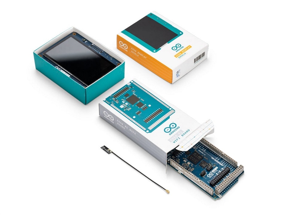
There really isn't much to show with the unboxing. The Arduino Giga R1 and the Giga Display Shield were individually packaged in typical Arduino boxes. The only additional component was a small WiFi antenna that was included with the Giga R1.
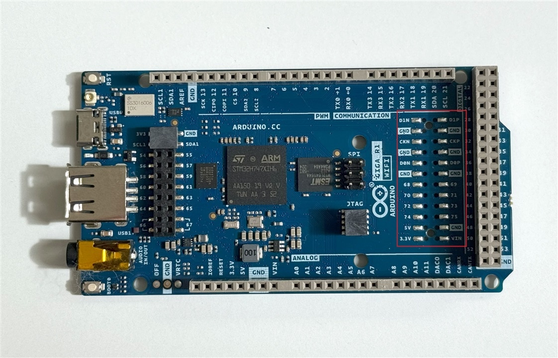
I had a couple of issues with the Giga R1 that I received. The first was that the WiFi antenna had been crushed by the Giga R1 when it was packed in the box and more significantly the Giga R1 board was missing one of the passthrough connectors used to mount the Display Shield. This is shown outlined in red.
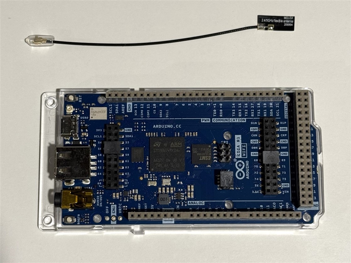
Fortunately, cstanton was able to get Arduino to send me a replacement which I received in about 2 weeks which is shown below.
Other than that there weren't any issues with what I received. The one surprise that I had was that the display mounts on the bottom of the Giga rather than the top. It makes sense since that allows access to the socket headers on the top of the Giga so that other shields could be used with the display.
I saw a Hackster project that used a ProtoStax case. It's a nice sturdy acrylic case with removeable sides, so I decided to buy a case rather than print one in order to save some time. I got the obsidian case with the tripod mount and camera cutout. Here a picture of the Giga R1 and Display Shield in the case on a tripod running the ProtoStax LVGL demo.
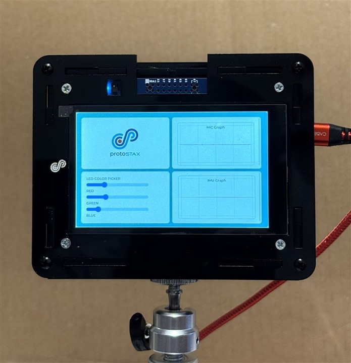
The case did not come with a camera housing, so I printed one to protect the camera.
And a video showing the demo using LVGL widgets to show sliders used to set the RGB LED color and graphs to display the microphone and IMU functions.
For the application that I want to implement I'd like the following functions:
There are quite a few boards available (I am only considering MCUs, not SBCs with OS capability). I made a comparison table of other ones that I had looked at that had similar capabilities. I haven't found one that checks all the boxes.
| Requirements | Capabilities | ||
| Arduino Giga Display Bundle | Waveshare ESP32-S3-Touch-LCD-3.5 | Waveshare ESP32-S3-Touch-LCD-4.3B-BOX | |
| Processor & Memory | |||
| MCU | STM32H747XI Dual Core 32bit (M7 480MHz/M4 240MHz) |
ESP32-S3 Dual Core 32bit (LX7 dual core/240MHz) |
ESP32-S3 Dual Core 32bit (LX7 dual core/240MHz) |
| MCU memory | 1MB SRAM + 2MB Flash | 512KB SRAM +384KB ROM | 512KB SRAM +384KB ROM |
| External memory | 16MB Flash + 8MB SDRAM | 16MB Flash + 8MB PSRAM | 16MB Flash + 8MB PSRAM |
| User Interface | |||
| Touchscreen GUI | 3.97” IPS 480x800 RGB 16.7M Color 5-point capacitive touch |
3.5” IPS 320x480 RGB 262K Color 5-point capacitive touch |
4.3" 480x800 RGB 65K Color 5-point capacitive touch |
| Audio Input | PDM microphone (on Display shield) | PDM microphone | NA |
| Audio Output | Stereo headphone output | Mono amplifier output | NA |
| Image Capture | SPI camera interface | SPI camera interface | NA |
| Image Display | Touchscreen | Touchscreen | Touchscreen |
| Connectivity & Communications | |||
| WiFi/Bluetooth | 2.4GHz WiFi + BLE 5 | 2.4GHz WiFi + BLE 5 | 2.4GHz WiFi + BLE 5 |
| USB (power + data) | USB-C | USB-C | USB-C |
| Storage | |||
| USB or SD | USB 2 Host | SD card | SD card |
| Portability | |||
| Handheld (size & weight) | 127mmx102mmx38mm (ProtoStax case) | 96mmx64mmx15mm | 116mmx79mmx18mm |
| Rechargeable battery | NA | 3.7V LiPo (not installed) | 3.7V LiPo (not installed) |
| Other | |||
| RTC | Integrated on MCU | PCF85063 | PCF85063 |
| IMU | BMI270 6-axis (on Display Shield) | QMI8658 6-axis | QMI8658 6-axis |
| Cost | $116 | $36 | $58 |
My initial plan was to evaluate the Giga Display bundle against each of the requirements in terms of both hardware and software capabilities and then implement an integrated application to interact to the wrist display. As I got into the roadtest I realized that there are significant issues with the state of the current Arduino software in terms of simultaneously integrating some of the hardware interfaces. As a result I've decided that I cannot implement the application. I'll discuss the issues in the functional sections.
Just for reference here was my intended application. I may try it with a different board.
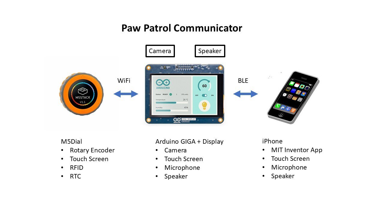
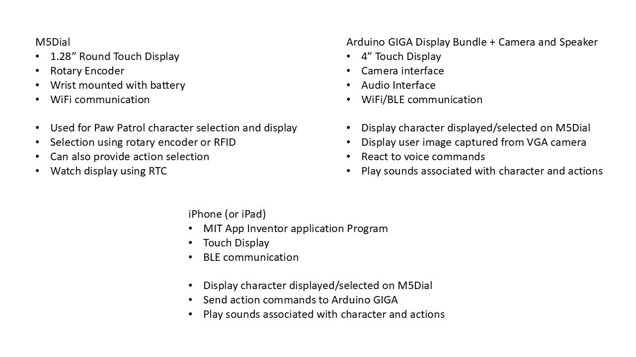
I'll partition the review into these sections:
As a general note, Doug Wong is also doing a review of the Giga Bundle and he has posted quite a few useful blogs using library examples that he has modified to work. I found it helpful to use some of that code as a starting point and if I show any of that code that I tweaked, I'll add the _DW suffix.
Here are a picture and a video of the wrist display. The rotary encoder display is really intended for panel mounting, so it sits really high on the wrist. It lacks an audio amplifier and speaker, so adding sound would have been difficult. The biggest drawback is that even though it has battery support, the largest battery that I could shoehorn in was 35mAH.
In the Giga Display Shield Tutorials there is a Display Image from USB example that shows a list of images on the the USB drive that you can select for display by using the Serial Monitor input. Doug adapted this to add the ability to toggle images using a screen touch. This was a useful example that incorporated the display, touchscreen, and USB drive functions, so I chose that as a good place to start. Only a small tweak to Doug's example to adapt to the specifics of my drive volume and directory.
GigaDisplay_ImagesfromUSB_Touch_DW.ino
// Arduino GIGA R1 program to display images stored on a USB memory device
// by Doug Wong 2025
// Touching the screen displays the next image
// The image will roll over to thr first image after the last image
// Image format should be 800 x 480 in RGB565 format - binary

#include <Arduino_USBHostMbed5.h>
#include <DigitalOut.h>
#include <FATFileSystem.h>
#include <Arduino_H7_Video.h>
#include <ArduinoGraphics.h>
#include <Arduino_GigaDisplayTouch.h>

Arduino_GigaDisplayTouch touchDetector;

USBHostMSD msd;
mbed::FATFileSystem usb("GIGA");

const int USB_HOST_ENABLE_PIN = PA_15;
const int MAX_FILES = 50;
const int MAX_NAME_LEN = 128;
char fileNames[MAX_FILES][MAX_NAME_LEN];
int fileCount = 0;
const int MAX_CONNECTION_ATTEMPTS = 10;
int filenum = 0;                        // file number selected

Arduino_H7_Video Display(800, 480, GigaDisplayShield);
const int IMG_WIDTH = 800;
const int IMG_HEIGHT = 480;
const uint32_t EXPECTED_FILE_SIZE = IMG_WIDTH * IMG_HEIGHT * 2;

uint8_t rowBuffer[IMG_WIDTH * 2]; // Static buffer

void setup() {
    Serial.begin(115200);
    touchDetector.begin();
    pinMode(USB_HOST_ENABLE_PIN, OUTPUT);
    digitalWrite(USB_HOST_ENABLE_PIN, HIGH);
    //while (!Serial) {}
    delay(1500);

    Serial.println("=== USB File List ===");
    Display.begin();
    forceScreenClear();

    if (!initUSBHost() || !mountUSB()) return;
    listRootDirectory();
    if (fileCount == 0) return;

    printFileList();
    Serial.println("Select a file # to open as 800x480 .bin, or type 'clear' to reset the screen:");
}

void loop() {
    if (fileCount > 0) handleUserInput();
    uint8_t contacts;
    GDTpoint_t points[5];

    contacts = touchDetector.getTouchPoints(points);  //capture touches on touchscreen
    if (contacts > 0) {                               //Check for screen touch
        filenum++;                                    //increment filenumber
        if (filenum > fileCount)  filenum = 1;        //handle rollover when filenum exceeds filecount
        displayRawRowByRow(fileNames[filenum-1]);     //call image disply of file number
    }
    contacts = touchDetector.getTouchPoints(points);  //check screen for touches - should br none at this time
    contacts = 0;                                     //clear any touch count anyway
    delay (20);
}

bool initUSBHost() {
    for (int i = 0; i < MAX_CONNECTION_ATTEMPTS; i++) {
        if (msd.connect()) {
            Serial.println("USB mass storage device connected!");
            return true;
        }
        Serial.println("USB device not detected, retrying...");
        delay(1000);
    }
    return false;
}

bool mountUSB() {
    Serial.print("Mounting USB device... ");
    if (usb.mount(&msd)) {
        Serial.println("Failed to mount USB.");
        return false;
    }
    Serial.println("done.");
    return true;
}

void listRootDirectory() {
    fileCount = 0;
    DIR* dir = opendir("/GIGA/imagesLE/");
    if (!dir) return;
    while (fileCount < MAX_FILES) {
        struct dirent* entry = readdir(dir);
        if (!entry) break;
        strncpy(fileNames[fileCount], entry->d_name, MAX_NAME_LEN - 1);
        fileNames[fileCount][MAX_NAME_LEN - 1] = '\0';
        fileCount++;
    }
    closedir(dir);
}

void printFileList() {
    Serial.print("Found "); Serial.print(fileCount); Serial.println(" file(s) in /GIGA/:");
    for (int i = 0; i < fileCount; i++) {
        Serial.print(i + 1); Serial.print(") "); Serial.println(fileNames[i]);
    }
}

void handleUserInput() {
    if (Serial.available() > 0) {
        String input = Serial.readStringUntil('\n');
        input.trim();

        if (input.equalsIgnoreCase("clear")) {
            forceScreenClear();
            return;
        }

        int sel = input.toInt();
        if (sel < 1 || sel > fileCount) return;

        Serial.print("Displaying: /GIGA/");
        Serial.println(fileNames[sel - 1]);

        displayRawRowByRow(fileNames[sel - 1]);
    }
}

bool displayRawRowByRow(const char* fileName) {
    String path = "/GIGA/imagesLE/" + String(fileName);
    FILE* f = fopen(path.c_str(), "rb");
    if (!f) return false;

    forceScreenClear();
    Display.beginDraw();

    for (int y = 0; y < IMG_HEIGHT; y++) {
        if (fread(rowBuffer, 1, IMG_WIDTH * 2, f) != IMG_WIDTH * 2) break;
        Image rowImage(ENCODING_RGB16, rowBuffer, IMG_WIDTH, 1);
        Display.image(rowImage, 0, y);
    }

    Display.endDraw();
    fclose(f);
    Serial.println("Image displayed successfully!");
    return true;
}

void forceScreenClear() {
    Display.beginDraw();
    Display.fill(0x0000);
    Display.endDraw();
}
A short video cycling through three 800x480 images that I'm using for demo. The first is my grandson, the second is the Paw Patrol wrist display and the third is the aqueduct in Segovia. In the video I first use the Serial monitor input to select the images and then use the touch input to cycle through them. There's a nice reflection of the webcam I'm using to record this in the glossy display screen when there is no image displayed  . I am going to get an anti-glare screen protector to see if I can improve that.
For the communicator I really wanted to select a thumbnail image to evoke an action (contact a character, play audio or video, etc.). I am familiar with LVGL, so that seemed a good choice for a GUI. This began a somewhat unpleasant journey in the current state of the Arduino Giga software and documentation. The Giga R1 is a couple of years old and there is the usual problem of encountering example programs that no longer work with the current software versions. To be fair, there are a lot of tutorials for the Giga Display Shield. It seems that Arduino started down a path of trying to make the GigaDisplay easier to program, but hasn't quite finished. A basic problem is knowing which libraries to use and which ones are compatible. A few of the tutorials had compilation issues with the latest board and software library versions, so that foreshadowed problems that I would encounter.
In the case of this program if you look at the #includes:
#include <Arduino_USBHostMbed5.h>
#include <DigitalOut.h> ***
#include <FATFileSystem.h> ***
#include <Arduino_H7_Video.h> ***
#include <ArduinoGraphics.h>
#include <Arduino_GigaDisplayTouch.h>
#include <lvgl.h>
The 3 libraries in the Mbed core are marked with ***.
The Arduino_H7_Video created some issues with LVGL. It wasn't initially clear to me from the documentation, but Arduino_H7_video initializes LVGL. I learned quickly that if I did an lv_init() in setup() as I usually do when using LVGL - that it can cause runtime issues, but the interesting part is that this behavior is intermittent. I haven't figured it out, but I noticed that none of the example code uses lv_init() and I've never had issues once I removed it.
The other confusing thing I encountered when running the GFX & Touch example is that the Arduino_GigaDisplayTouch has a dependency on LVGL functions to compile even if you aren't using LVGL. The example needed an #include <lvgl.h> to compile. Again, this behavior appears intermittent in that it doesn't always seem to require it as you can see that Doug did not include it in his touch example. An AI response to a query seemed to suggest that other libraries like Arduino_H7_Video might include it, so that it might depend on what others libraries you are using in your program. I found this issue difficult to debug because of the Arduino IDE behavior of caching dependencies, i.e. deleting includes once the program has successfully compiled will still allow it to compile because they have been cached. I've found that I haven't had any issues if I always include lvgl.h.
There are couple of little annoyances that I did not like which did not cause functional issues. The first is the seemingly random use of "" vs <> for include files. the #include "file.h" is supposed to indicate that the library is in your sketch directory and has the highest priority in the include search path. The #include <file.h> is supposed to indicate that the library has been installed by the Library manager or has been installed as part of a hardware package. Almost seems like whoever developed the examples were using their own private copy of the library. If you see this in my code it's because I've forgotten to fix example code that I used to develop the program. The second is the lack of consistency in naming the class members of a library. I think this is something that might be changing with library versions which will cause issues with earlier examples. This is a minor nit, but it would be nice if there was some consistency. Most of the libraries have the prefix Arduino_ and some retain it and some remove it in the class declaration. E.G. here are the library name/class name for some of the libraries:
In any case, here is the program using LVGL to create thumbnail images to display the corresponding full size image. There is also a Back Button to return to the thumbnail display.
GigaDisplay_Images_LVGL_thumbs_reva.ino
#include <Arduino_USBHostMbed5.h>
#include <DigitalOut.h>
#include <FATFileSystem.h>
#include <Arduino_H7_Video.h>
#include <ArduinoGraphics.h>
#include <Arduino_GigaDisplayTouch.h>
#include <lvgl.h>

Arduino_H7_Video Display;
const int IMG_WIDTH = 800;
const int IMG_HEIGHT = 480;
const uint32_t EXPECTED_FILE_SIZE = IMG_WIDTH * IMG_HEIGHT * 2;

uint8_t rowBuffer[IMG_WIDTH * 2]; // Static buffer

Arduino_GigaDisplayTouch Touch;

// USBHost Usb;
// FATFileSystem fs("usb");
USBHostMSD msd;
mbed::FATFileSystem usb("GIGA");

const int USB_HOST_ENABLE_PIN = PA_15;
const int MAX_FILES = 50;
const int MAX_NAME_LEN = 128;
char fileNames[MAX_FILES][MAX_NAME_LEN];
int fileCount = 0;
const int MAX_CONNECTION_ATTEMPTS = 10;

// Thumbnail LVGL images
extern const lv_image_dsc_t Milo160x96;
extern const lv_image_dsc_t Segovia160x96;
extern const lv_image_dsc_t PP_Watch160x96;

const lv_image_dsc_t *thumbImages[] = {
  &Milo160x96,
  &Segovia160x96,
  &PP_Watch160x96
};

const char *fullImageFiles[] = {
  "Milo800x480.bin",
  "Segovia800x480.bin",
  "PP_Watch800x480.bin"
};

#define IMAGE_COUNT (sizeof(thumbImages)/sizeof(thumbImages[0]))

// --- LVGL objects ---
lv_obj_t *thumbs[IMAGE_COUNT];
lv_obj_t *backButton = NULL;

// --- Touch state ---
bool touchDown = false;
int lastHitIndex = -1;

// ------------------ Forward declarations ------------------
void createThumbnailScreen();
bool displayRawRowByRow(const char* fileName);
void createBackButton();

// -----------------
// Helper functions
// -----------------
bool initUSBHost() {
    for (int i = 0; i < MAX_CONNECTION_ATTEMPTS; i++) {
        if (msd.connect()) {
            Serial.println("USB mass storage device connected!");
            return true;
        }
        Serial.println("USB device not detected, retrying...");
        delay(1000);
    }
    return false;
}

bool mountUSB() {
    Serial.print("Mounting USB device... ");
    if (usb.mount(&msd)) {
        Serial.println("Failed to mount USB.");
        return false;
    }
    Serial.println("done.");
    return true;
}

void SerialPrintf(const char *fmt, ...) {
  char buf[128];
  va_list args;
  va_start(args, fmt);
  vsnprintf(buf, sizeof(buf), fmt, args);
  va_end(args);
  Serial.print(buf);
}


static void lvgl_touch_read(lv_indev_t * indev, lv_indev_data_t * data)
{
  GDTpoint_t points[5];
  int contacts = Touch.getTouchPoints(points);

  if (contacts > 0) {
    data->state = LV_INDEV_STATE_PRESSED;
    data->point.x = points[0].x;
    data->point.y = points[0].y;
  } else {
    data->state = LV_INDEV_STATE_RELEASED;
  }
}

// ------------------------------------------------------------------
// createThumbnailScreen()
// ------------------------------------------------------------------
void createThumbnailScreen() {
  lv_obj_t *thumbRow = lv_obj_create(lv_scr_act());
  lv_obj_set_size(thumbRow, LV_PCT(100), 120);
  lv_obj_align(thumbRow, LV_ALIGN_BOTTOM_MID, 0, 0);
  lv_obj_set_flex_flow(thumbRow, LV_FLEX_FLOW_ROW);
  lv_obj_set_style_pad_all(thumbRow, 8, 0);
  lv_obj_set_style_bg_color(thumbRow, lv_color_hex(0x202020), 0);
  lv_obj_set_style_bg_opa(thumbRow, LV_OPA_60, 0);
  lv_obj_set_scrollbar_mode(thumbRow, LV_SCROLLBAR_MODE_OFF);

  for (uint8_t i = 0; i < IMAGE_COUNT; i++) {
    lv_obj_t *thumb = lv_image_create(thumbRow);
    lv_image_set_src(thumb, thumbImages[i]);
    thumbs[i] = thumb;

    // Optional: border styling
    lv_obj_set_style_radius(thumb, 8, 0);
    lv_obj_set_style_border_width(thumb, 2, 0);
    lv_obj_set_style_border_color(thumb, lv_color_hex(0xAAAAAA), 0);
  }
}

// ------------------------------------------------------------------
// createBackButton()
// ------------------------------------------------------------------
void createBackButton() {
  backButton = lv_btn_create(lv_scr_act());
  lv_obj_set_size(backButton, 80, 50);
  lv_obj_align(backButton, LV_ALIGN_TOP_LEFT, 10, 10);

  lv_obj_t *label = lv_label_create(backButton);
  lv_label_set_text(label, "Back");
  lv_obj_center(label);
}

void setup() {
  Serial.begin(115200);
  pinMode(USB_HOST_ENABLE_PIN, OUTPUT);
  digitalWrite(USB_HOST_ENABLE_PIN, HIGH);
  //while (!Serial) {}
  delay(1500);

  Display.begin();
  Touch.begin();


  if (!initUSBHost() || !mountUSB()) return;

  // Clear LVGL screen
  lv_obj_clean(lv_scr_act());

  createThumbnailScreen();
}


// ------------------------------------------------------------------
// loop() - poll touch and hit-test thumbnails
// ------------------------------------------------------------------
void loop() {
  lv_timer_handler();  // LVGL housekeeping
  delay(5);

  GDTpoint_t points[5];
  uint8_t contacts = Touch.getTouchPoints(points);

  if (contacts > 0) {
    // int16_t tx = points[0].x;
    // int16_t ty = points[0].y;
    int16_t tx = points[0].y;
    int16_t ty = 480 - points[0].x;

    if (!touchDown) {
      // Check thumbnails
      for (int i = 0; i < IMAGE_COUNT; ++i) {
        if (!thumbs[i]) continue;

        lv_area_t coords;
        lv_obj_get_coords(thumbs[i], &coords);
        if (tx >= coords.x1 && tx <= coords.x2 && ty >= coords.y1 && ty <= coords.y2) {
          lastHitIndex = i;

          displayRawRowByRow(fullImageFiles[i]);
          createBackButton();

          touchDown = true;
          return;
        }
      }

      // SerialPrintf("Raw: %d,%d -> Mapped: %d,%d\n", points[0].x, points[0].y, tx, ty);
      // SerialPrintf("Mapped touch: %d,%d\n", tx, ty);

      // Check back button
      if (backButton) {
        lv_area_t b;
        lv_obj_get_coords(backButton, &b);
        if (tx >= b.x1 && tx <= b.x2 && ty >= b.y1 && ty <= b.y2) {
          lv_obj_clean(lv_scr_act());
          backButton = NULL;
          createThumbnailScreen();
          touchDown = true;
          return;
        }
      }
    }

  } else {
    if (touchDown) {
      touchDown = false;
      lastHitIndex = -1;
      delay(80); // small debounce
    }
  }
}

bool displayRawRowByRow(const char* fileName) {
    String path = "/GIGA/" + String(fileName);
    FILE* f = fopen(path.c_str(), "rb");
    if (!f) return false;

    forceScreenClear();
    Display.beginDraw();

    for (int y = 0; y < IMG_HEIGHT; y++) {
        if (fread(rowBuffer, 1, IMG_WIDTH * 2, f) != IMG_WIDTH * 2) break;
        Image rowImage(ENCODING_RGB16, rowBuffer, IMG_WIDTH, 1);
        Display.image(rowImage, 0, y);
    }

    Display.endDraw();
    fclose(f);
    Serial.println("Image displayed successfully!");
    return true;
}

void forceScreenClear() {
    Display.beginDraw();
    Display.fill(0x0000);
    Display.endDraw();
}
In this program I use a bottom row of thumbnails (160x96) as the touch targets. Selecting a thumbnail brings up a full size image (800x480). I chose to put the thumbnails in the internal RAM since they are small but the full size images are stored on the USB drive as they require too much space. The internal RAM is 1MB and the full size image takes 800x480x2 = 768KB.
I later decided that what I wanted for the base of my GUI would be a 3x2 grid of character images and each image could be touched to interact with a specific character. Because of the issues I've had with LVGL I'm not using it here although it would be nice to use the LVGL widgets. I may try a hybrid approach later to add LVGL widgets, but still do the image drawing in GFX. It is interesting that this particular program hasn't had any issues compiling without including lvgl.h for the GigaDisplayTouch library. I am including the Arduino_H7_Video library, but that hasn't always resolved the LVGL issue with the touch library.
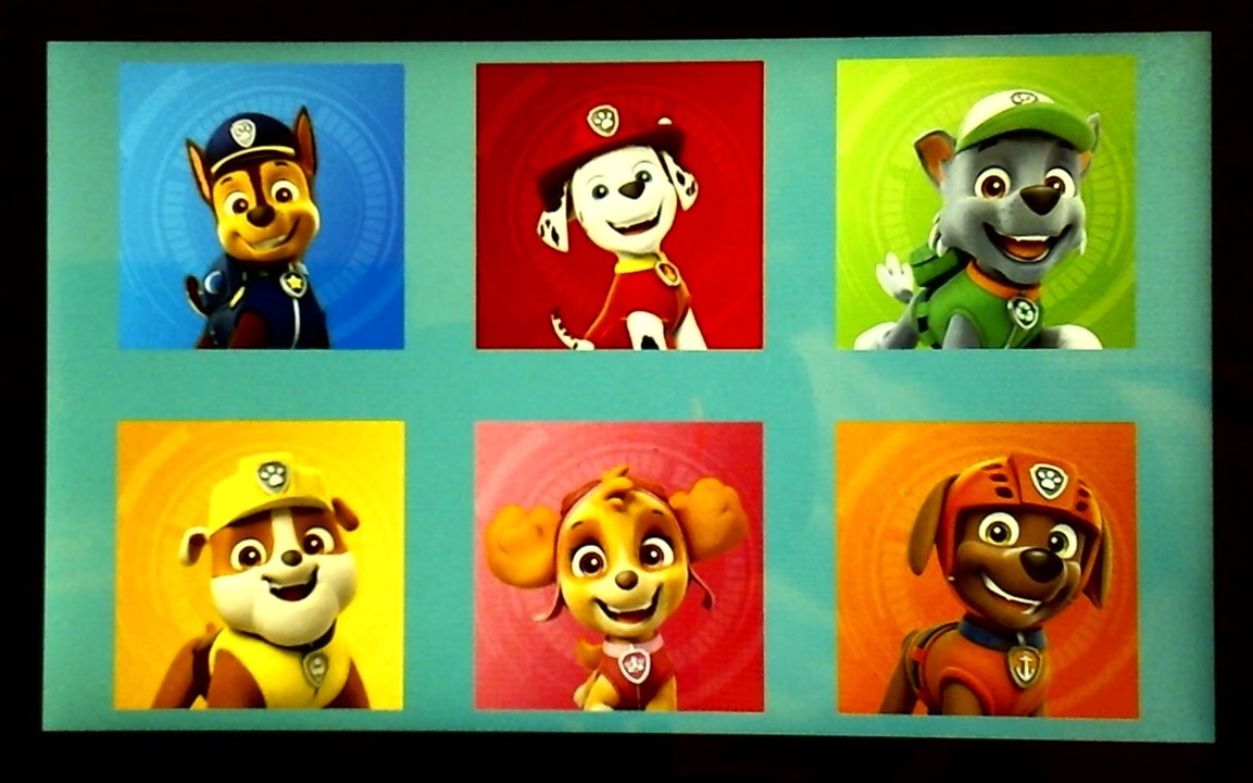
GigaDisplay_ImageGrid.ino
#include <Arduino_USBHostMbed5.h>
#include <DigitalOut.h>
#include <FATFileSystem.h>
#include <Arduino_H7_Video.h>
#include <Arduino_GigaDisplay_GFX.h>
#include <Arduino_GigaDisplayTouch.h>

Arduino_H7_Video Display;
GigaDisplay_GFX gfx;
Arduino_GigaDisplayTouch Touch;
USBHostMSD msd;
mbed::FATFileSystem usb("GIGA");

const int USB_HOST_ENABLE_PIN = PA_15;
const int MAX_FILES = 50;
const int MAX_NAME_LEN = 128;
char fileNames[MAX_FILES][MAX_NAME_LEN];
int fileCount = 0;
const int MAX_CONNECTION_ATTEMPTS = 10;

bool touchDown = false;

struct ImageCell {
    const char* path;
    int16_t x1, y1, x2, y2;
};

ImageCell cells[6] = {
    { "/GIGA/Chase200x200.bin", 50, 15, 200, 200 },
    { "/GIGA/Marshall200x200.bin", 300, 15, 200, 200 },
    { "/GIGA/Rocky200x200.bin", 550, 15, 200, 200 },
    { "/GIGA/Rubble200x200.bin", 50, 265, 200, 200 },
    { "/GIGA/Skye200x200.bin", 300, 265, 200, 200 },
    { "/GIGA/Zuma200x200.bin", 550, 265, 200, 200 }
};

void drawImage(const char *path, int16_t x, int16_t y, int16_t w, int16_t h);
void triggerAction(int index);

// -----------------
// Helper functions
// -----------------
bool initUSBHost() {
    for (int i = 0; i < MAX_CONNECTION_ATTEMPTS; i++) {
        if (msd.connect()) {
            Serial.println("USB mass storage device connected!");
            return true;
        }
        Serial.println("USB device not detected, retrying...");
        delay(1000);
    }
    return false;
}

bool mountUSB() {
    Serial.print("Mounting USB device... ");
    if (usb.mount(&msd)) {
        Serial.println("Failed to mount USB.");
        return false;
    }
    Serial.println("done.");
    return true;
}

void SerialPrintf(const char *fmt, ...) {
  char buf[128];
  va_list args;
  va_start(args, fmt);
  vsnprintf(buf, sizeof(buf), fmt, args);
  va_end(args);
  Serial.print(buf);
}


void setup() {
    Serial.begin(115200);
    while (!Serial) {}

    Display.begin();
    gfx.begin();  // initialize GFX layer
    Touch.begin();

     /* Enable power for HOST USB connector. */
    pinMode(PA_15, OUTPUT);
    digitalWrite(PA_15, HIGH);

    if (!initUSBHost() || !mountUSB()) return;

    gfx.setRotation(1);
    //gfx.fillScreen(0x0000); // clear to black
    gfx.fillScreen(0x5555);

    // Draw thumbnails
    for (int i = 0; i < 6; i++) {
        // drawImage(cells[i].path, cells[i].x1, cells[i].y1, cells[i].x2 - cells[i].x1, cells[i].y2 - cells[i].y1);
        drawImage(cells[i].path, cells[i].x1, cells[i].y1, cells[i].x2, cells[i].y2);
    }
}

void loop() {
    GDTpoint_t points[5];
    uint8_t contacts = Touch.getTouchPoints(points);

    if (contacts > 0) {
        int16_t tx = points[0].y;
        int16_t ty = 480 - points[0].x;

        if (!touchDown) {
            for (int i = 0; i < 6; i++) {
                if (tx >= cells[i].x1 && tx <= (cells[i].x1 + cells[i].x2) &&
                    ty >= cells[i].y1 && ty <= (cells[i].y1 + cells[i].y2)) {
                    SerialPrintf("Touched image %d\n", i + 1);
                    triggerAction(i);
//                    delay(100);
                    touchDown = true;
                    break;
                }
            }
        }
    } else {
        touchDown = false;
    }
}


void drawImage(const char *path, int16_t x, int16_t y, int16_t w, int16_t h) {
    FILE *f = fopen(path, "rb");
    if (!f) {
        SerialPrintf("Failed to open %s\n", path);
        return;
    }

    fseek(f, 4, SEEK_SET);  // skip 4-byte header

    static uint16_t rowBuf[480];  // width ≤ display width

    for (int row = 0; row < h; row++) {
        size_t readCount = fread(rowBuf, sizeof(uint16_t), w, f);
        if (readCount != w) break;
        gfx.drawRGBBitmap(x, y + row, rowBuf, w, 1);
    }

    fclose(f);
}


void triggerAction(int index) {
    switch(index) {
        case 0: Serial.println("Action 1 triggered"); delay(200); break;
        case 1: Serial.println("Action 2 triggered"); delay(200); break;
        case 2: Serial.println("Action 3 triggered"); delay(200); break;
        case 3: Serial.println("Action 4 triggered"); delay(200); break;
        case 4: Serial.println("Action 5 triggered"); delay(200); break;
        case 5: Serial.println("Action 6 triggered"); delay(200); break;
    }
}
Video showing a unique response on the Serial Monitor for each character touched.
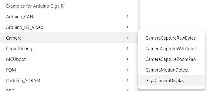
The Camera Tutorial points to the GigaCameraDisplay example that is included with the mbed_giga board package.
The Giga R1 is compatible with four DVP cameras from Arducam
For this roadtest I am using the OV7675 which has a resolution of 640x480 so it's a nice fit for the 800x480 display.
The camera initialization and operation uses the arducam_dvp library.
The example program provided some insight into some of the camera limitations. The example captures a 320x240 image and rotates it and scales it to 640x480 for display. It seemed odd that it would not just capture a 640x480 image directly. The rotation is necessary due to the orientation of the camera mounting on the display. It appears that the framebuffer is being captured into the internal 1MB SRAM for speed (framerate) purposes, so that would restrict the size to 320x240. The transformed display buffer is stored in the external SDRAM, so it can handle the larger image size. The camera framebuffer could have been captured into SDRAM, but it would still have had to be transformed for display. The other interesting thing was there was also another transformation for the color cameras. There was an HTONS operation on each value. In the program: #define HTONS(x) (((x >> 8) & 0x00FF) | ((x << 8) & 0xFF00)) which is a byte swap. So, the MCU which is capturing the framebuffer is operating in little endian format but the display requires big endian format. The grayscale cameras are only using a single byte so they don't require a swap.
Doug found that when he ran the example program that the image displayed on his screen was vertically flipped and horizontally mirrored, so he modified the mapping indexes in the transform routine to fix it. I decided that I would use his code to verify my setup was working and I found that I needed the vertical flip but not the horizontal mirror, so I only modified one of the indexes. It might be a difference between our cameras as he is using the GC2145 and I am using the OV7675.
I thought that most camera libraries have functions for vflip and hmirror and a quick look at the arducam_dvp.h file showed there are functions indeed defined.

And it does compile but the linker fails:

Another quick check of the arducam_dvp.cpp file showed that it did not have the functions implemented.
I went to the Arducam github repo and saw that there has only been one release of this library and that it was over 2 years ago. It seems that this library was never completed and it doesn't seem to be actively supported. I filed an issue but there hasn't been any response. I use quite a few Arducam cameras, so this was quite disappointing.
Here is my version of the example program using the vflip part of Doug's modification.
GigaCameraDisplay_DW.ino
#include "arducam_dvp.h"
#include "Arduino_H7_Video.h"
#include "dsi.h"
#include "SDRAM.h"

// This example only works with Greyscale cameras (due to the palette + resize&rotate algo)
#define ARDUCAM_CAMERA_OV767X

#ifdef ARDUCAM_CAMERA_HM01B0
#include "Himax_HM01B0/himax.h"
HM01B0 himax;
Camera cam(himax);
#define IMAGE_MODE CAMERA_GRAYSCALE
#elif defined(ARDUCAM_CAMERA_HM0360)
#include "Himax_HM0360/hm0360.h"
HM0360 himax;
Camera cam(himax);
#define IMAGE_MODE CAMERA_GRAYSCALE
#elif defined(ARDUCAM_CAMERA_OV767X)
#include "OV7670/ov767x.h"
// OV7670 ov767x;
OV7675 ov767x;
Camera cam(ov767x);
#define IMAGE_MODE CAMERA_RGB565
#elif defined(ARDUCAM_CAMERA_GC2145)
#include "GC2145/gc2145.h"
GC2145 galaxyCore;
Camera cam(galaxyCore);
#define IMAGE_MODE CAMERA_RGB565
#endif

// The buffer used to capture the frame
FrameBuffer fb;
// The buffer used to rotate and resize the frame
FrameBuffer outfb;

Arduino_H7_Video Display(800, 480, GigaDisplayShield);

void blinkLED(uint32_t count = 0xFFFFFFFF)
{
  pinMode(LED_BUILTIN, OUTPUT);
  while (count--) {
    digitalWrite(LED_BUILTIN, LOW);  // turn the LED on (HIGH is the voltage level)
    delay(50);                       // wait for a second
    digitalWrite(LED_BUILTIN, HIGH); // turn the LED off by making the voltage LOW
    delay(50);                       // wait for a second
  }
}

uint32_t palette[256];

void setup() {
  Serial.begin(115200);
  delay(5000);
  Serial.println("Serial okay!");

  // Init the cam QVGA, 30FPS
  if (!cam.begin(CAMERA_R320x240, IMAGE_MODE, 30)) {
    blinkLED();
  }

  //cam.setVerticalFlip(true);

  // Setup the palette to convert 8 bit greyscale to 32bit greyscale
  for (int i = 0; i < 256; i++) {
    palette[i] = 0xFF000000 | (i << 16) | (i << 8) | i;
  }

  Display.begin();


  if (IMAGE_MODE == CAMERA_GRAYSCALE) {
    dsi_configueCLUT((uint32_t*)palette);
  }
  outfb.setBuffer((uint8_t*)SDRAM.malloc(1024 * 1024));

  // clear the display (gives a nice black background)
  dsi_lcdClear(0x9ea69e);
  dsi_drawCurrentFrameBuffer();
  dsi_lcdClear(0x9ea69e);
  dsi_drawCurrentFrameBuffer();
}

#define HTONS(x)    (((x >> 8) & 0x00FF) | ((x << 8) & 0xFF00))

void loop() {

  // Grab frame and write to another framebuffer
  if (cam.grabFrame(fb, 3000) == 0) {

    // double the resolution and transpose (rotate by 90 degrees) in the same step
    // this only works if the camera feed is 320x240 and the area where we want to display is 640x480
    for (int i = 0; i < 320; i++) {
      int k = 320 - i;
      for (int j = 0; j < 240; j++) {
        int l = 240 - j;
        if (IMAGE_MODE == CAMERA_GRAYSCALE) {
          ((uint8_t*)outfb.getBuffer())[j * 2 + (i * 2) * 480] = ((uint8_t*)fb.getBuffer())[i + j * 320];
          ((uint8_t*)outfb.getBuffer())[j * 2 + (i * 2) * 480 + 1] = ((uint8_t*)fb.getBuffer())[i + j * 320];
          ((uint8_t*)outfb.getBuffer())[j * 2 + (i * 2 + 1) * 480] = ((uint8_t*)fb.getBuffer())[i + j * 320];
          ((uint8_t*)outfb.getBuffer())[j * 2 + (i * 2 + 1) * 480 + 1] = ((uint8_t*)fb.getBuffer())[i + j * 320];
        } else {
          ((uint16_t*)outfb.getBuffer())[l * 2 + (i * 2) * 480] = HTONS(((uint16_t*)fb.getBuffer())[i + j * 320]);
          ((uint16_t*)outfb.getBuffer())[l * 2 + (i * 2) * 480 + 1] = HTONS(((uint16_t*)fb.getBuffer())[i + j * 320]);
          ((uint16_t*)outfb.getBuffer())[l * 2 + (i * 2 + 1) * 480] = HTONS(((uint16_t*)fb.getBuffer())[i + j * 320]);
          ((uint16_t*)outfb.getBuffer())[l * 2 + (i * 2 + 1) * 480 + 1] = HTONS(((uint16_t*)fb.getBuffer())[i + j * 320]);
        }
      }
    }
    dsi_lcdDrawImage((void*)outfb.getBuffer(), (void*)dsi_getCurrentFrameBuffer(), 480, 640, IMAGE_MODE == CAMERA_GRAYSCALE ? DMA2D_INPUT_L8 : DMA2D_INPUT_RGB565);
    dsi_drawCurrentFrameBuffer();
  } else {
    blinkLED(20);
  }
}
I apologize for the poor video quality. I don't have a proper setup to be able to capture video from displays and the reflection from the glossy display screen also causes issues. My iPhone can capture somewhat better images, but for general video documentation I use a webcam as it is easier to process. Unfortunately, the webcam really struggles with the capturing the display with my office lighting. To reduce capturing my reflection on the screen I have to angle the screen and the webcam, hence the keystoning effects
Here is an image from my iPhone which still does not look as good clear as the display as I see it. The colors are also somewhat washed out.
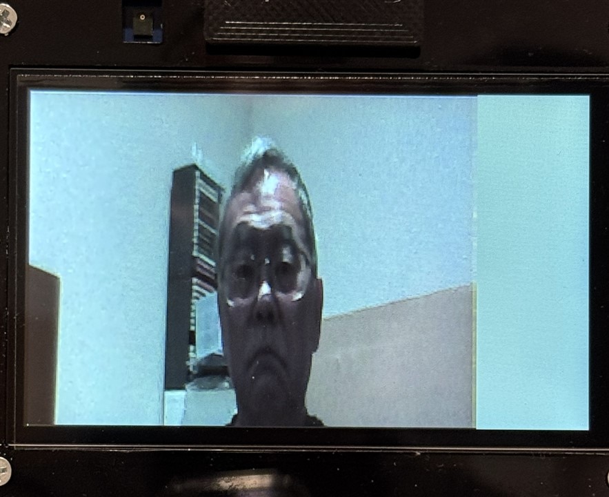
And here is a short video. I stood up so that you could see the lettering on my t-shirt to show that I did not need mirroring.
I wanted to try capturing the camera frame buffer in SDRAM, so that I could capture the 640x480 resolution of my camera. I decided that I would use the CameraCaptureWebserial example and modify it to use the SDRAM for the framebuffer. This example allows streaming the camera over USB Serial to a web browser application for display.
GigaCameraCaptureWebSerial.ino
/*
 * This example shows how to capture images from the camera and send them over Web Serial.
 *
 * There is a companion web app that receives the images and displays them in a canvas.
 * It can be found in the "extras" folder of this library.
 * The on-board LED lights up while the image is being sent over serial.
 *
 * Instructions:
 * 1. Make sure the correct camera is selected in the #include section below by uncommenting the correct line.
 * 2. Upload this sketch to your camera-equipped board.
 * 3. Open the web app in a browser (Chrome or Edge) by opening the index.html file
 * in the "WebSerialCamera" folder which is located in the "extras" folder.
 *
 * Initial author: Sebastian Romero @sebromero
 */

#include "camera.h"
#include "SDRAM.h"

#define ARDUCAM_CAMERA_OV767X

#ifdef ARDUINO_NICLA_VISION
  #include "gc2145.h"
  GC2145 galaxyCore;
  Camera cam(galaxyCore);
  #define IMAGE_MODE CAMERA_RGB565
#elif defined(ARDUINO_PORTENTA_H7_M7)
  // uncomment the correct camera in use
  #include "hm0360.h"
  HM0360 himax;
  // #include "himax.h";
  // HM01B0 himax;
  Camera cam(himax);
  #define IMAGE_MODE CAMERA_GRAYSCALE
#elif defined(ARDUINO_GIGA)
  #include "ov767x.h"
  // uncomment the correct camera in use
  OV7670 ov767x;
  // OV7675 ov767x;
  Camera cam(ov767x);
  #define IMAGE_MODE CAMERA_RGB565
#else
#error "This board is unsupported."
#endif

/*
Other buffer instantiation options:
  FrameBuffer fb(0x30000000);
  FrameBuffer fb(320,240,2);

If resolution higher than 320x240 is required, please use external RAM via
  #include "SDRAM.h"
  FrameBuffer fb(SDRAM_START_ADDRESS);
  ...
  // and adding in setup()
  SDRAM.begin();
*/
constexpr uint16_t CHUNK_SIZE = 512;  // Size of chunks in bytes
//constexpr uint8_t RESOLUTION  = CAMERA_R320x240; // CAMERA_R160x120
constexpr uint8_t RESOLUTION  = CAMERA_R640x480;
constexpr uint8_t CONFIG_SEND_REQUEST = 2;
constexpr uint8_t IMAGE_SEND_REQUEST = 1;

uint8_t START_SEQUENCE[4] = { 0xfa, 0xce, 0xfe, 0xed };
uint8_t STOP_SEQUENCE[4] = { 0xda, 0xbb, 0xad, 0x00 };
//FrameBuffer fb;
FrameBuffer fb(SDRAM_START_ADDRESS);

/**
 * Blinks the LED a specified number of times.
 * @param ledPin The pin number of the LED.
 * @param count The number of times to blink the LED. Default is 0xFFFFFFFF.
 */
void blinkLED(int ledPin, uint32_t count = 0xFFFFFFFF) {
  while (count--) {
    digitalWrite(ledPin, LOW);  // turn the LED on (HIGH is the voltage level)
    delay(50);                       // wait for a second
    digitalWrite(ledPin, HIGH); // turn the LED off by making the voltage LOW
    delay(50);                       // wait for a second
  }
}

void setup() {
  pinMode(LED_BUILTIN, OUTPUT);
  pinMode(LEDR, OUTPUT);
  digitalWrite(LED_BUILTIN, HIGH);
  digitalWrite(LEDR, HIGH);
  // Serial.begin(115200);
  // delay(2000);

  SDRAM.begin();

  // Init the cam VGA, 15FPS
  if (!cam.begin(RESOLUTION, IMAGE_MODE, 15)) {
    Serial.println("Camera init failed");
    while (1);
    blinkLED(LEDR);
  }

  // debug: check where your frame buffer pointer is
  uint8_t *ptr = fb.getBuffer();
  Serial.print("User FrameBuffer pointer: 0x");
  Serial.println((uintptr_t)ptr, HEX);
  Serial.print("Framebuffer size: ");
  Serial.println(fb.getBufferSize());
  Serial.print("Frame size expected: ");
  Serial.println(cam.frameSize());

  // Capture into the SDRAM-backed framebuffer
  int rc = cam.grabFrame(fb, 5000);
  if (rc != 0) {
    Serial.print("grabFrame failed: ");
    Serial.println(rc);
    delay(1000);
    return;
  }

  // fb.getBuffer() now points to the image data in SDRAM
  uint8_t *image = fb.getBuffer();
  int sz = cam.frameSize(); // bytes

  // Example: print first 16 bytes for quick verify
  for (int i = 0; i < 16 && i < sz; ++i) {
    if (i) Serial.print(' ');
    Serial.print(image[i], HEX);
  }
  Serial.println();

  blinkLED(LED_BUILTIN, 5);
}

/**
 * Sends a chunk of data over a serial connection.
 *
 * @param buffer The buffer containing the data to be sent.
 * @param bufferSize The size of the buffer.
 */
void sendChunk(uint8_t* buffer, size_t bufferSize){
  Serial.write(buffer, bufferSize);
  Serial.flush();
  delay(1); // Optional: Add a small delay to allow the receiver to process the chunk
}

/**
 * Sends a frame of camera image data over a serial connection.
 */
void sendFrame(){
  // Grab frame and write to serial
  if (cam.grabFrame(fb, 3000) == 0) {
    byte* buffer = fb.getBuffer();
    size_t bufferSize = cam.frameSize();
    digitalWrite(LED_BUILTIN, LOW);

    sendChunk(START_SEQUENCE, sizeof(START_SEQUENCE));

    // Split buffer into chunks
    for(size_t i = 0; i < bufferSize; i += CHUNK_SIZE) {
      size_t chunkSize = min(bufferSize - i, CHUNK_SIZE);
      sendChunk(buffer + i, chunkSize);
    }

    sendChunk(STOP_SEQUENCE, sizeof(STOP_SEQUENCE));

    digitalWrite(LED_BUILTIN, HIGH);
  } else {
    blinkLED(20);
  }
}

/**
 * Sends the camera configuration over a serial connection.
 * This is used to configure the web app to display the image correctly.
 */
void sendCameraConfig(){
  Serial.write(IMAGE_MODE);
  Serial.write(RESOLUTION);
  Serial.flush();
  delay(1);
}

void loop() {
  if(!Serial) {
    Serial.begin(115200);
    while(!Serial);
  }

  if(!Serial.available()) return;

  byte request = Serial.read();

  switch(request){
    case IMAGE_SEND_REQUEST:
      sendFrame();
      break;
    case CONFIG_SEND_REQUEST:
      sendCameraConfig();
      break;
  }

  //delay(100); // whatever capture cadence you want

}
The video capture of my browser screen. There is noticeable lag running 640x480 over serial.
I did try allocating SDRAM for both the camera framebuffer and the display buffer in the first GigaCameraDisplay example, but I didn't get that to work. I used the rotation and HTON transformation without scaling. No compilation issues, just didn't get anything displayed. That should work, so I'll go back and debug it when I have more time.
Audio output
The Giga R1 has 2 DACs and the Display Shield has a PDM microphone. These are brought out an audio jack and the analog header.

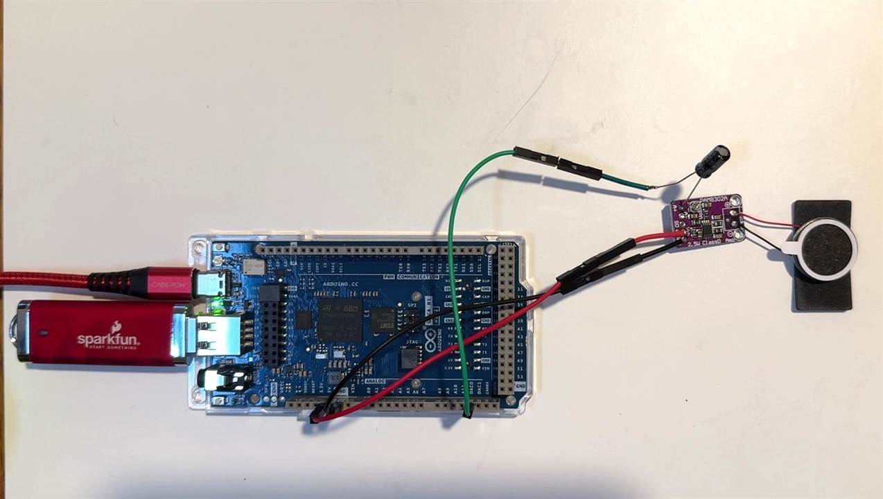
I tried using headphones in the audio jack and that works with low sound volume, but for my application I would need an external speaker and audio amplifier. I could have used an I2S amplifier, but for simplicity and ease of implementation I chose to use a mono PAM8302 analog amplifier board that I drove from the DAC0 pin on the analog header.
Here is a pic of my initial test setup:
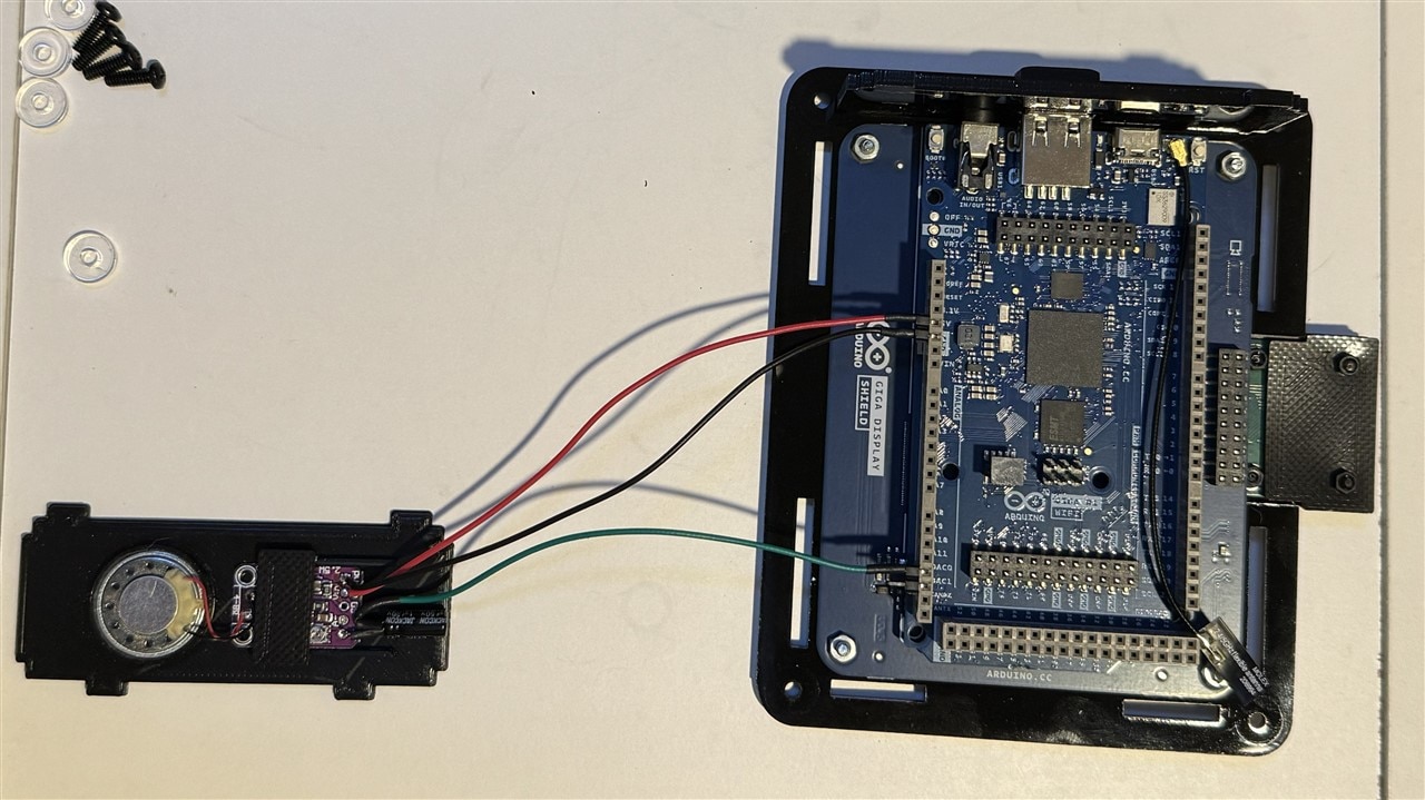
The good news is the ProtoStax case has removeable side panels, so I printed a new side panel to mount the PAM8302 board and mini speaker.
The audio files used for the examples are 16-bit PCM WAV files (stereo or mono). Files are generally stored and accessed from a FAT32 formatted USB drive. The files that I am using were found on the free database at 101 Soundboards. They have quite a few AI generated voice clips for the PAW Patrol characters.
I'll have to buy Doug a coffee sometime because since he did modify one of the AdvancedAnalog examples that utilized the DAC with the Display and USB storage, so that was a good place to start again (at least I knew that would work).
GigaR1_WavPlayer_DW.ino
/*
 * GIGA WAV Player
 * GIGA R1 - Audio Playback of a wav file store on a USB memory device
 * Simple wav format audio playback via 12-Bit DAC output by reading from a USB drive.
 * This sketch assumes the USB memory device is named "USB"
 * This sketch assumes the audio file is named "GIGAchorus.wav"
 * by Doug Wong 2025
*/

#include <Arduino_AdvancedAnalog.h>
#include <DigitalOut.h>
#include <Arduino_USBHostMbed5.h>
#include <FATFileSystem.h>
#include "Arduino_GigaDisplay_GFX.h"

#define WHITE 0xffff
#define BLACK 0x0000
#define YELLOW 0xFFE0
#define CYAN 0x07FFF
#define PURPLE 0x8010

AdvancedDAC dac0(A12);

USBHostMSD msd;
mbed::FATFileSystem usb("usb");

GigaDisplay_GFX display;

FILE * file = nullptr;
int sample_size = 0;
int samples_count = 0;


void setup()
{
  Serial.begin(115200);
  while (!Serial);

  display.begin();
  display.setRotation(1); // Landscape mode
  display.fillScreen(PURPLE);
  display.setTextColor(YELLOW);
  display.setTextSize(8);
  display.setCursor(35, 200);
  display.println("GIGA WAV Player");
  delay(4000);
  display.fillScreen(PURPLE);
  display.setTextSize(4);
  display.setCursor(10, 10);
  display.println("Reading USB...");

  /* Enable power for HOST USB connector. */
  pinMode(PA_15, OUTPUT);
  digitalWrite(PA_15, HIGH);

  if (!msd.connect()) {
    display.println("Insert USB memory device");
    while (!msd.connect()) delay(100);
  }
  display.println("Mounting USB...");
  int const rc_mount = usb.mount(&msd);
  if (rc_mount)
  {
    display.println("Error mounting USB device ");
    display.println(rc_mount);
    return;
  }

  display.println("Opening audio file ...");

  /* 16-bit PCM Mono 16kHz realigned noise reduction */
  file = fopen("/usb/we-wish-you-a-merry-christmas-loud.wav", "rb");
  if (file == nullptr)
  {
    display.print("Error opening audio file: ");
    display.println(strerror(errno));
    return;
  }

  display.println("Reading audio header ...");

  delay(200);
  display.fillScreen(PURPLE);
  display.setTextSize(3);
  display.setCursor(10, 1);

  struct wav_header_t
  {
    char chunkID[4]; //"RIFF" = 0x46464952
    unsigned long chunkSize; //28 [+ sizeof(wExtraFormatBytes) + wExtraFormatBytes] + sum(sizeof(chunk.id) + sizeof(chunk.size) + chunk.size)
    char format[4]; //"WAVE" = 0x45564157
    char subchunk1ID[4]; //"fmt " = 0x20746D66
    unsigned long subchunk1Size; //16 [+ sizeof(wExtraFormatBytes) + wExtraFormatBytes]
    unsigned short audioFormat;
    unsigned short numChannels;
    unsigned long sampleRate;
    unsigned long byteRate;
    unsigned short blockAlign;
    unsigned short bitsPerSample;
  };

  wav_header_t header;
  fread(&header, sizeof(header), 1, file);

  display.println("WAV File Header read:");
  char msg[64] = {0};
  snprintf(msg, sizeof(msg), "File Type: %s", header.chunkID);
  display.println(msg);
  snprintf(msg, sizeof(msg), "File Size: %ld", header.chunkSize);
  display.println(msg);
  snprintf(msg, sizeof(msg), "WAV Marker: %s", header.format);
  display.println(msg);
  snprintf(msg, sizeof(msg), "Format Name: %s", header.subchunk1ID);
  display.println(msg);
  snprintf(msg, sizeof(msg), "Format Length: %ld", header.subchunk1Size);
  display.println(msg);
  snprintf(msg, sizeof(msg), "Format Type: %hd", header.audioFormat);
  display.println(msg);
  snprintf(msg, sizeof(msg), "Number of Channels: %hd", header.numChannels);
  display.println(msg);
  snprintf(msg, sizeof(msg), "Sample Rate: %ld", header.sampleRate);
  display.println(msg);
  snprintf(msg, sizeof(msg), "Sample Rate * Bits/Sample * Channels / 8: %ld", header.byteRate);
  display.println(msg);
  snprintf(msg, sizeof(msg), "Bits per Sample * Channels / 8: %hd", header.blockAlign);
  display.println(msg);
  snprintf(msg, sizeof(msg), "Bits per Sample: %hd", header.bitsPerSample);
  display.println(msg);

  /* Find the data section of the WAV file. */
  struct chunk_t
  {
    char ID[4];
    unsigned long size;
  };

  chunk_t chunk;
  snprintf(msg, sizeof(msg), "id\t" "size");
  display.println(msg);
  /* Find data chunk. */
  while (true)
  {
    fread(&chunk, sizeof(chunk), 1, file);
    snprintf(msg, sizeof(msg), "%c%c%c%c\t" "%li", chunk.ID[0], chunk.ID[1], chunk.ID[2], chunk.ID[3], chunk.size);
    display.println(msg);
    if (*(unsigned int *) &chunk.ID == 0x61746164)
      break;
    /* Skip chunk data bytes. */
    fseek(file, chunk.size, SEEK_CUR);
  }

  /* Determine number of samples. */
  sample_size = header.bitsPerSample / 8;
  samples_count = chunk.size * 8 / header.bitsPerSample;
  snprintf(msg, sizeof(msg), "Sample size = %i", sample_size); display.println(msg);
  snprintf(msg, sizeof(msg), "Samples count = %i", samples_count); display.println(msg);

  /* Configure the advanced DAC. */
  if (!dac0.begin(AN_RESOLUTION_12, header.sampleRate * 2, 256, 16))
  {
    display.println("Failed to start DAC1 !");
    return;
  }

  delay(1500);
  display.fillScreen(PURPLE);
  display.setCursor(50, 50);
  display.setTextSize(4);
  display.println("Playing ......");
  display.setCursor(50, 200);
  display.setTextSize(3);
  display.println("we-wish-you-a-merry-christmas.WAV");
}

void loop()
{
  if (dac0.available() && !feof(file))
  {
    /* Read data from file. */
    uint16_t sample_data[256] = {0};
    fread(sample_data, sample_size, 256, file);

    /* Get a free buffer for writing. */
    SampleBuffer buf = dac0.dequeue();

    /* Write data to buffer. */
    for (size_t i = 0; i < buf.size(); i++)
    {
      /* Scale down to 12 bit. */
      uint16_t const dac_val = ((static_cast<unsigned int>(sample_data[i])+32768)>>4) & 0x0fff;
      buf[i] = dac_val;
    }

    /* Write the buffer to DAC. */
    dac0.write(buf);
  }
}
One thing that somewhat surprised me was how much code was required play the WAV file. Surprised in the sense that generally a library would handle that low level code and provide functions to accomplish that task. I found that in the GigaAudio library that there was an example that did that.

As a matter of there is an incredible amount of integration in that library. It looks like Arduino went to great lengths to simplify the Giga audio interface. I was really surprised that the connecting and mounting of the USB drive was handled automagically. There were 4 lines of code that did what was required to play the WAV file from the USB drive!
#include <GigaAudio.h>
GigaAudio audio("GIGA"); // replace with name of USB volume
audio.load("chase.wav");
audio.play();
GigaR1_PlaySingleFile.ino
/**
 * Plays a single audio file on an attached USB dive
 */
#include <GigaAudio.h>
#include "Arduino_GigaDisplay_GFX.h"

GigaAudio audio("GIGA"); // replace with name of USB volume
GigaDisplay_GFX display;

void setup() {
    pinMode(PA_15, OUTPUT);
    digitalWrite(PA_15, HIGH);

    Serial.begin(115200);
    delay(2000);

    display.begin();
    display.setRotation(1); // Landscape mode

    display.fillScreen(0x5555);
    display.setTextColor(0xffff); //White
    display.setTextSize(8);
    display.setCursor(150, 200);
    display.println("Paw Patrol");

    if (!audio.load("chase.wav")) {  // replace with name of file to play
        if (audio.hasError()) Serial.println(audio.errorMessage());
        else Serial.println("Cannot load WAV file");
        return;
    }

    delay(3000);
    display.fillScreen(0x5555);
    display.setCursor(80, 100);
    display.setTextSize(6);
    display.println("Playing:");
    display.setCursor(100, 200);
    display.setTextSize(5);
    display.println("chase.wav");

}

int repeat = 0;

void loop() {

    if (audio.isFinished() && repeat < 1) {
        delay(5000);
        audio.play(); // restart the playback when it is complete
        Serial.println("Restarting . . .");
        repeat++;
    }
}
At this point it appeared that it might be easy be to combine audio and the GUI. I just had to verify that I could access the USB drive that GigaAudio had mounted. Unfortunately, I could not figure out how to access the drive using the standard commands (fopen, fread) that are use by USBHostMSD and the FATFileSystem interfaces. I could not even get it to show me what the mount point was. It won't be helpful if I can't access the drive for image files.
I then discovered that the AdvancedAnalog library had a WavReader class and an example that used it.

WavReader.h
/*
  This file is part of the Arduino_AdvancedAnalog library.
  Copyright (c) 2024 Arduino SA. All rights reserved.

  This library is free software; you can redistribute it and/or
  modify it under the terms of the GNU Lesser General Public
  License as published by the Free Software Foundation; either
  version 2.1 of the License, or (at your option) any later version.

  This library is distributed in the hope that it will be useful,
  but WITHOUT ANY WARRANTY; without even the implied warranty of
  MERCHANTABILITY or FITNESS FOR A PARTICULAR PURPOSE.  See the GNU
  Lesser General Public License for more details.

  You should have received a copy of the GNU Lesser General Public
  License along with this library; if not, write to the Free Software
  Foundation, Inc., 51 Franklin Street, Fifth Floor, Boston, MA  02110-1301  USA
*/

#ifndef __ADVANCED_WAV_READER_H__
#define __ADVANCED_WAV_READER_H__

#include "AdvancedAnalog.h"

class WavReader {
    typedef struct {
        char chunk_id[4];
        unsigned int chunk_size;
        char format[4];
        char subchunk1_id[4];
        unsigned int subchunk1_size;
        unsigned short audio_format;
        unsigned short num_channels;
        unsigned int sample_rate;
        unsigned int byte_rate;
        unsigned short block_align;
        unsigned short bits_per_sample;
        char subchunk2_id[4];
        unsigned int subchunk2_size;
    } WavHeader;

    private:
        FILE *file;
        bool loop;
        WavHeader header;
        DMAPool<Sample> *pool;

    public:
        WavReader(): file(nullptr), loop(false), pool(nullptr) {
        }
        ~WavReader();
        size_t channels() {
            return header.num_channels;
        }

        size_t resolution() {
            return header.bits_per_sample;
        }

        size_t sample_rate() {
            return header.sample_rate;
        }

        size_t sample_count() {
            return (header.subchunk2_size * 8) / header.bits_per_sample;
        }

        int begin(const char *path, size_t n_samples, size_t n_buffers, bool loop=false);
        void stop();
        bool available();
        SampleBuffer read();
        int rewind();
};
#endif // __ADVANCED_WAV_READER_H__
That looked promising because that example used the USBHostMSD and FATFileSystem. Unfortunately, the drive would connect and mount but WavReader could not open the file - so the example did not work. It appears that there are version mismatches with the libraries that are causing problems.
The only workaround at this point is to use the low level code that is used in the example that Doug used.
Audio input
The Display Shield has a PDM microphone. The ProtoStax demo that I initially ran showed the microphone output in an LVGL chart, so I knew it was functioning. What I wanted to do is some basic keyword spotting so that I could use the audio input for control. My first step was to record some audio from the PDM microphone to a file on the USB drive and then use that as input to Edge Impulse to build a model. Unfortunately this failed miserably. I found that I could not use the PDM library with the USBHost library. Apparently this is a known issue with the Giga R1 and Display shield. There is conflict between the DFSDM peripheral and USBHostMSD. Since these are Mbed core libraries, my only real recourse is to use the latest Mbed library and I already am. So, this a showstopper for me relative to using the Display bundle in my application. The possible workarounds are using an external I2S microphone or an external analog microphone, or I could add an SD card instead of the USB drive for storage. Those alternatives are not something that I really want to do at this point due to time constraints (and I don't have the parts).
I've already demonstrated the USB connectivity with the Camera Web Serial example.
For WiFi I did a quick check of how well the WiFi RSSI was by using the ScanNetworkAdvanced example.
I have two access points upstairs in my office and one downstairs. I wanted to see how well the WiFi with the little flag antenna was doing in my house.
So, everything looks good. I had added the access point downstairs to get coverage in the backyard.
What I plan to use with the application is MQTT for messaging. I have an RPi4 that is dedicated for an MQTT Broker and Node-Red Server. I made a simple Node-Red Dashboard with two character buttons and one text box to receive messages from the Giga R1 for testing..
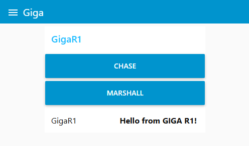
The test program is pretty simple.
I have 2 message topics:
Here is my Node-Red flow:
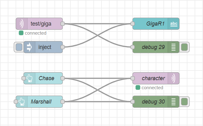
GigaR1_MQTT_Test.ino
#include <WiFi.h>
#include <PubSubClient.h>
#include "arduino_secrets.h"

// ---- EDIT THESE ----
const char* ssid     = SECRET_SSID;
const char* password = SECRET_PASS;

const char* mqttServer = "10.0.0.234";  // or your own broker
int mqttPort = 1883;

WiFiClient wifiClient;
PubSubClient client(wifiClient);

// Called when messages arrive on subscribed topics
void callback(char* topic, byte* payload, unsigned int length) {
  Serial.print("Message on topic ");
  Serial.print(topic);
  Serial.print(": ");

  for (int i = 0; i < length; i++)
    Serial.print((char)payload[i]);

  Serial.println();
}

void reconnect() {
  while (!client.connected()) {
    Serial.print("Connecting to MQTT...");
    if (client.connect("GIGA-R1-Client")) {
      Serial.println("Connected!");
      client.subscribe("test/giga");
      client.subscribe("ppc/character");
    } else {
      Serial.print(" Failed. State=");
      Serial.println(client.state());
      delay(2000);
    }
  }
}

void setup() {
  Serial.begin(115200);
  delay(2000);

  // WiFi
  Serial.print("Connecting to Wi-Fi");
  WiFi.begin(ssid, password);
  while (WiFi.status() != WL_CONNECTED) {
    delay(250);
    Serial.print(".");
  }
  Serial.println("\nWi-Fi connected!");

  // MQTT
  client.setServer(mqttServer, mqttPort);
  client.setCallback(callback);
}

void loop() {
  if (!client.connected()) reconnect();
  client.loop();

  // Publish a message every 5 seconds
  static unsigned long lastMsg = 0;
  if (millis() - lastMsg > 30000) {
    lastMsg = millis();
    client.publish("test/giga", "Hello from GIGA R1!");
  }
}
Video showing the Dashboard and the Serial Monitor showing the interaction of the MQTT messages.
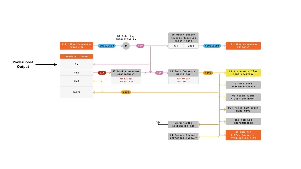
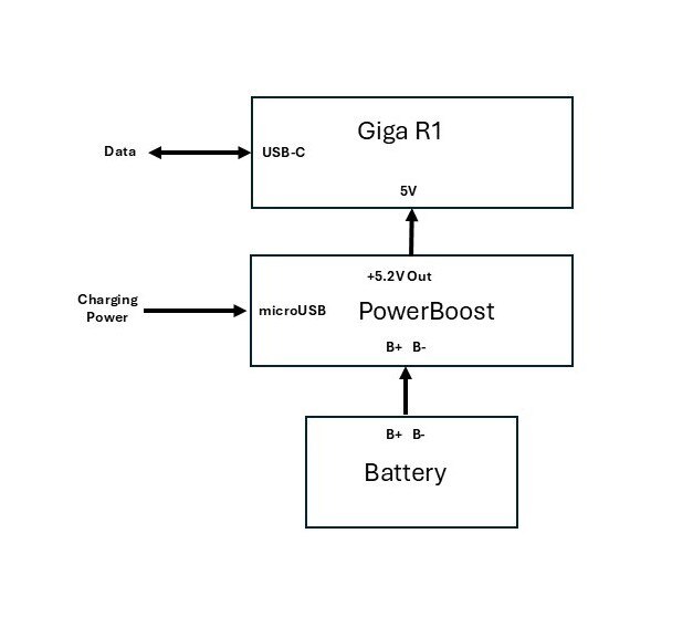
The Giga R1 does not have a battery interface, but I thought that I'd look into how difficult it would be to add one. The power consumption of the Giga R1 + Display Shield depends on the specific use case with the primary high power consumers being WiFi and the Display backlight. A reasonable estimate is 150mA for the Giga R1 and 250mA for the Display Shield, so a 1000mAH battery would provide 2+ hours of runtime. The simplest solution is to use a UPS type battery management device like the Adafruit PowerBoost 1000C. The PowerBoost provides battery management and charging plus an output boost circuit to +5.2V. There is no easy access to the USB-C VBUS on the Giga R1, so it seems the best solution is to have a separate independent charging source for the PowerBoost and use the USB-C for data only. The PowerBoost +5.2V output would tie to the Giga R1 5V pin on the Power header. Since the 5V net is after the Schottky diode from USB-C VBUS, the Giga R1 would always be powered by the PowerBoost unless the battery were depleted and there was no charging source then it would use the USB-C power if it were connected.
Here is the Giga R1 Power Tree
And a simple block diagram of the hookup (common ground between boards is assumed).
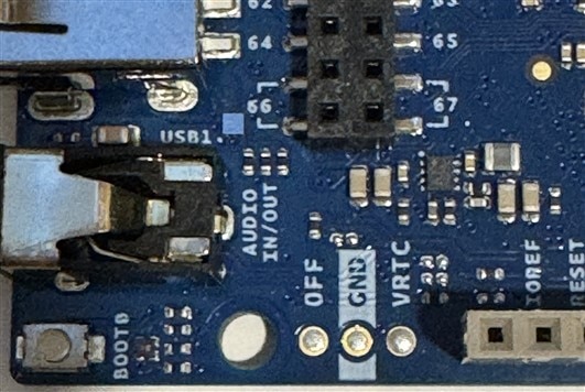
A feature that the Giga R1 has that is helpful for UPS operation is an "OFF" pin. Behind the Audio Output jack there is a spot for a 3 pin header for OFF and VRTC which is the backup battery input for the MCU RTC. The OFF pin connects to the Enable pin of the onboard +3.3V regulator and will shut it down when connected to GND. If power is still available to the board input, then the +3.3V will power up when the OFF pin is released.
I have lots of room in the ProtoStax case for a PowerBoost and a battery, but I would probably have to modify or print a new backplate and top plate to mount everything.
I wanted to demonstrate in this roadtest the user experience (of an experienced not expert user) in using the Arduino GigaDisplay Bundle hardware and software to develop a portable communicator application. I haven't had much problem with the hardware other than issues with the initial Giga R1 missing a connector and also that somewhere along the roadtest the IMU on the Display Shield stopped functioning. I am nowhere close to an actual application, but I think that I attempted enough of the necessary elements to get a good sense of the current state of the hardware and software development environment. It was not my intent to document all of the features or issues that I encountered, but I did want to show specific aspects to justify my roadtest scoring.
On the hardware side of things, the Giga Display Bundle has an incredible set of features. Some were missing relative to my intended application like an audio amplifier and battery support. And some I did not get around to test like the dual processor support, BLE, and the incredible set of GPIO pins and functions. There are a couple of physical changes that I'd like to see for future devices. The first is a less glossy display screen. I have a Unihiker K10 that has more of a matte finish on the screen and I like that it doesn't have the mirror-like quality of a high gloss screen. I did try an anti-glare screen protector, but that only helped a little. Secondly, I'd like to have board mounted pushbuttons (Reset, Boot) mounted at right angles to the PCB. This makes them easier to operate when the board is mounted in a case. I had to use the Reset button a lot during this roadtest. Luckily, I found that I could implement a side lever using an M4 screw and nut to depress the button.
The software was where I had most all of my problems in this roadtest. I anticipated that I would encounter version issues between the examples and the libraries and I certainly had enough of those. These are sort of par for the course due to software being under continuous development and no one seems to run regressions anymore. Somewhere along the line the core software switched from supporting LVGL version 8 to version 9. That caused issues with names and parameters of classes and class members and structs. These cause compilation errors, but are generally easy to find although you can spend a lot of time looking through .h files. The software libraries provided by Arduino reminded me of the saying "there is more than one way to skin a cat". I don't mind lots of libraries to do sort of the same thing if there is good API documentation and working examples.
The problem with the resource conflicts between the DFSDM peripheral and USBHostMSD was particularly nasty. I don't know the specific failure mechanism, but it would hang the USB port on my PC in addition to hanging the MCU. In troubleshooting what I thought was a problem in my code, I did quite a few power cycles on my PC as that was the only way to recover the USB port. If this is a known issue with the current software versions there should be a warning somewhere in the documentation.
I am not sure what happened to the IMU. It was functioning at the beginning of the roadtest. I ran an I2C scanner and it found the IMU on Wire1 at address 0x68. The IMU initializes okay and I can read the sample rates from both the gyro and accelerometer. Unfortunately, the gyroscopeAvailable() and accelerationAvailable() functions which indicate samples in the FIFO never return true. Not sure how to debug this. The sample rates are apparently not reasonable values (0.39 Hz). And trying to read acceleration values using direct I2C reads returns 0. I have tried reinstalling the library and that didn't work. Maybe it died. More investigation required.
The hardware has great potential once the software libraries get sorted out. Simple things like a consistent way to mount the USB drive. And examples known to work with the version of the libraries that they are included with. And hopefully a fix for the DFSDM/USBHost conflict.
I want to thank E14 for the opportunity to roadtest this hardware. When I get the integrated application running I'll post a follow-up blog.


