RoadTest: Test out Arduino's Uno Q - The new Single-Board Computer!
Author: taifur
Creation date:
Evaluation Type: Development Boards & Tools
Did you receive all parts the manufacturer stated would be included in the package?: True
What other parts do you consider comparable to this product?: Raspberry Pi, LattePanda, NVIDIA Jetson Orin Nano
What were the biggest problems encountered?: As this is a comparatively new board, software support is very limited. Very few example programs/projects are available. No official camera module is available till now. For connecting a USB web camera, a USB-C hub is required, which reduces the compactness of any project.
Detailed Review:
I started my embedded system journey in 2009 with the PIC microcontroller. The PIC16F877A was my first microcontroller, and I still love it because it was my first love in the world of MCUs. The journey was challenging because I had to build everything from scratch. I made my own serial programmer, spending countless hours troubleshooting and fixing errors. I learned every step through trial and error. I still remember the moment when I successfully uploaded my very first program to the PIC16F877A using my own programmer. It was just a tiny LED blinking program, but at that moment, it felt magical to me. At that moment, I felt like I had touched the sky. It was more than just running a program; it was the moment I truly fell in love with the world of microcontrollers and embedded systems.
After a few months, probably in early 2011, I was introduced to the Arduino UNO. Arduino was not very popular at that time, but it was just starting to gain attention and showed enormous potential. Arduino changed the way I looked at microcontrollers and made the learning journey incredibly easy. There was no need for an external programmer, no frustrating fuse settings, and no constant tension about the power supply. Arduino made everything feel simple and accessible. I made many interesting and fun projects using Arduino.
In 2012, Raspberry Pi officially entered the market and quickly became one of the most popular single-board computers among hobbyists and the maker community. Raspberry Pi made embedded and DIY computing accessible to everyone for just $35. But Raspberry Pi has some limitations. Since it runs a full-fledged operating system, it is not well-suited for real-time hardware control, as Linux introduces its own overhead and background tasks. Pi also lacks built-in analog-to-digital conversion (ADC) functionality.
If you want to build a complex embedded system that reads multiple analog sensors, drives motors in real time, and simultaneously performs heavy vision processing, neither Arduino nor Raspberry Pi alone can perfectly handle everything. The common solution is to use an Arduino for low-level real-time tasks like sensor reading and motor control, while the Raspberry Pi handles high-level processing such as computer vision and AI. The two boards then communicate through USB or UART, working together as a complete system. However, this setup can sometimes introduce communication stability issues because you are trying to connect two completely different architectures. It may also introduce timing mismatches, and even minor issues such as vibration or a loose serial cable can disrupt communication. To address all these challenges, the Arduino UNO Q came into the picture. The UNO Q integrated these two different architectures, the "acting brain" and the "thinking brain", onto a single PCB, and the two brains communicate with each other using RPC bridge.
The Arduino UNO Q comes with the traditional UNO form factor and features a modern USB-C connector instead of the USB Type-B port used in the traditional Arduino UNO. The pin headers are fully compatible with the classic Arduino UNO, while the board also includes an additional QWIIC connector and an onboard 8x13 LED matrix.

The top side of the board includes the main processor, LPDDR4 RAM, power management IC (PMIC), WiFi and BLE communication module, and USB-C bridge IC. The bottom side of the board includes the microcontroller and the eMMC storage IC. There are also two advanced expansion headers on the bottom side.

The image is taken from the official Arduino website.
A bit of hardware details:
Arduino offers RPC Bridge (Remote Procedure Call) for effortless communication between the MPU and MCU.
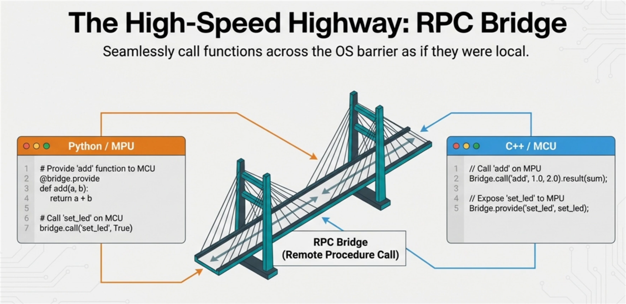
The image is taken from the YouTube video: https://www.youtube.com/watch?v=jr3KN-LEUUM&t=547s
Before connecting the UNO Q to my computer and getting my hands dirty, I wanted to take a look at the official Arduino Getting Started guide. So, I searched for “Arduino UNO Q” and found the official Arduino UNO Q page here. The official page includes all the necessary resources, including the pinout, schematics, CAD files, technical specifications, tutorials, and the recommended libraries.
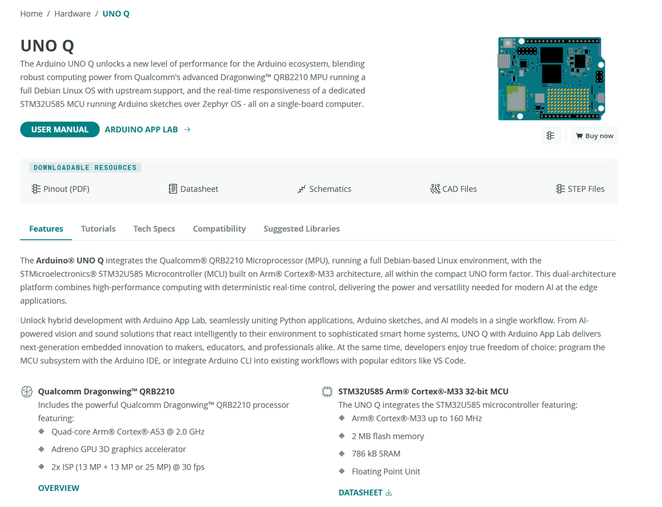
I was looking for the getting-started guide, so from the tutorials tab, I clicked on UNO Q User Manual, which includes all the necessary information for getting started. As per the user manual, the following hardware and software are required to get started with the board.
Thanks to Element14 and Arduino for sending all the hardware components as the Road Test kit. From the page, I learned that the Arduino UNO Q can be used in two different modes. One is the single-board computer mode, where I need to connect a mouse, keyboard, and monitor to the Arduino UNO Q using a USB-C multiport adapter. The other is the PC-hosted mode, where I simply need to connect the board to my PC using a USB-C cable. I am a bit lazy, so I decided to try the Arduino UNO Q in PC-hosted mode first to avoid connecting all the external peripherals. For the PC-hosted setup, the host PC needs to have the Arduino App Lab IDE installed. So, I downloaded the Arduino App Lab IDE from the link provided on the page and installed it on my Windows PC.
After installing the App Lab, I double-clicked on the App Lab desktop icon to run it and got the following message.
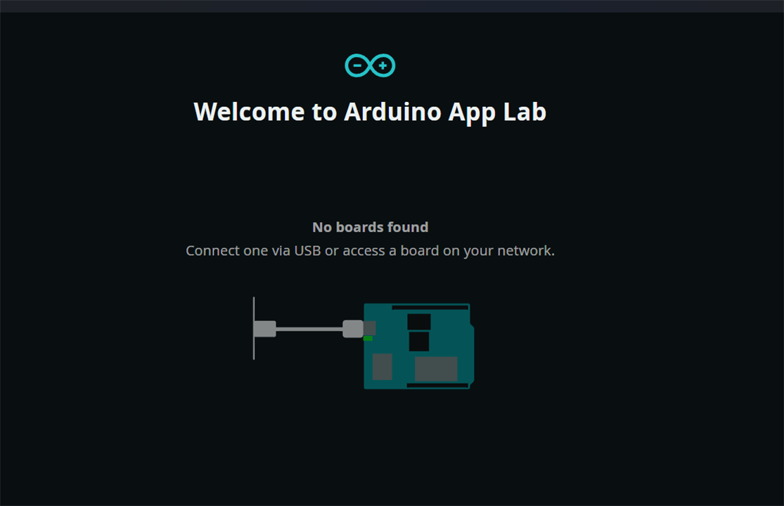
From the message, I realized that I needed to connect the Arduino UNO Q to my PC before running the App Lab. So, I connected the board using a USB-C cable and was greeted by a beautiful blue Arduino logo animation on the dot-matrix LEDs. In addition, the green power LED turned on, and #3 green LEDs started blinking.
I ran the App Lab again and got the following message:
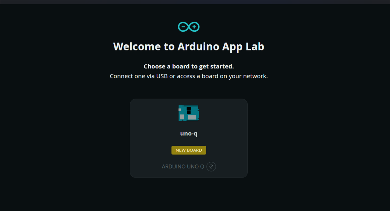
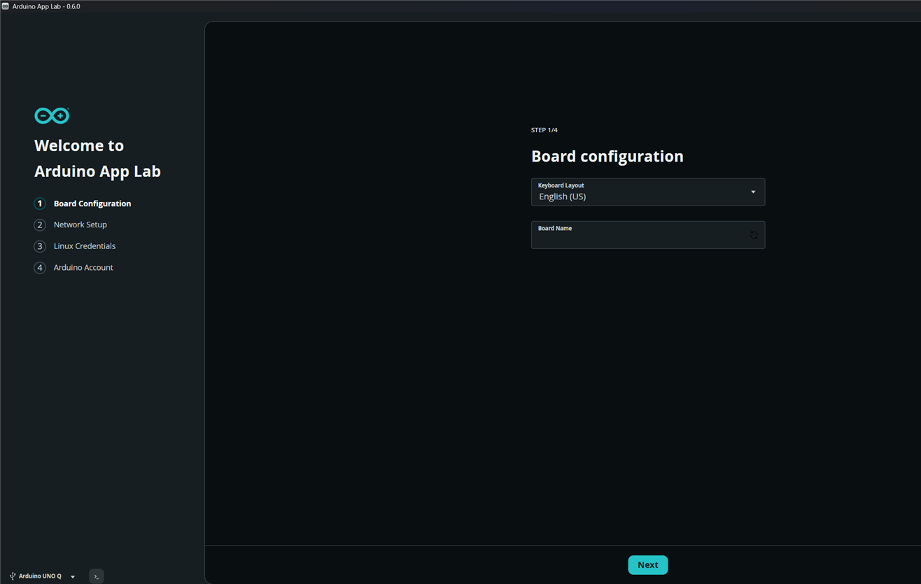
So, the Arduino UNO Q board is detected automatically. I clicked on the board name, and App Lab redirected me to the following configuration interface. I gave a name to the board (I tried a name with _ but failed) and clicked on the next button at the bottom.
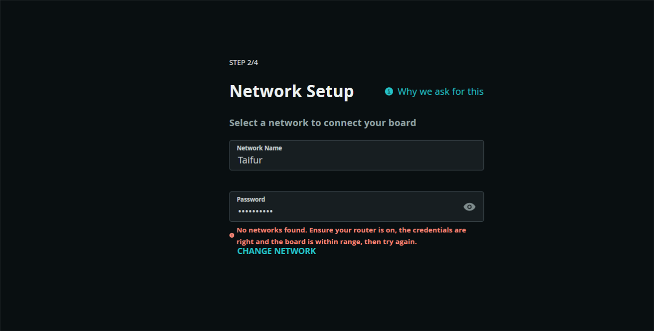
It guided me to the network setup window, but I was getting the following error message, though my WiFi password was correct. I tried multiple times and got the same message. So, I skipped the network setup option.
After setting the Linux password, App Lab started successfully with several examples.
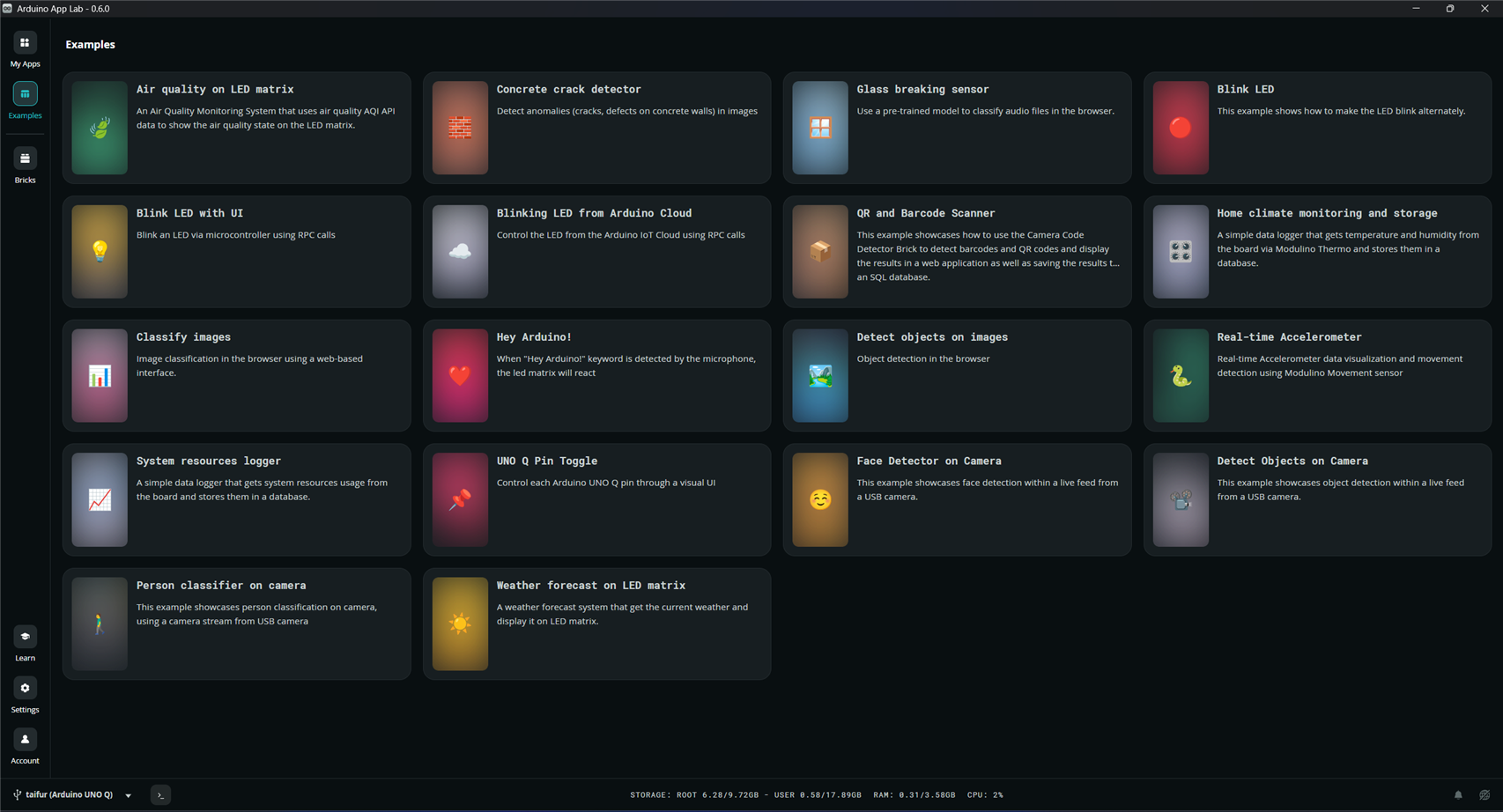
I opened the Blink LED example as my first experiment. After opening the Blink LED app, a notification appeared to update the App Lab. I updated the app, but then I noticed that App Lab was stuck on the board configuration page. I clicked the “Next” button, but nothing happened. I closed the app and ran it again, but I still faced the same problem. I also connected and disconnected the Arduino UNO Q board several times, but the issue remained unchanged. Finally, after restarting my PC, the problem was solved.
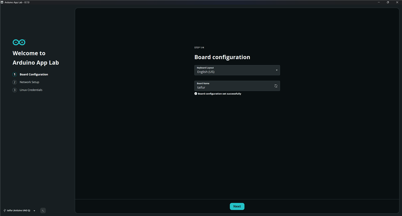
The updated App Lab ran with some new examples.
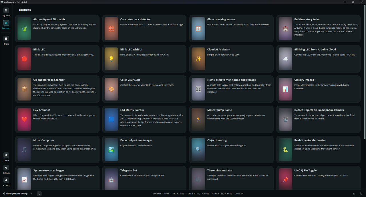
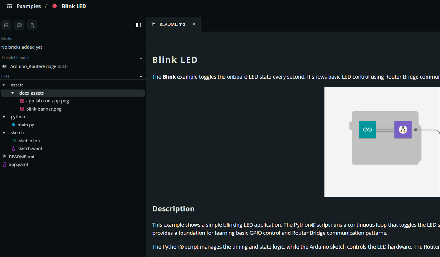
I opened the Blink LED example, read the README document, and realized that it is quite different from the traditional Blink LED examples used with other Arduino boards. In this example, both the MPU and MCU are involved in controlling the LED. The MPU, programmed in Python, calculates the timing interval, while the MCU, programmed using traditional Arduino programming (C++), actually turns the LED ON and OFF based on the timing information provided by the MPU. The Router Bridge enables communication between the MPU and MCU.
The following screenshot shows the structure of the Blink LED program.
After successfully testing the Blink LED program, I became curious to try a few more examples. However, I realized that most of the examples depend on external hardware such as a camera or microphone, and require the Arduino UNO Q to run either in network mode or single-board computer mode.
Before moving on to those examples, I decided to write and test a small program in host mode. For this experiment, I connected a 4-digit seven-segment display module to the Arduino UNO Q using male-to-female jumper wires. My goal is to create a digital clock where the time will be read by the MPU using Python, then transferred to the MCU through the Router Bridge, and finally displayed on the seven-segment module.
For my project, the following Python code is used. From the screenshot, it can be clearly seen that the current time is being displayed in the Python console. The hour and minute values are then combined into a single number and transmitted to the MCU through the Router Bridge.

The following Arduino code was used to receive the time value and display it to the seven-segment display.
#include "Arduino_RouterBridge.h"

// Pin definitions
int g = 2, f = 3, e = 4, d = 5, c = 6, b = 7, a = 8;
int d1 = 9, d2 = 10, d3 = 11, d4 = 12;

int time_value = 0;

// Segment patterns for digits 0-9
// Segments: a, b, c, d, e, f, g
const bool digits[10][7] = {
  {0,0,0,0,0,0,1}, // 0
  {1,0,0,1,1,1,1}, // 1
  {0,0,1,0,0,1,0}, // 2
  {0,0,0,0,1,1,0}, // 3
  {1,0,0,1,1,0,0}, // 4
  {0,1,0,0,1,0,0}, // 5
  {0,1,0,0,0,0,0}, // 6
  {0,0,0,1,1,1,1}, // 7
  {0,0,0,0,0,0,0}, // 8
  {0,0,0,0,1,0,0}  // 9
};

int segmentPins[7] = {a, b, c, d, e, f, g};
int digitPins[4]   = {d1, d2, d3, d4};


void setup() {

  int segPins[] = {a, b, c, d, e, f, g};
  for (int i = 0; i < 7; i++) pinMode(segPins[i], OUTPUT);

  int digitPins[] = {d1, d2, d3, d4};
  for (int i = 0; i < 4; i++) {
    pinMode(digitPins[i], OUTPUT);
    digitalWrite(digitPins[i], HIGH); // All digits OFF initially
  }

  Bridge.begin();
  Bridge.provide("time_set", time_set);

}

// Turn off all digit select pins (deactivate all digits)
void clearDigits() {
  digitalWrite(d1, HIGH);
  digitalWrite(d2, HIGH);
  digitalWrite(d3, HIGH);
  digitalWrite(d4, HIGH);
}

// Display a single-digit pattern on the segments
void showDigit(int num) {
  digitalWrite(a, digits[num][0]);
  digitalWrite(b, digits[num][1]);
  digitalWrite(c, digits[num][2]);
  digitalWrite(d, digits[num][3]);
  digitalWrite(e, digits[num][4]);
  digitalWrite(f, digits[num][5]);
  digitalWrite(g, digits[num][6]);
}

void displayNumber(int number) {
  if (number < 0)    number = 0;
  if (number > 9999) number = 9999;

  int thousands = number / 1000;
  int hundreds  = (number / 100) % 10;
  int tens      = (number / 10) % 10;
  int ones      = number % 10;

  int digitValues[4] = {thousands, hundreds, tens, ones};
  int digitPins[4]   = {d1, d2, d3, d4};

  for (int i = 0; i < 4; i++) {
    // Step 1: Turn OFF all digits first
    clearDigits();

    // Step 2: Blank all segments (HIGH = off for active-LOW segments)
    digitalWrite(a, HIGH);
    digitalWrite(b, HIGH);
    digitalWrite(c, HIGH);
    digitalWrite(d, HIGH);
    digitalWrite(e, HIGH);
    digitalWrite(f, HIGH);
    digitalWrite(g, HIGH);

    // Step 3: Small blanking pause so old segments fully turn off
    delayMicroseconds(50);

    // Step 4: Set correct segments for this digit
    showDigit(digitValues[i]);

    // Step 5: Activate this digit
    digitalWrite(digitPins[i], LOW);

    // Step 6: Hold for persistence of vision
    delayMicroseconds(2500);
  }
}


void loop() {
   displayNumber(time_value);
}

void time_set(float time) {
    // LOW state means LED is ON
   time_value = time;
}
The following image shows the hardware setup and the result.

So, I successfully modified an example program to build my own project without any difficulties. This is the end of the experiment, where my Arduino UNO Q was connected via a USB-C cable and serving in host mode. In the next stage of my experiment, I am going to connect my board in network mode.
I connected the USB-C Hub to the Arduino board and powered the hub externally. The Arduino started successfully in single-board computer mode and became discoverable from the Arduino App Lab.
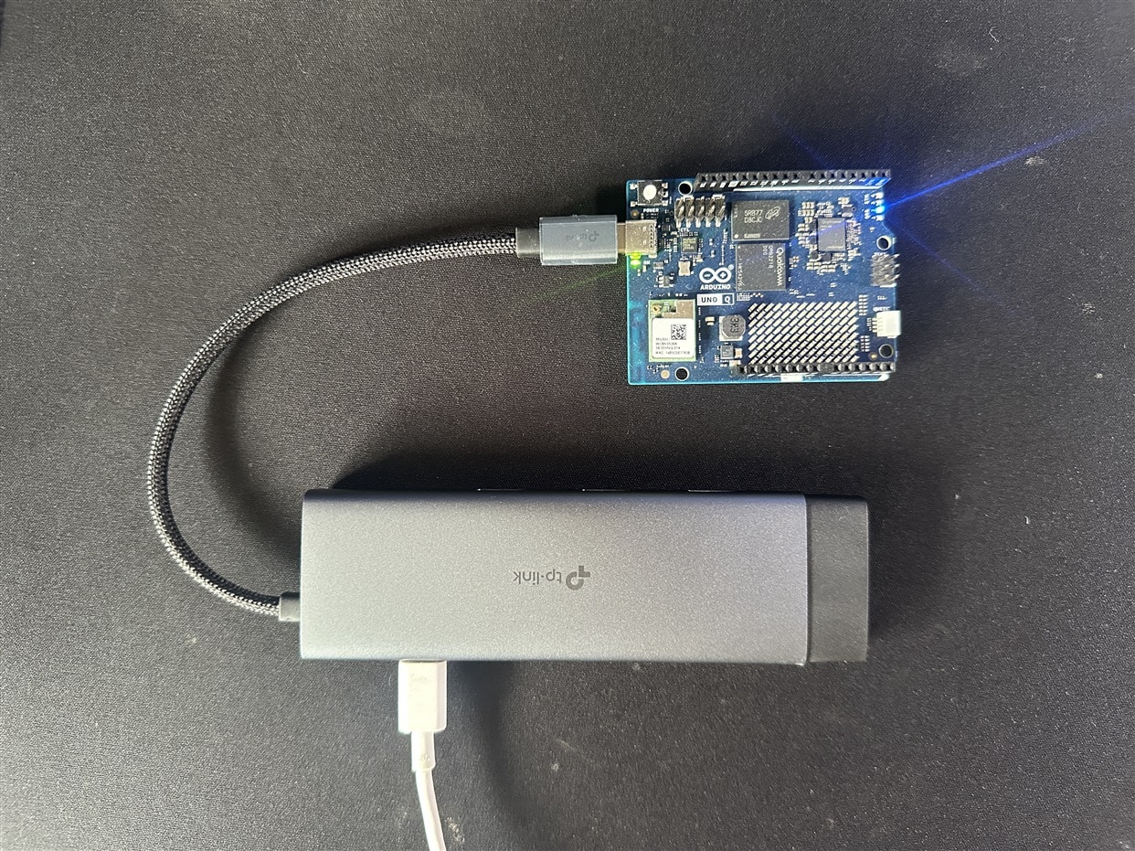
I then opened the Blink LED with UI example and ran the application. The browser window opened automatically, and the application worked as expected. The documentation provided with the app was also very clear and easy to understand.

In this stage, I was curious to check whether SSH was working or not. So, I opened PuTTY and entered the IP address of the Arduino UNO Q. The board responded immediately, confirming that the SSH connection was working properly.
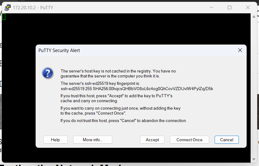
After accepting, I entered the name and password for the board and got the following response.
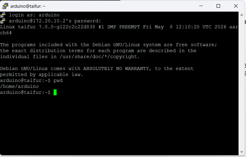
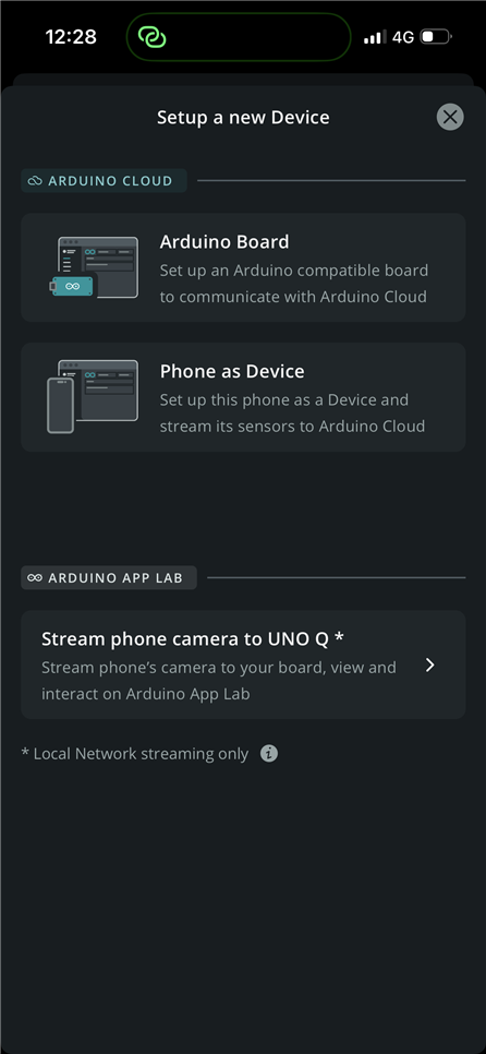
In the next step, I tried to run an object detection application on the Arduino UNO Q. Normally, object detection requires a USB camera connected directly to the board. However, I found an example application called “Detect Object on Smartphone Camera.” Before connecting an external camera to the Arduino UNO Q, I was interested in testing object detection using my smartphone camera with the board. I carefully read the documentation to understand how the application works. After that, I downloaded the Arduino IoT Cloud Remote app and logged into it successfully.
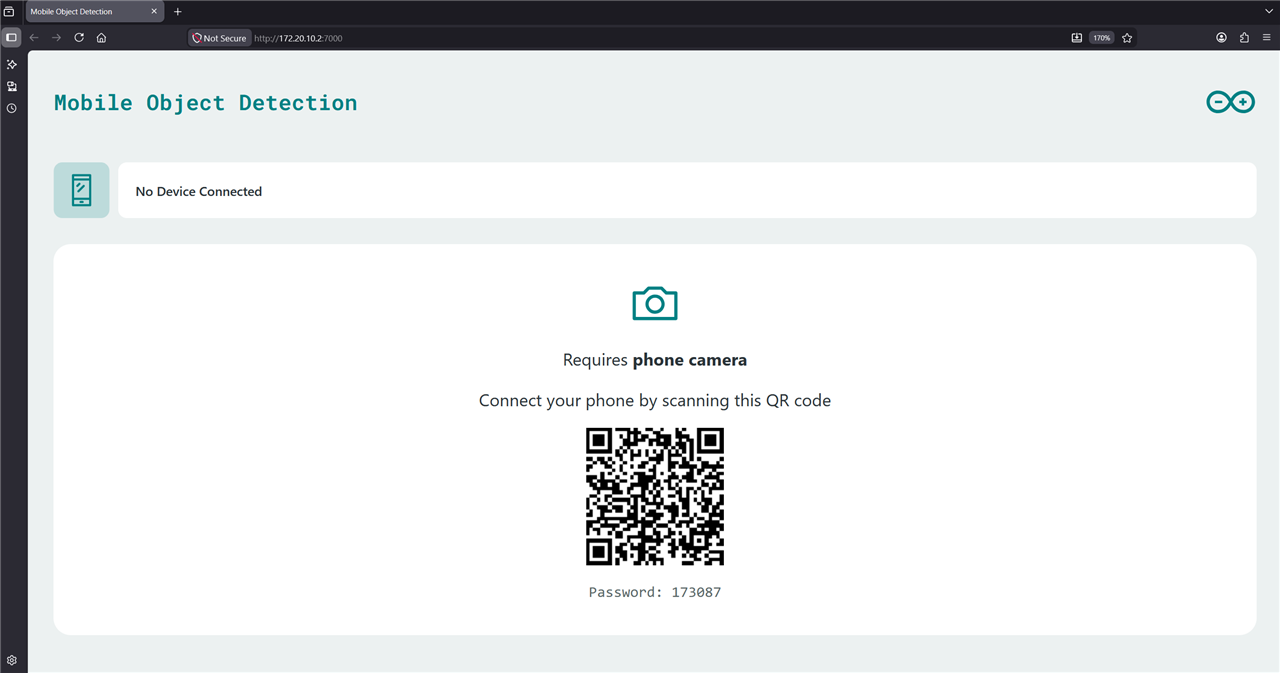
From the App Lab, I clicked on the Run button. It took a few minutes to download and extract the required model and supporting files before deploying the application to the board. After the setup was completed, the following browser window opened automatically, displaying a QR code to connect the smartphone camera.
Now it was time to connect the smartphone camera. To do that, I selected the “Stream Phone Camera to UNO Q” option from the smartphone app. During this step, I encountered an interesting issue.
Initially, I was unable to connect the Arduino UNO Q board to my router’s Wi-Fi network, possibly because my Wi-Fi SSID contained an “&” character. To work around the problem, I enabled the hotspot on my iPhone and connected both my PC and the Arduino board to the hotspot network. However, when I tried to connect the smartphone camera to the UNO Q, the app displayed a message indicating that the phone itself also needed to be connected to the same Wi-Fi network.
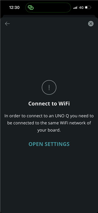
It was a strange issue at first, but logically understandable. The phone was using mobile data while simultaneously acting as a Wi-Fi hotspot. To resolve the connection problem, I renamed my Wi-Fi SSID by removing the “&” character, and after that, the connection worked successfully.
The Arduino UNO Q then became discoverable from my phone. I connected the board to the mobile app using the password displayed in the browser window, and the detection result appeared instantly in the browser.
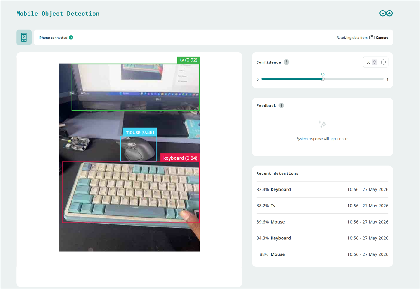
It successfully detected my keyboard, mouse, and monitor with a high level of confidence. I was very impressed with the response time of the system. It also demonstrated excellent performance in detecting multiple objects within a single frame, as shown in the following screenshot.
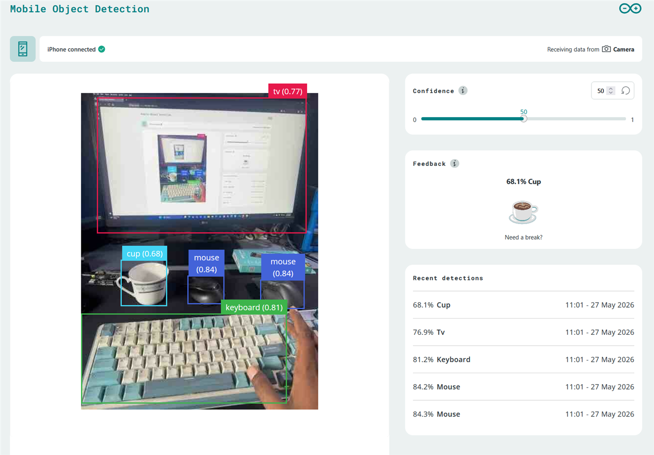
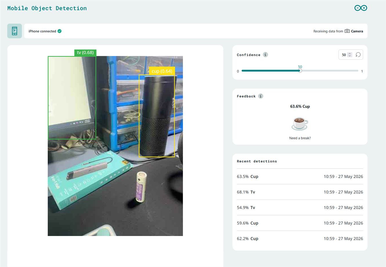
It detected my Amazon Echo device as a cup. I also tried detecting my headphones, a Li-ion battery, and my 3D printer, but the model was unable to recognize them successfully.
In the next phase, I am going to connect my web camera to the Arduino UNO Q.
The next day...............
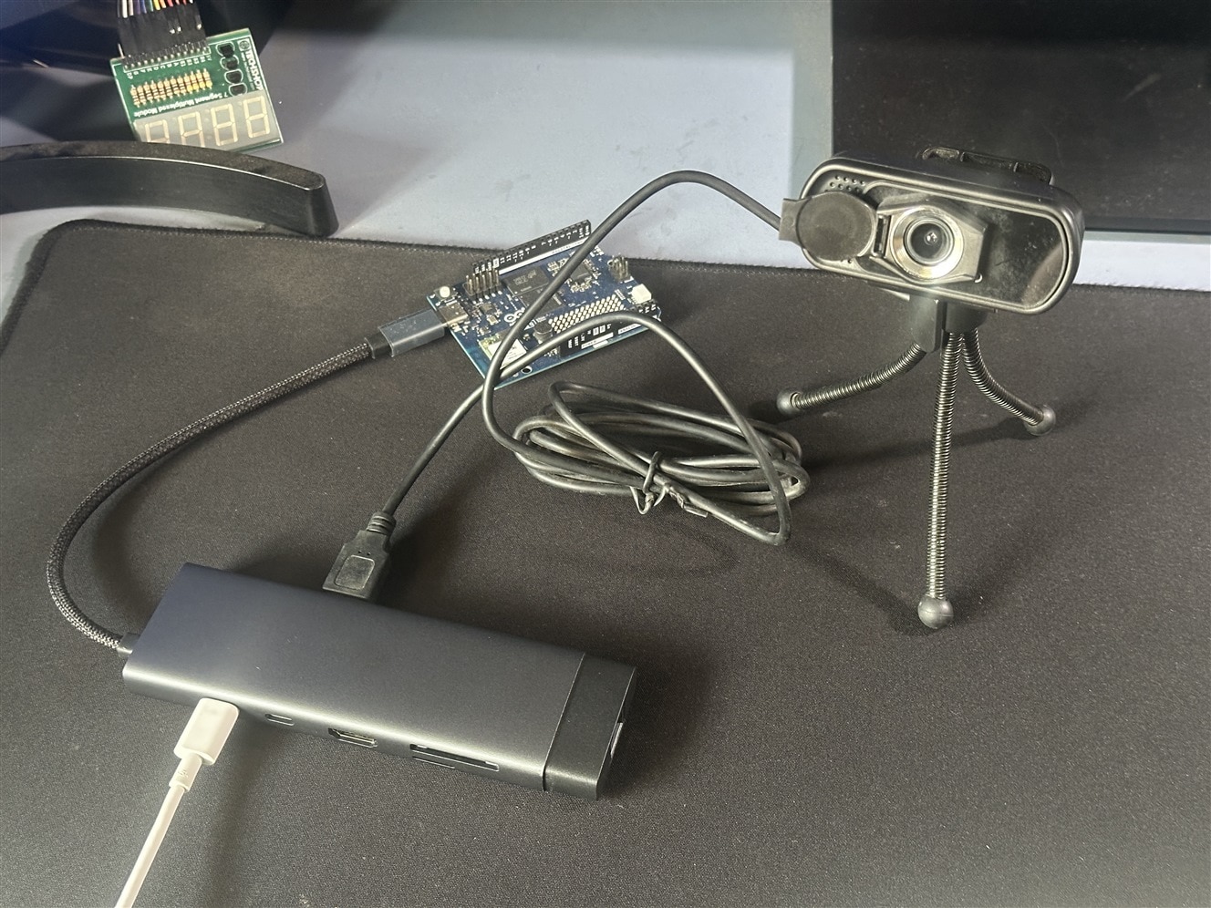
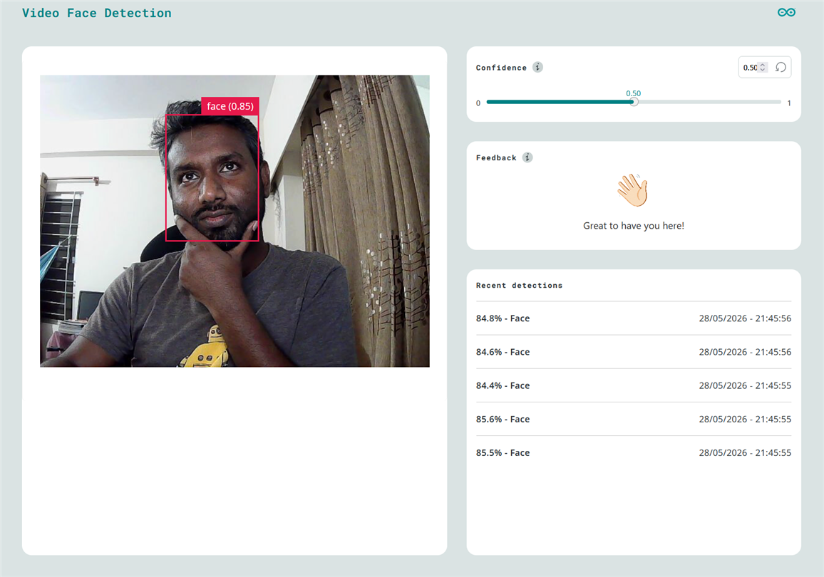
I connected my USB webcam through the USB-C hub and then opened the Arduino App Lab. After launching the “Face Detection on Camera” example application, a browser window opened automatically, and the camera successfully detected me without any driver-related issues. The application detected my face with around 85% confidence. Initially, the response was almost real-time, but after a short while, I noticed nearly a 10-second delay in the camera streaming. This could possibly be caused by my slow network connection, although I am not completely sure.
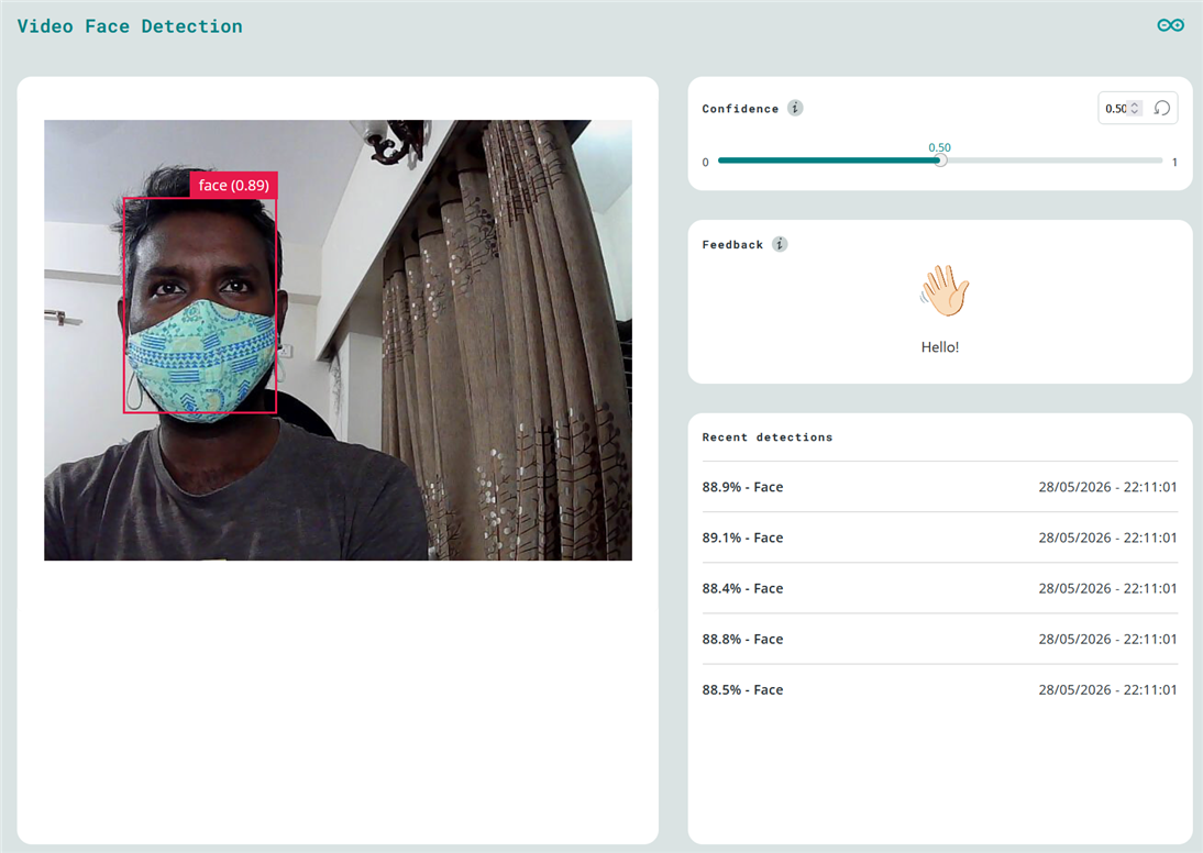
Even with a musk, the accuracy was quite good.
After completing the face detection experiment, I opened the “Detect Object on Camera” application. The app ran perfectly and successfully detected me as a person. However, after a short time, I noticed some distortion and visual artifacts in the camera image, as shown in the screenshot below.
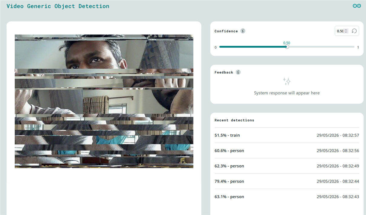
I disconnected and reconnected the board’s power, then relaunched the App Lab and ran the example application again. This time, I tried detecting my phone, but after a short while, I encountered the same issue again.
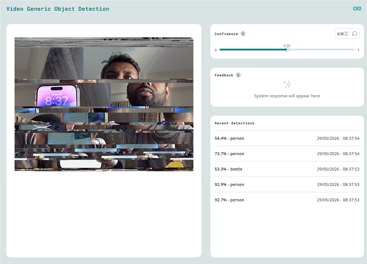
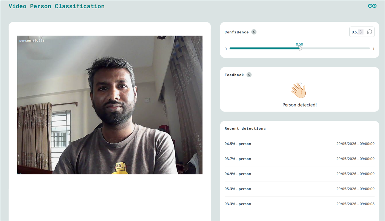
I was curious to understand why this was happening. Suddenly, one thing came to mind: I had been using a 2A smartphone power adapter to power the board through the external USB hub. I decided to try the power adapter that came with the Roadtest kit instead. After connecting the Multicomp Pro MP009260 30W power supply, the problem was solved. I successfully tried the Person Classifier on Camera.
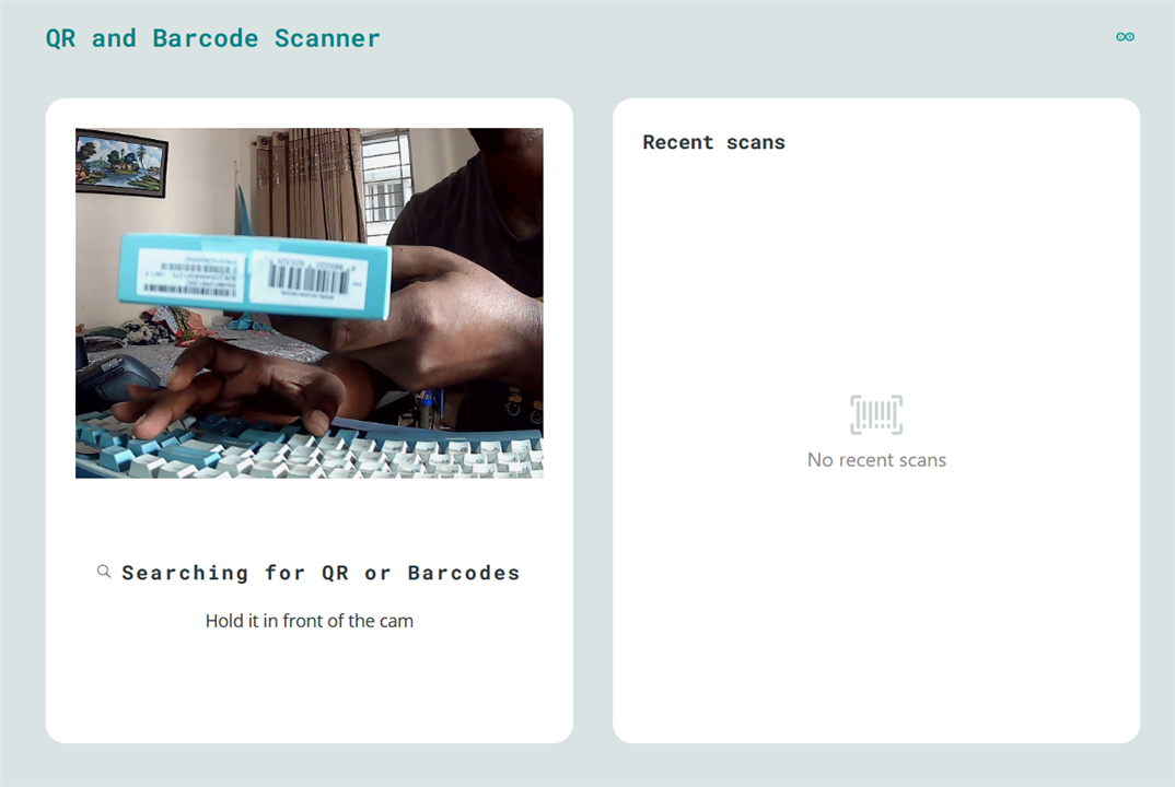
I tried to read Barcode and QR code using the QR and Barcode Scanner example app, but I failed to read either. I tried from a different distance and angle, but I was out of luck.
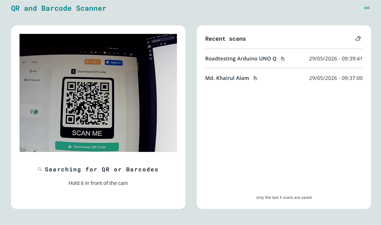
I suspected the codes I had tested were too small, so I generated a few QR codes and barcodes on my computer and tried again. This time, the app successfully read them.
In this stage, I connected and tested the SparkFun QWIIC Environmental Combo Sensor with the Arduino UNO Q. The connection process was straightforward, thanks to the QWIIC ecosystem's plug-and-play design. I simply connected the QWIIC Environmental Combo Sensor to the Arduino UNO Q's QWIIC connector using a short QWIIC cable, no soldering or complex wiring required.

After connecting the QWIIC sensor, the next step is to write the code. I created a new App in App Lab named "Environmental Monitoring." I downloaded two libraries (SparkFun BME280 & SparkFun CCS811) for the sensor.
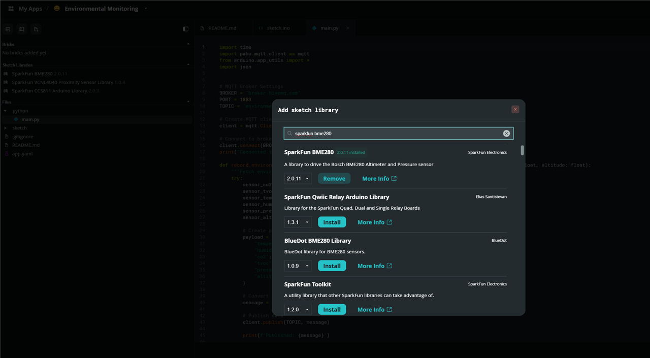
Then, with the help of the example programs, I wrote the code for reading the sensor data. I was facing problem interfacing the sensor using I2C, and suddenly I realized that the QWIIC port is connected to Wire1 instead of Wire. So, I modified the code and successfully got the sensor data as shown in the screenshot.

The following is the full sketch for the MCU side.
#include <Wire.h>
#include <Arduino_RouterBridge.h>

#include "SparkFunCCS811.h"
#include "SparkFunBME280.h"

#define CCS811_ADDR 0x5B

CCS811 ccs881Sensor(CCS811_ADDR);
BME280 bme280Sensor;

float co2, tvoc, temperature, humidity, pressure, altitude;

void setup()
{
  Monitor.begin();
  Wire1.begin(); //Inialize I2C Hardware
  Bridge.begin();

  if (ccs881Sensor.begin(Wire1) == false)
  {
    Monitor.print("CCS811 error. Please check wiring. Freezing...");
    while (1);
  }

  if (bme280Sensor.beginI2C(Wire1) == false)
  {
    Monitor.println("The bme280 sensor did not respond. Please check wiring.");
    while(1);
  }

}

void loop()
{
  //Check to see if data is ready with .dataAvailable()
  if (ccs881Sensor.dataAvailable())
  {
    //If so, have the sensor read and calculate the results.
    //Get them later
    ccs881Sensor.readAlgorithmResults();

    Monitor.print("CO2: ");
    //Returns calculated CO2 reading
    co2 = ccs881Sensor.getCO2();
    Monitor.print(co2);
    Monitor.print(" tVOC: ");
    //Returns calculated TVOC reading
    tvoc = ccs881Sensor.getTVOC();
    Monitor.print(tvoc);

    Monitor.print(" Humidity: ");
    humidity = bme280Sensor.readFloatHumidity();
    Monitor.print(humidity, 0);

    Monitor.print(" Pressure: ");
    pressure = bme280Sensor.readFloatPressure();
    Monitor.print(pressure, 0);

    Monitor.print(" Alt: ");
    //Serial.print(mySensor.readFloatAltitudeMeters(), 1);
    altitude = bme280Sensor.readFloatAltitudeFeet();
    Monitor.print(altitude, 1);

    Monitor.print(" Temp: ");
    //Serial.print(mySensor.readTempC(), 2);
    temperature = bme280Sensor.readTempF();
    Monitor.print(temperature, 2);

    Monitor.println();
    Monitor.println(".......................................................................................");

    Bridge.notify("record_environmental_sensor", co2, tvoc, temperature, humidity, pressure, altitude);

  }

  delay(1000); //Don't spam the I2C bus
}
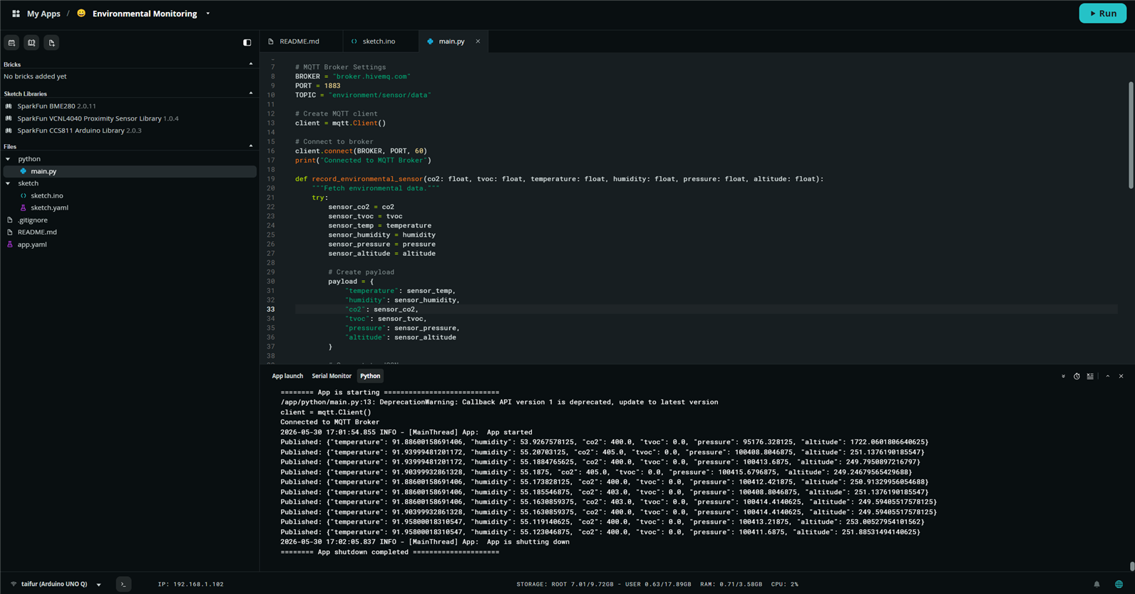
I used the bridge library to send the sensor data to the MPU. On the MPU side, I used a Python script to process the sensor data and send it to an MQTT broker. I looked for the MQTT Brick but did not find any Brick for MQTT, so I decided to use the paho-mqtt package for writing the Python code and sending the data over MQTT. The paho-mqtt client is not preinstalled in Arduino UNO Q. So, connected the UNO Q in network mode, open SSH, and use the following command to install the client:
sudo apt install python3-paho-mqtt
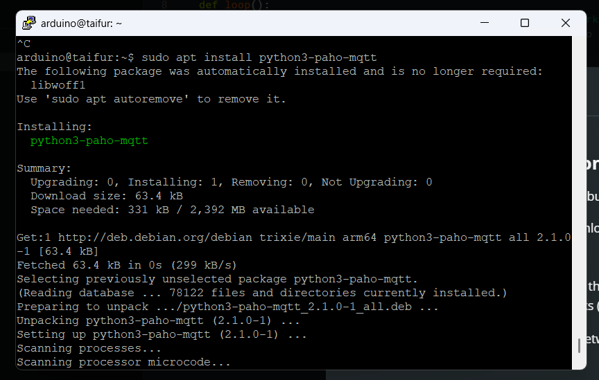
The paho-mqtt client was successfully installed without any issues. Then I wrote the following Python script to receive data from the MCU and send it to an MQTT Broker.
import time
import paho.mqtt.client as mqtt
from arduino.app_utils import *
import json


# MQTT Broker Settings
BROKER = "broker.hivemq.com"
PORT = 1883
TOPIC = "environment/sensor/data"

# Create MQTT client
client = mqtt.Client()

# Connect to broker
client.connect(BROKER, PORT, 60)
print("Connected to MQTT Broker")

def record_environmental_sensor(co2: float, tvoc: float, temperature: float, humidity: float, pressure: float, altitude: float):
    """Fetch environmental data."""
    try:
        sensor_co2 = co2
        sensor_tvoc = tvoc
        sensor_temp = temperature
        sensor_humidity = humidity
        sensor_pressure = pressure
        sensor_altitude = altitude

        # Create payload
        payload = {
            "temperature": sensor_temp,
            "humidity": sensor_humidity,
            "co2": sensor_co2,
            "tvoc": sensor_tvoc,
            "pressure": sensor_pressure,
            "altitude": sensor_altitude
        }

        # Convert to JSON
        message = json.dumps(payload)

        # Publish data
        client.publish(TOPIC, message)

        print(f"Published: {message}")

    except Exception as e:
        #logger.exception(f"sensor data receive: Error: {e}")
        print(f"sensor data receive: Error: {e}")

# Allow the microcontroller to call the "get_air_quality" function
Bridge.provide("record_environmental_sensor", record_environmental_sensor)

#logger.info("Starting App...")

# See: https://docs.arduino.cc/software/app-lab/tutorials/getting-started/#app-run
App.run()
The MQTT client was successfully connected and was publishing data to the MQTT broker on a specific topic for every sensor data received from the MCU.
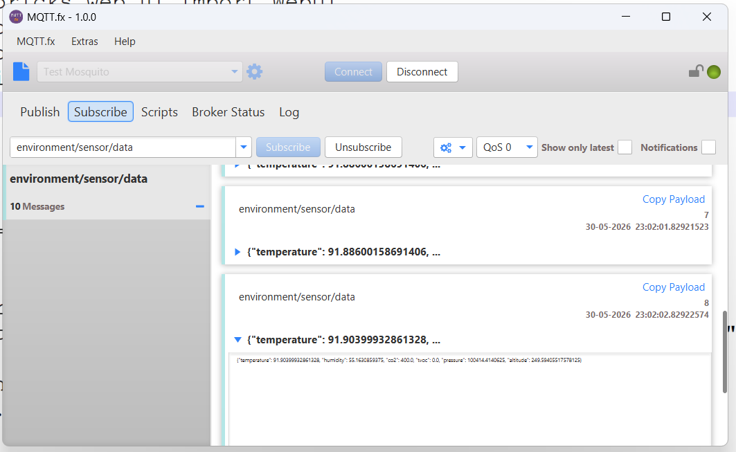
I used MQTT.fx to check whether the data has reached to the broker or not. I subscribed to that specific topic and successfully received the data.
For installing Node-RED, I installed Node.js successfully on the Arduino UNO Q board using the command:
sudo apt-get install -y nodejs. Node.js v20 was installed automatically.
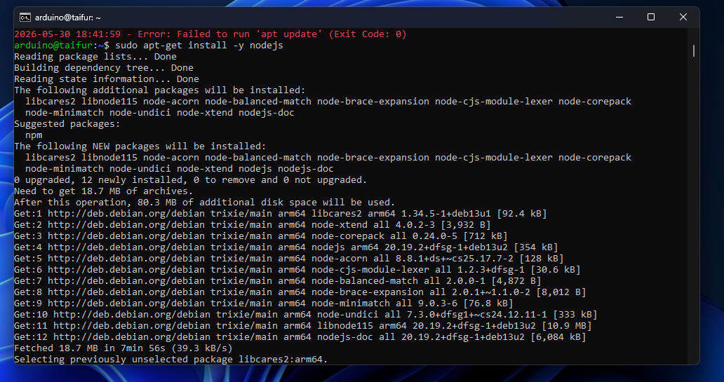
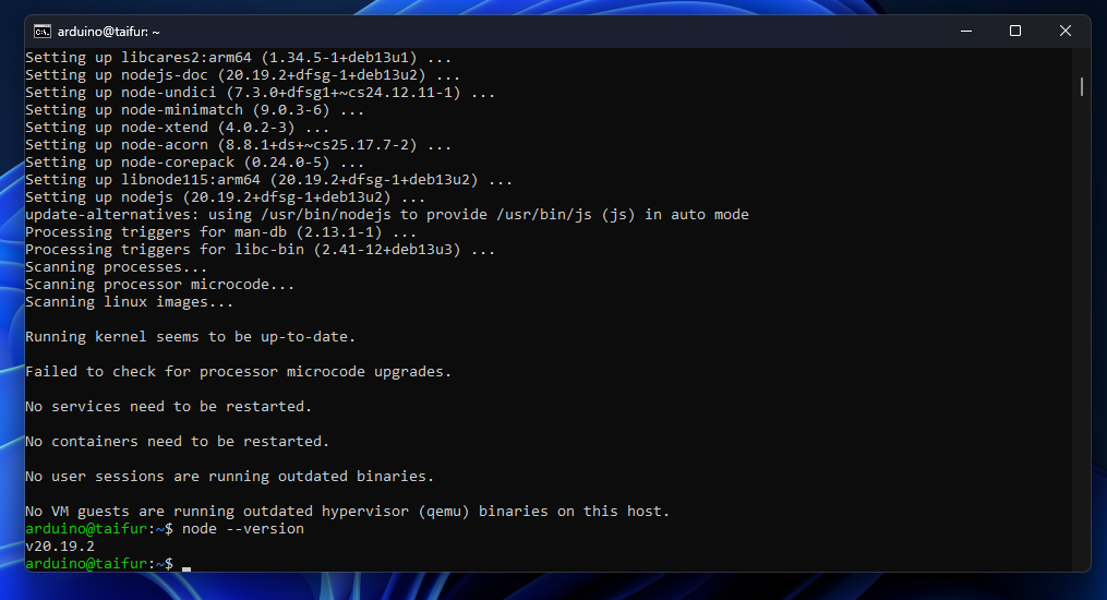
For installing any node package, I need npm. So, I installed npm as it is not already installed.
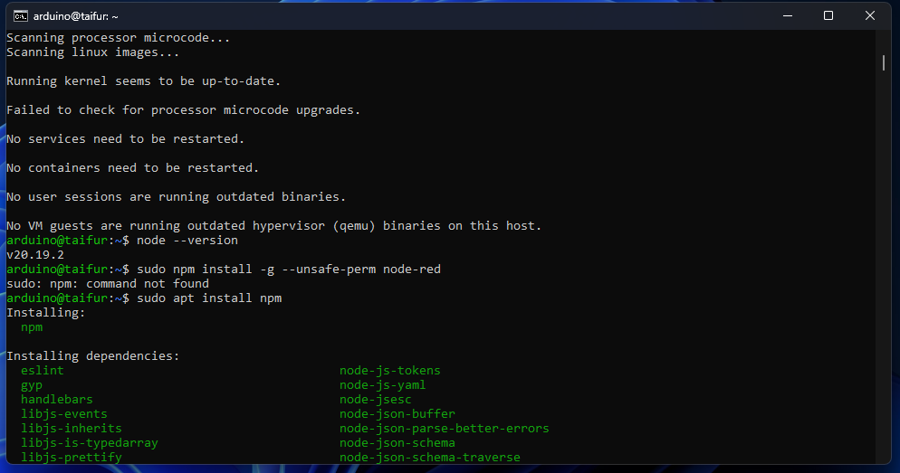
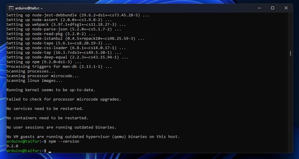
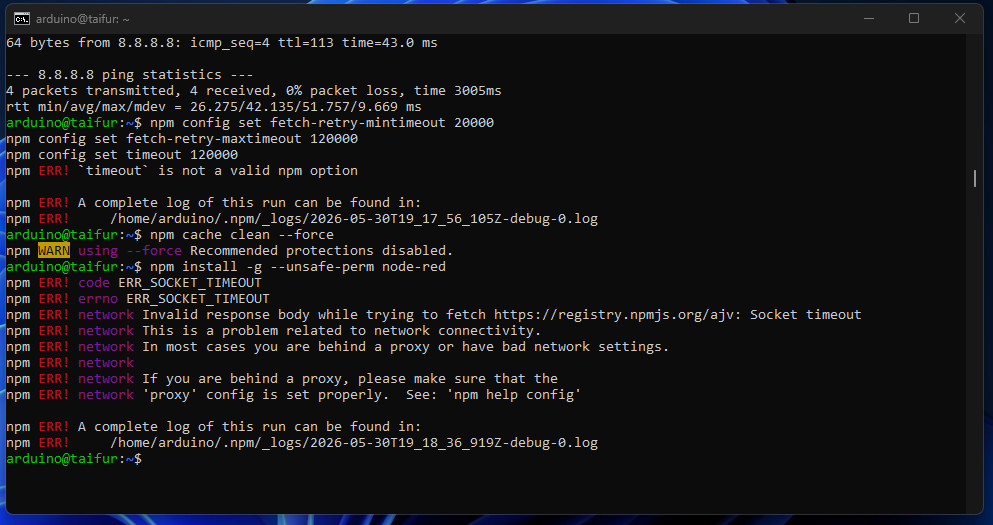
Then I tried to install Node-RED using the npm command, and I got the following error messages. I tried multiple times but got the same result. I tried to find a tutorial on installing Node-RED on an Arduino Uno Q, but did not find one. I tried to solve the issues in different ways I found on the internet, but the problem has not been solved yet.
Next day..............
I did some research on the internet, and I started to install Node-RED again with a fresh mind on my Arduino UNO Q board. I browsed the official Node-RED page and accessed the option to install Node-RED on Debian-based OS like Raspberry Pi. I entered the following command on the board shell:
bash <(curl -sL https://github.com/node-red/linux-installers/releases/latest/download/update-nodejs-and-nodered-deb)
Everything went fine without installing the Node-Red core:
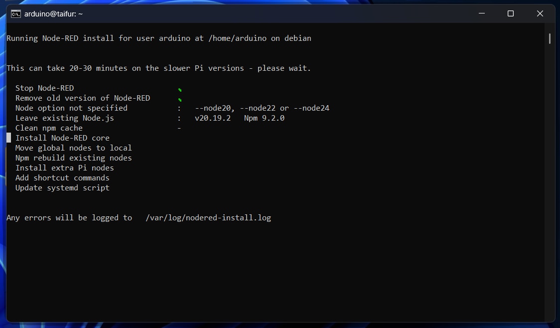
I entered the following command and tried again:
sudo apt install build-essential git curl
Still got the same result. Then I tried to install it with a specific version of Node with the following command:
bash <(curl -sL https://raw.githubusercontent.com/node-red/linux-installers/master/deb/update-nodejs-and-nodered) --node16
I was fortunate, and this time everything was installed successfully.
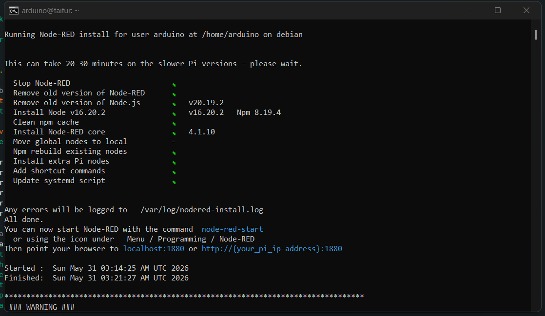
I started Node-RED using the following command:
node-red-start
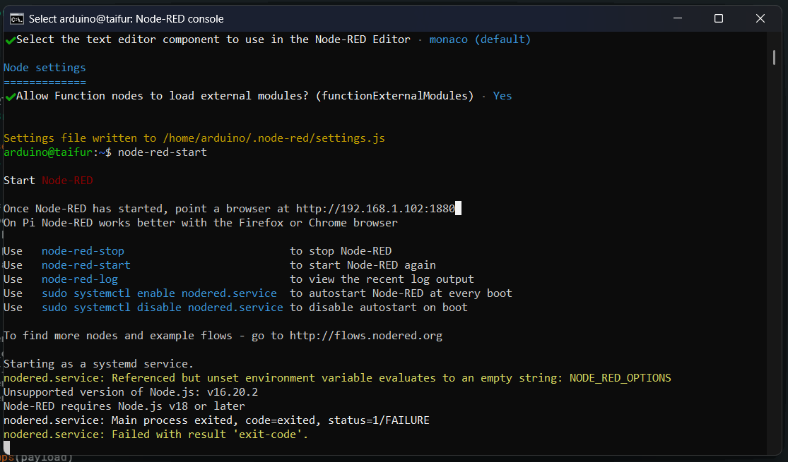
I got the error message that to run Node-RED, I need to update Node.js version 18 or later, but I have v16. No, it is time to update the Node.js version again. To install Node.js version 18, I entered the following command in the shell:
curl -fsSL https://deb.nodesource.com/setup_18.x | sudo -E bash -
Then I enter the command:
sudo apt install -y nodejs
Node version 18 was installed successfully.
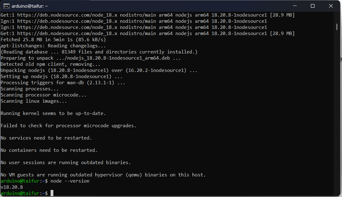
After updating Node.js, I tried to run Node-RED again, and this time it ran successfully.
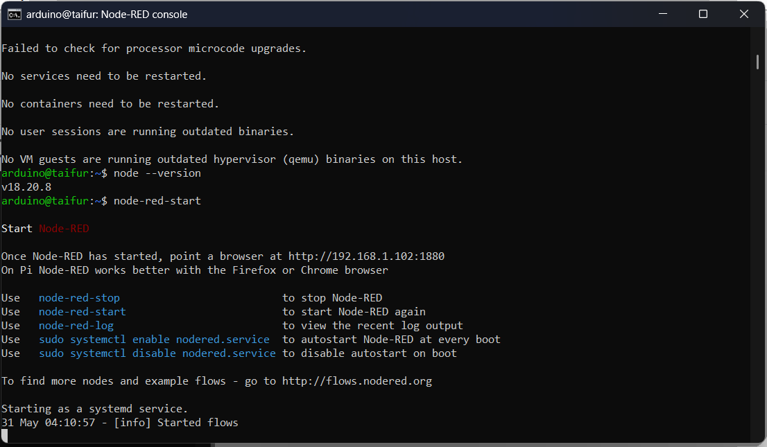
And Node-RED was loaded successfully.
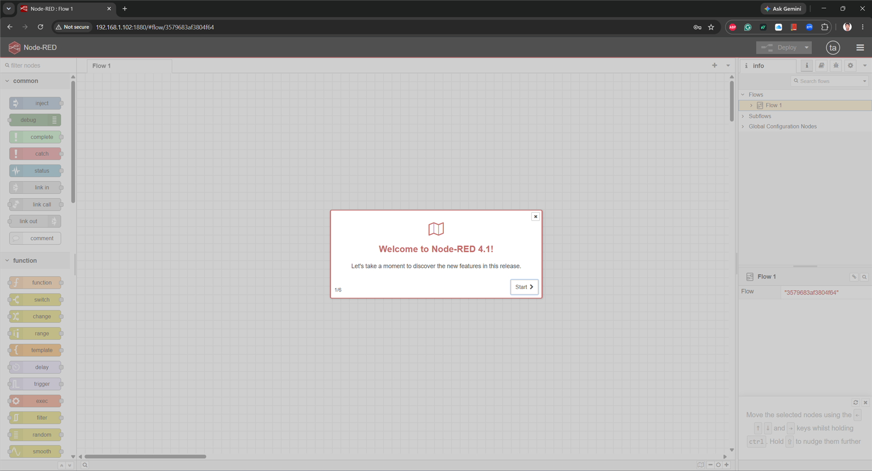
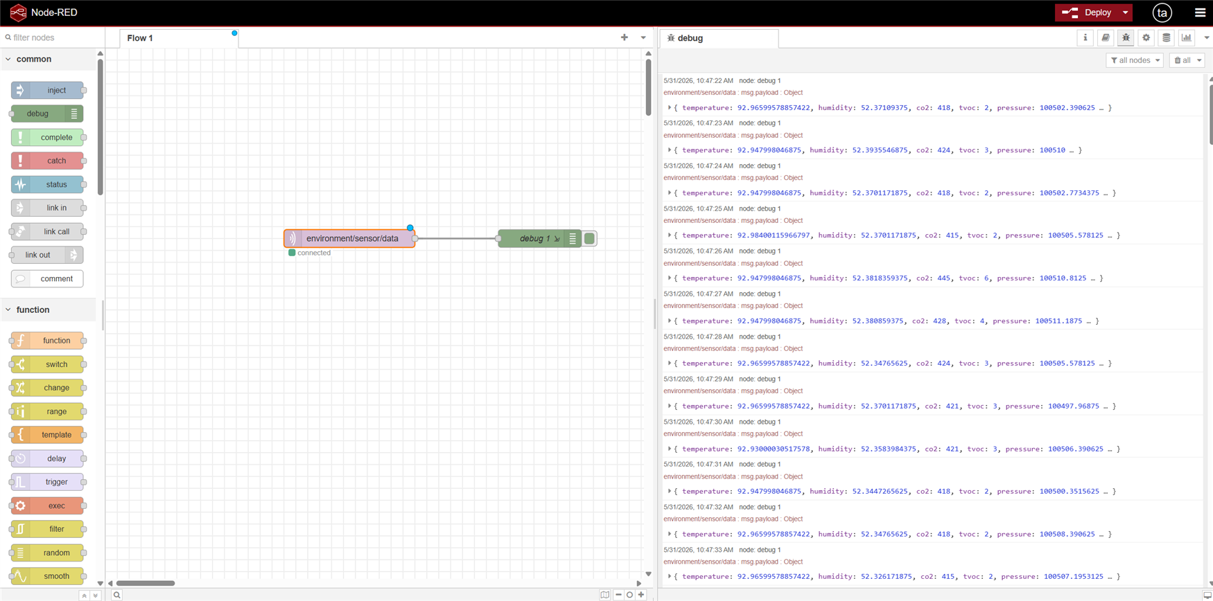
After installing Node-RED successfully, I want to make a simple flow to receive the MQTT message from the Arduino UNO Q and print the message in the debug console. The message was received and displayed successfully, as shown in the screenshot below.
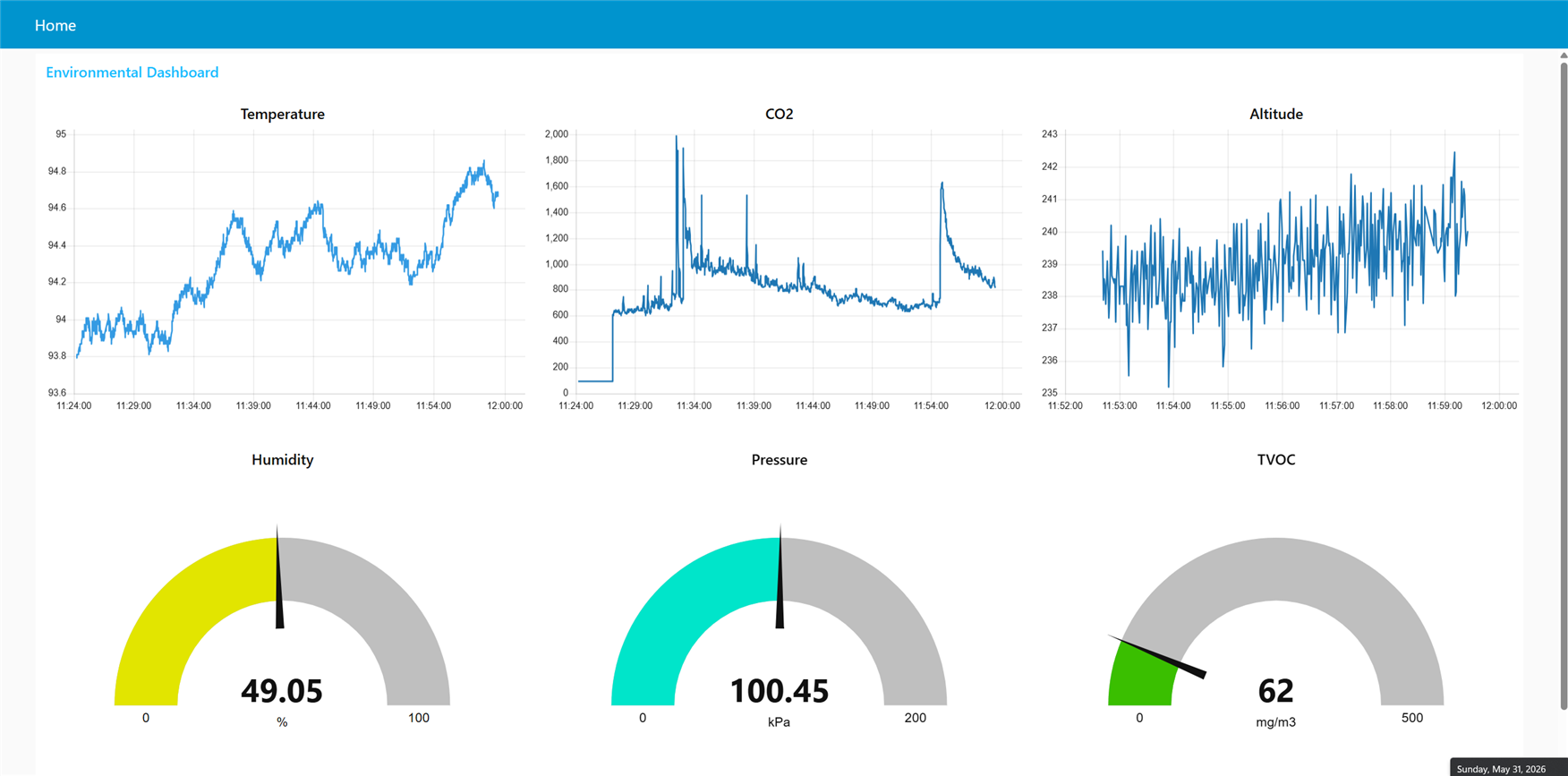
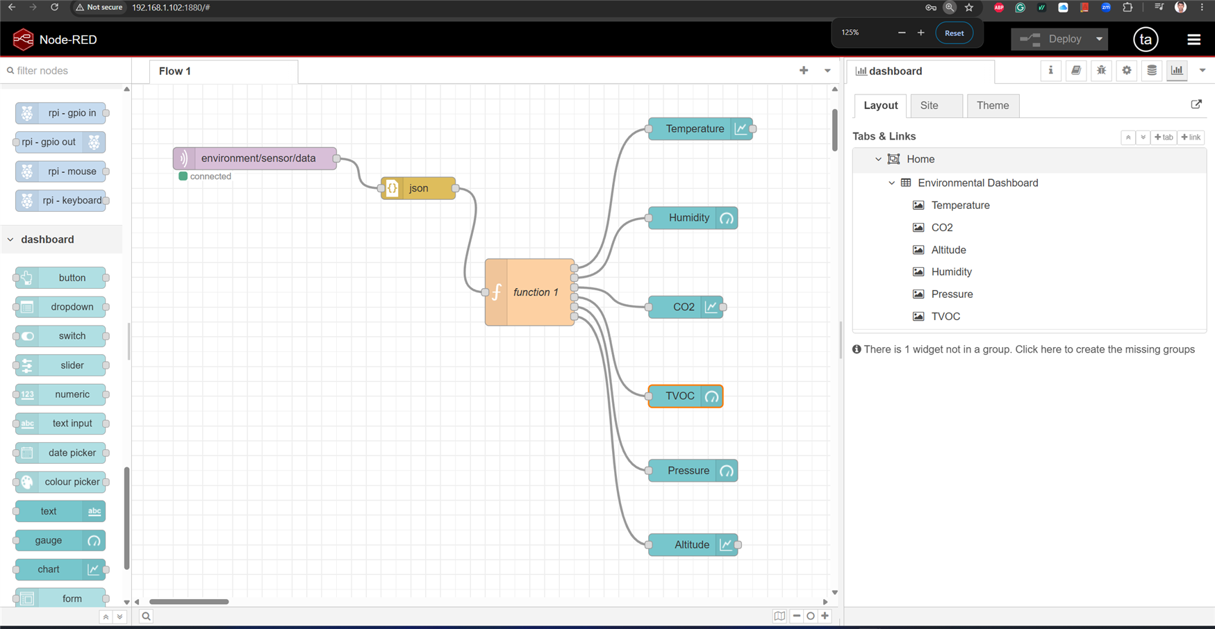
Then I made a dashboard to show all the environmental data received from the Arduino UNO Q to the MQTT Broker. Following is the node flow design for my dashboard project. The MQTT message contains JSON data, and the JSON string was separated using a simple function node. The function node contains the following code:
return [
    { payload: Number(msg.payload.temperature.toFixed(2)) },
    { payload: Number(msg.payload.humidity.toFixed(2)) },
    { payload: Number(msg.payload.co2.toFixed(2)) },
    { payload: Number(msg.payload.tvoc.toFixed(2)) },
    { payload: Number((msg.payload.pressure / 1000).toFixed(2)) },
    { payload: Number(msg.payload.altitude.toFixed(2)) }
];
And my dashboard looks like this with all the data visualization: