RoadTest: Apply to Test the Infineon PSOC™ Edge E84 AI Evaluation Kit
Author: giemme2009
Creation date:
Evaluation Type: Development Boards & Tools
Did you receive all parts the manufacturer stated would be included in the package?: True
What other parts do you consider comparable to this product?: Rugged Raspberry Pi cyberdecks, custom STM32N6 + external NPU boards, or Meshtastic + sensor nodes. This kit stands out for tight integration of 60 GHz radar + dual PDM mics + environmental sensors + dual NPU (Ethos-U55 + NNLite) on one low-power MCU with native DSI and rich expansion. Fewer failure points than multi-board stacks.
What were the biggest problems encountered?: Setup was exceptionally smooth. Board recognised immediately as KitProg3 USB-UART on Windows 11. Only prerequisite was a free myInfineon account. First build/flash of Hello World worked end-to-end. The unpopulated J3 power header is noted as a feature for deliberate, field-repairable power architecture.
Detailed Review:
 Edge E84 AI Kit — RoadTest Edge E84 AI Kit RoadTest — Part 1
Status of this part. The hands-on work is done from my own bench: unboxing, first power-up, PC recognition, the documentation path, a microscope teardown (every part cross-checked against Infineon's kit docs), both factory demos, installing the Edge AI toolchain, and building, flashing, and running my own first project.
This first part evaluates the kit as it ships: unboxing and bring-up, a microscope teardown of the board, the two pre-loaded factory demos, installing the Edge AI development tools, and building and running a first project. Part 2 then takes the same board off the bench entirely, turning it into the Doomsday Cyberdeck — a self-contained, solar-powered, air-gapped Edge AI node.
The kit arrives in a compact, high-quality retail box — Infineon's "How will you bring AI to life?" packaging, small enough to sit in your palm. Inside, the board and the camera module are each held in cut black foam, together inside an antistatic bag — well protected for shipping.
The two items in the box match the quick-start guide's contents list: the PSOC Edge E84 AI board and a 0.3 MP camera module.
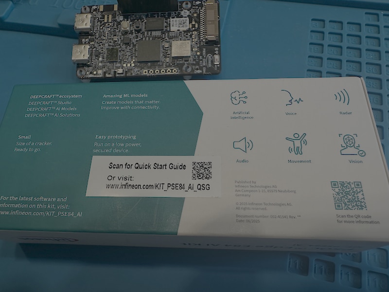
The box itself doubles as an orientation to the platform. Its back panel lays out the DEEPCRAFT ecosystem and the kit's six target use cases — artificial intelligence, voice, radar, audio, movement, and vision — and carries a QR code straight to the quick-start guide.
Figure 1— Kit contents
The board and the OV7675 camera module in the foam tray.
Figure — Box panel
The capability icons and QSG QR code on the box.
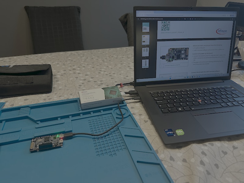
Following the quick-start guide, I connected the board to the PC with the USB-C cable at connector J1. The amber power LED (LED5) came on, and the green LED (LED1) began blinking — the sign that the pre-loaded out-of-box demo is running. The board was live within seconds of plugging in.
Figure — Powered board
The board powered over USB-C with its LEDs lit.
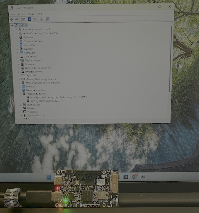
On my Windows 11 laptop the board was recognised immediately — no driver hunting. It enumerated as KitProg3 USB-UART (COM5) under Ports (COM & LPT) in Device Manager.
I then opened Tera Term on COM5 (the KitProg3 USB-UART bridge), and after reset the board presented the OOB demo menu:
*************** PSOC Edge E84 AI Kit OOB demo ***************
1. Voice Assistant
2. Gesture Detection
Enter your choice:
Selecting an option launches the matching demo.
Figure — Device Manager
The board shown as KitProg3 USB-UART (COM5)
Figure — Boot menu
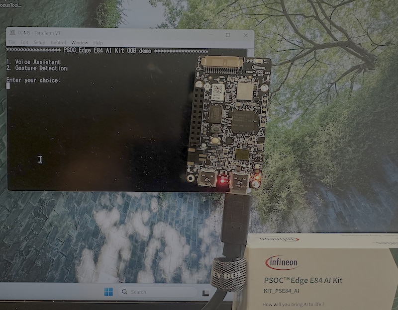
The OOB demo menu in Tera Term.
Getting started was guided by the Quick Start Guide, reachable directly from the QR code on the box (or at infineon.com). It's a short, four-page document that walks through the kit contents, connecting and powering the board, and bringing up the UART terminal — enough to reach the demos quickly. Each code example also ships with its own README and a design/implementation document inside the project
I went over the board under a USB microscope, read the markings off the major chips, and cross-checked each against Infineon's published kit documentation. Every part below is confirmed two ways: I could read it on the silicon, and it matches the kit's official feature list (and the BSP description in the tooling).
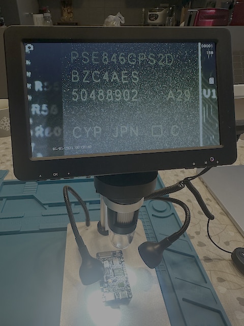
Edge E84 itselfThe headline part, in the centre of the board, is marked PSE846GPS2DBZC4A — the PSOC Edge E84 MCU. It pairs an Arm Cortex-M55 (with Helium DSP) and an Ethos-U55 NPU in a high-performance domain with a low-power Cortex-M33 (with Infineon's NNLite accelerator) for always-on work, plus a 2.5D GPU for the display path. Everything else on the board exists to feed this chip.
Figure — PSOC Edge E84 main MCU
PSE846GPS2DBZC4Ain the centre of the board.
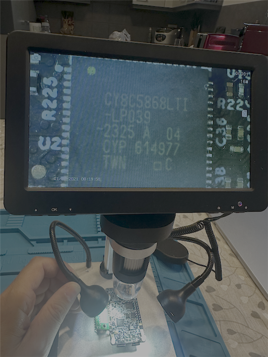
Under a small QR/serial label sat CY8C5868LTI-LP039, a Cypress/Infineon PSoC 5LP. On this board it's the KitProg3 — the onboard programmer/debugger and USB-UART (and USB-I2C) bridge: the chip behind the "one USB-C cable does everything" experience, and the same KitProg3 that showed up on COM5 in Section 4. Date code 2325 (week 23, 2025), Taiwan.
Figure — PSoC 5LP under the label
CY8C5868LTI-LP039, found beneath a QR label.
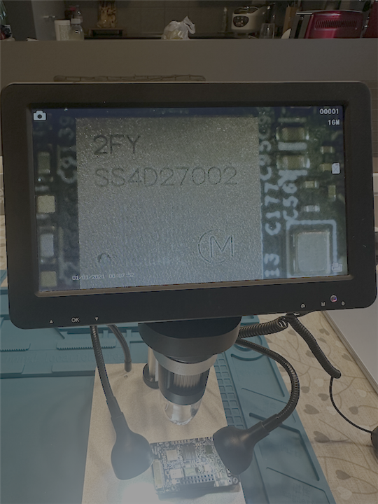
CYW55513)The module by the antenna carries the Murata logo and a 2FY mark (internal marking SS4D27002). That 2FY identifies it as the Murata Type 2FY (LBEE5HY2FY) module, which carries Infineon's AIROC CYW55513 Wi-Fi + Bluetooth (BLE 5.4) combo. Both radios come from this one module at the board edge, fed by the printed antenna.
Figure — Wireless module
Murata Type 2FY, next to the PCB antenna.
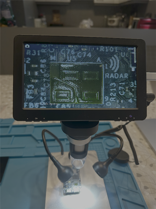
BGT60TR13C at U5The radar is at U5, under the RADAR silkscreen, with an antenna icon and the antennas etched into the PCB beside it. The package marking itself was too small to read, but the kit documentation lists the radar as the XENSIV 60 GHz BGT60TR13C, so that's the part at U5, antennas built into the board. (The gesture demo in Section 8 confirms it's populated and working.)
Figure — Radar at U5
The
RADARsilkscreen, antenna icon, and the package at U5.
S25HS512T (Cypress/Infineon Semper) — the 512-Mbit Quad-SPI NOR flash for code and data.
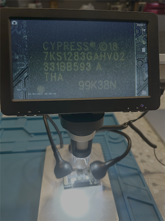
7KS1283GAHV02 (Cypress/Infineon, S27KS family) — the 128-Mbit Octal HyperRAM (PSRAM), the fast external working memory the processor and graphics path draw on.
Figure — FlashRAM
S25HS512TFigure — HyperRAM
7KS1283GAHV02.
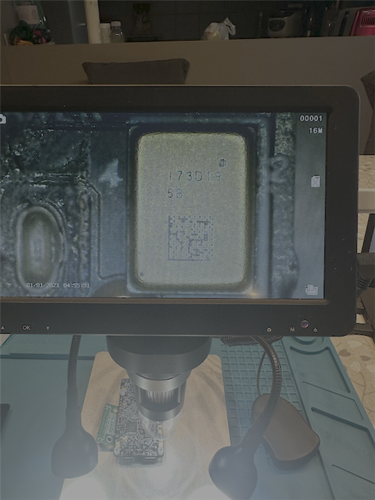
DAC3100 with the TI mark — the Texas Instruments TLV320DAC3100, a stereo audio DAC with integrated headphone/speaker amplifier: the output side of the board's audio path
Figure — Audio DAC
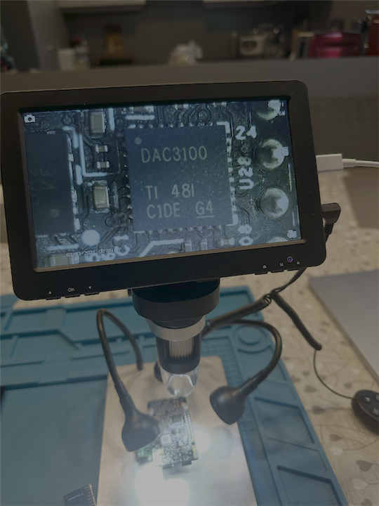
DAC3100(TI).
The kit's camera is a separate module rather than a part on the main board: an OmniVision OV7675 0.3 MP (photographed in the unboxing above).
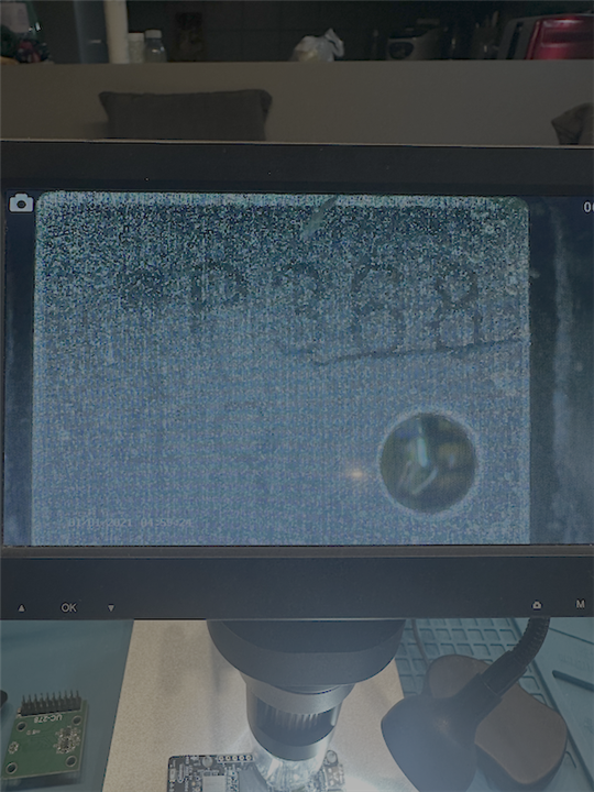
DPS368A small sensor carrying the marking DPS368
Figure — DPS368
The barometric pressure sensor, DPS368
One of the board's MEMS microphones, identified under the scope by its circular acoustic port. The kit carries two PDM microphones — the pair the Voice Assistant demo (Section 7) uses — and the package marking isn't legible in the capture, so this is recorded by its port rather than a part number.
Figure — MEMS microphone
The acoustic port of one of the onboard mics.
| Marking (read on the chip) | Part | Role | Confirmed by |
|---|---|---|---|
PSE846GPS2DBZC4A |
PSOC Edge E84 MCU (M55 + M33 + Ethos-U55 NPU + 2.5D GPU) |
Main application / AI processor | Photo + kit docs + BSP |
CY8C5868LTI-LP039 |
Cypress/Infineon PSoC 5LP | KitProg3 — onboard debugger + USB-UART | Photo + kit docs + COM5 enumeration |
SS4D27002 / 2FY + Murata |
Murata Type 2FY (LBEE5HY2FY), AIROC CYW55513 |
Wi-Fi + Bluetooth (BLE 5.4) | Photo + kit docs + BSP |
U5 (silkscreen RADAR) |
XENSIV BGT60TR13C 60 GHz radar |
Touchless gesture sensing | Location from photo; part from kit docs; working in demo |
S25HS512T |
Cypress/Infineon Semper NOR flash |
512-Mbit Quad-SPI NOR (code/data) | Photo + kit docs + BSP |
7KS1283GAHV02 |
Cypress/Infineon HyperRAM (S27KS family) | 128-Mbit Octal HyperRAM (working RAM) | Photo + kit docs + BSP |
DAC3100 (TI) |
TI TLV320DAC3100 | Audio DAC + amplifier | Photo |
OV7675 (module) |
OmniVision OV7675 | 0.3 MP bundled camera | Photo + kit docs |
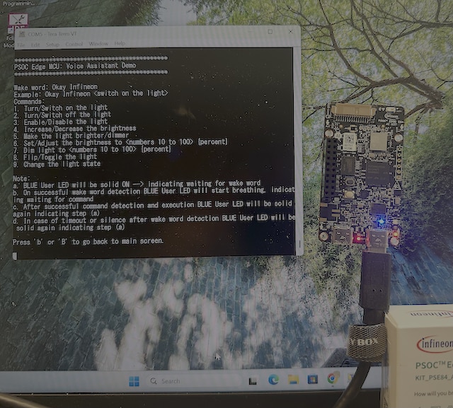
From the boot menu I selected the Voice Assistant. The demo announces itself as "PSOC Edge MCU: Voice Assistant Demo," with the wake word "Okay Infineon" and a fixed command set aimed at controlling a light — on/off, enable/disable, brighter/dimmer, set brightness to a percentage, toggle, and change state. The blue user LED tracks the interaction: solid while waiting for the wake word, then breathing once the wake word is caught and it's listening for a command, and solid again after the command runs.
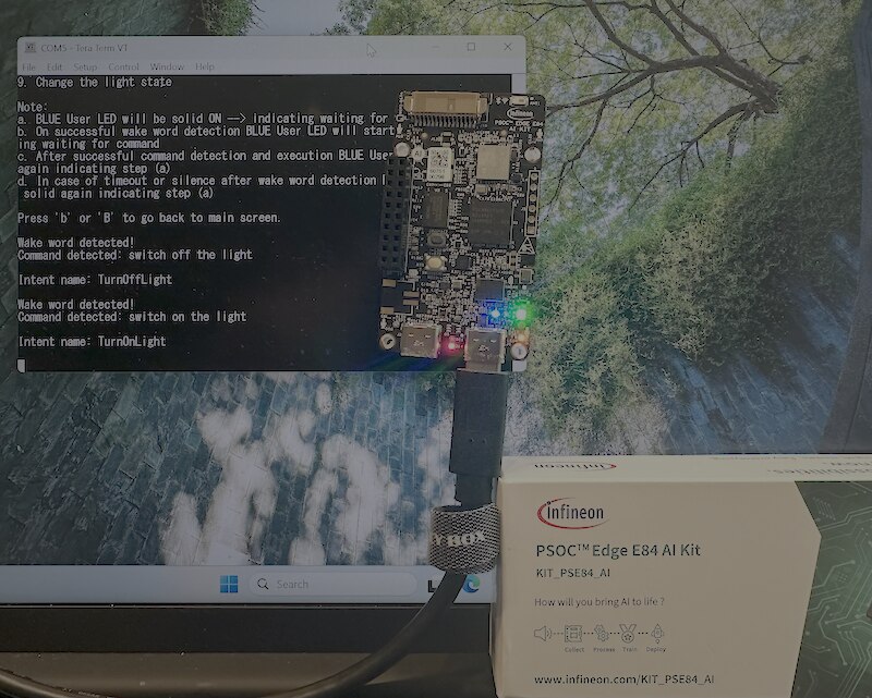
In use, the demo caught the wake word and resolved each spoken command to a named intent, printed live in the terminal. For example, "switch on the light" resolved to TurnOnLight, "switch off the light" to TurnOffLight, and "change the light state" to ToggleLight — each shown as a "Wake word detected! / Command detected / Intent name" block as I spoke. The voice path exercises the board's onboard PDM microphones identified in the teardown.
Figure — Voice assistant demo
The command list and wake-word prompt.
Figure — Commands recognized
The terminal showing detected commands and their intents, with the user LED lit.
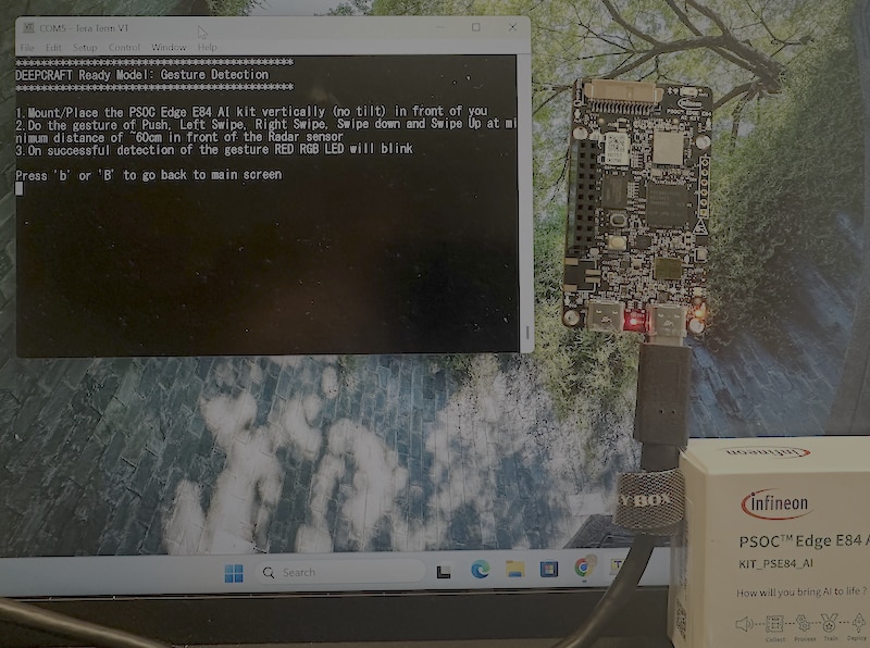
The second demo is gesture detection, which the terminal identifies as a DEEPCRAFT Ready Model. Its on-screen instructions are to stand the board vertically (no tilt) and perform Push, Swipe Left, Swipe Right, Swipe Up, or Swipe Down at roughly 60 cm in front of the radar, with the RGB LED blinking red on a successful detection.
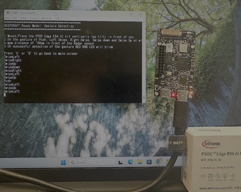
Running it, the board recognized the push and all four swipe directions, printing each one to the terminal as I performed it — a continuous stream of SwipeLeft, SwipeRight, SwipeUp, SwipeDown, and Push lines. Because the sensing is done by the radar at U6, the demo runs with nothing else attached, which also confirms the radar is populated and working on the board.
Figure — Gesture demo instructions
The DEEPCRAFT Ready Model gesture screen.
Figure — Gestures recognized
The terminal log of detected gestures.
Infineon's development flow uses two pieces: ModusToolbox (the embedded toolchain and Eclipse-based IDE) and DEEPCRAFT Studio (the Edge AI / ML model tooling). Both are installed through the Infineon Developer Center, and the one prerequisite is a free myInfineon account — I had to register before the downloads would start. I chose the standard installation.
The install. ModusToolbox is installed via its setup tool (ModusToolbox Setup 1.4), which pulls the standard package set automatically:
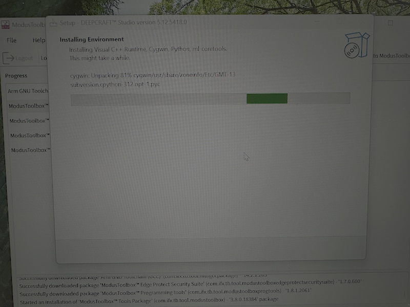
and Multi-Sense Pack 1.5.0DEEPCRAFT Studio (version 5.12) installs alongside and sets up its own environment — Visual C++ Runtime, Cygwin, Python, and ml-coretools — which is the slower part of the process (the installer warns it "might take a while").
First project — choosing the BSP. In Eclipse for ModusToolbox, the Project Creator (2.70) walks you through selecting a board support package. The board is listed under PSOC Edge BSPs as KIT_PSE84_AI (device PSE846GPS2DBZC4A, LBEE5HY2FY Wi-Fi/BT). Usefully, the BSP's own description doubles as a confirmation of the teardown — it lists the same PSE846GPS2DBZC4A MCU, 512-Mbit QSPI flash, 128-Mbit Octal RAM, LBEE5HY2FY module, KitProg3, R-Pi-compatible MIPI-DSI, analog and digital microphones, 6-axis IMU, 3-axis magnetometer, pressure and humidity sensors, and radar.
The example library. What stands out is the breadth of ready-made template applications offered for this board, grouped by area:
The factory voice and gesture demos I ran earlier correspond to the DEEPCRAFT "ready model" examples in this list, so the path from "the demo that shipped on the board" to "the same thing as a project I can open and modify" is clear.
Figures — Tooling 1
ModusToolbox Setup downloading the toolchain
Figures — Tooling 2
DEEPCRAFT Studio installing its environment
Figures — Tooling 3
Project Creator with the KIT_PSE84_AI BSP
To check the full development loop — not just installing the tools but getting something onto the board — I created and ran the Hello World example.
Starting Project Creator in Eclipse for ModusToolbox, the connected board was auto-detected (listed under "Detected Devices" as KIT_PSE84_AI), so I didn't have to choose the BSP manually. From New Application → Getting Started I selected PSOC Edge Hello World, a simple example that prints a "Hello world" message over UART and blinks a user LED from the Cortex-M33.
One thing this example makes clear is the architecture of a PSOC Edge E84 application. Each app has a dual-CPU, three-project structure: a CM33 secure project (SPE), a CM33 non-secure project (NSPE), and a CM55 project. At reset a secure boot flow runs from ROM with the device's secure enclave as the root of trust, hands off to the secure CM33, then to the non-secure CM33 — which initialises clocks, pins, and the retarget-io UART — which in turn enables the CM55. The debug UART reaches the PC through the KitProg3 virtual COM port, and User LED1 blinks once a second.
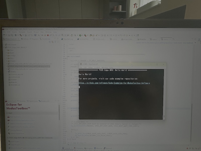
I built the project (toolchain validation passed, GCC_ARM), programmed it to the board over KitProg3, and opened Tera Term on COM5. The terminal showed the expected output:
*************** PSOC Edge MCU: Hello world ***************
Hello World!
For more projects, visit our code examples repositories:
https://github.com/Infineon/Code-Examples-for-ModusToolbox-Software
So the complete flow — install → auto-detected BSP → create project → build → flash → verify on the terminal — works end to end. The DEEPCRAFT machine-learning examples (Section 10) are the natural next step from here.
Figures — Hello World
The auto-detected BSP; the Hello World template selected; the example open in the editor; and the "Hello World!" output in Tera Term.
Part 1 took the kit as far as it goes on the bench: unboxed, torn down, demoed, and running my own first project. Part 2 (below) takes the same board off the bench entirely and turns it into a self-contained, solar-powered, air-gapped Edge AI node — the Doomsday Cyberdeck.
The plan adds four things to the board — a 4.3-inch MIPI-DSI display, an OPEN-SMART SPI microSD card, a Rii 518BT Bluetooth keyboard (with physical buttons as the robust fallback), and a 3000 mAh+ protected LiPo with solar charging — so the device boots from its own battery, recharges from the sun, shows its own dashboard, keeps its own logs, and runs its AI with no PC, no mains, and no network.
Edge E84 AI Kit RoadTest — Part 2What this part is. A build plan, not a finished build. Everything below is design intent and the open questions I still have to settle on the bench — nothing here is reported as a tested result. Part 1 covered the kit as it ships (teardown, factory demos, toolchain, a first project). This part takes the same board off-grid.
The premise is simple: take the PSOC Edge E84 AI Kit and turn it into a device that needs nothing else — no PC, no wall power, no network. A single board that boots from its own battery, recharges from the sun, shows what it's doing on its own screen, takes input from its own keys, keeps its data on its own card, and runs its AI entirely on-device. A self-contained edge-AI node you could set down anywhere and leave running.
This is what I'm calling the doomsday cyberdeck — "doomsday" in the sense of fully self-reliant and air-gapped, not as a gimmick. The design target is an instrument that keeps sensing, deciding, and logging when there is no cloud, no Wi-Fi, and no mains.
The E84 is a surprisingly good fit for this:
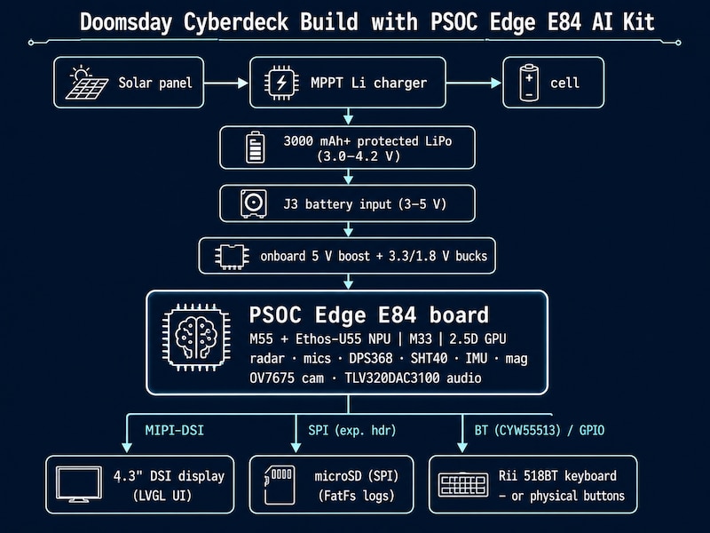
The board is the brain and the sensor array; the four added parts give it a face (display), a memory (microSD), hands (keyboard/buttons), and a heart that never needs the wall (solar + battery).
| # | Part | Role | Interface to the board |
|---|---|---|---|
| — | PSOC Edge E84 AI Kit |
Compute + sensing core | — |
| 1 | 4.3-inch MIPI-DSI display | On-device screen / UI | MIPI-DSI connector (R-Pi-compatible) |
| 2 | OPEN-SMART microSD breakout | Local mass storage | SPI on the expansion I/O header |
| 3 | Rii 518BT Bluetooth keyboard | Input / navigation | Bluetooth (CYW55513) |
| 4 | 3000 mAh+ protected LiPo + solar panel + Li solar charger | Off-grid power | Cell → J3 (3–5 V); solar → charger → cell |
Role. The deck's face. Instead of a serial console on a laptop, the unit renders its own dashboard: current mode, live sensor readings, AI output, alerts, and battery/solar status.
Connection. The board exposes an R-Pi-compatible MIPI-DSI connector (confirmed in the BSP description in Part 1), which is the intended path for a 4.3-inch DSI panel. The E84's 2.5D GPU drives the display, and the LVGL graphics example ("PSOC Edge Graphics LVGL Demo", plus the single/double-buffering example) is the starting point for the UI.
UI plan. An LVGL layout with a status header (mode, battery, solar in/out), a live sensor panel (pressure trend, temp/humidity, compass heading, radar presence), an AI-output area (voice intent / vision result), and a few menu screens the keyboard or buttons can drive.
Power. Roughly 1.0–1.3 W with the backlight on — the backlight dominates, so PWM dimming and blanking the panel when idle are the main power levers.
Open question. 4.3-inch DSI panels differ in resolution (commonly ~480×800 or 800×480) and in the DSI bridge/controller they use. The panel has to either match what the PSOC Edge graphics stack already supports or need a panel-init/driver written for it. Confirming panel compatibility is the first display task.
Role. Mass storage for an off-grid node: time-series sensor logs, captured events (audio/radar/vision), AI model files, and offline reference data (maps, field guides, manuals) that can be browsed on the display. The onboard 512-Mbit QSPI flash is tiny by comparison; a microSD card adds gigabytes of removable, non-volatile storage.
Connection. The OPEN-SMART breakout is a plain SPI SD-card adapter. It wires to the board's SPI on the expansion I/O header — SCK, MOSI, MISO, CS, plus 3V3 and GND (exact pins per the BSP pin map). The card runs in SPI mode with a FatFs filesystem (FAT32), so a card pulled from the deck reads on any PC.
Log format (illustrative). A field-logging record might look like:
timestamp,mode,channel,value,unit,note
000001,env,pressure,1007.2,hPa,
000002,env,humidity,57.0,%RH,
000003,radar,presence,1,,approach@~1m
000004,voice,intent,TurnOnLight,,wake=OkayInfineon
000005,power,battery,3.91,V,solar=charging.For input I have two paths, and for a self-reliant device the robustness trade-off matters more than comfort.
Rii 518BT over Bluetooth. The board's AIROC CYW55513 (BLE 5.4 + Classic BT) would act as a Bluetooth HID host, accepting the keyboard's key (and touchpad) events. This gives full text entry and a pointer — nice for menus and labels.
Open question — this is the biggest software unknown in the build. Receiving a keyboard requires a BT HID host profile on the device side; having the radio is not enough. Infineon's AIROC BT examples lean toward HID device and specific profiles, so HID host support has to be confirmed. It also depends on how the Rii 518BT pairs: a BLE HID (HOGP) host is far more tractable than a Classic-BT HID host. This gets validated before anything is built on top of it.
The voltage works out nicely. The board has a battery input — connector J3, rated 3–5 V — that takes a single lithium cell directly, and the board makes its own 5 V / 3.3 V / 1.8 V rails from that input via the onboard boost and bucks. A LiPo at 3.0–4.2 V sits right in range, so no separate boost-to-5 V module is needed. The one catch (from Part 1): J3 is an unpopulated rework header, so a JST connector has to be soldered to it first.
The cell. A 3000 mAh+ protected LiPo — protected meaning an over-/under-voltage and over-current PCB on the pack (essential for an unattended, solar-charged device).
Solar. A small panel (e.g., 6 V, ~2–5 W) feeds a Li-ion solar charge controller — an MPPT-class charger such as a CN3791 or CN3065 is a better match for a solar source than a plain TP4056, because it holds the panel near its maximum-power point. The controller does CC/CV charging to 4.2 V; the protected cell is the safety backstop. Charging-while-running needs a load-sharing arrangement so the deck can draw from the panel and top up the cell at the same time.
Power budget (estimate — to be measured on the bench):
| Subsystem | Approx. draw |
|---|---|
| Board: M55 + NPU + M33, radar, mics | ~0.6–0.8 W |
| 4.3" display + backlight | ~1.0–1.3 W |
| microSD writes + Bluetooth link | ~0.2 W |
| Total, screen on + AI + radar active | ~2 W (≈0.5–0.7 A at the cell) |
Runtime and the solar question. At ~2 W continuous, a 3000 mAh cell gives roughly 4–5 hours before a safe cut-off. But a doomsday node should rarely run flat-out: with the M33 awake for always-on sensing and the M55 + display gated (radar/voice wake the heavy compute only on an event), average draw can fall to a fraction of a watt, stretching the cell to days.
Sustained ("indefinite") operation is then a solar-harvest-vs-load equation, and I'd rather give the math than a promise:
So the design rule is: aggressive duty-cycling + event-driven wake is what makes the solar path actually self-sustaining. Panel wattage and real-world sun hours then size the margin.
Open questions. Mounting the J3 connector; getting the load-sharing path right so it runs while charging; and sizing the panel against the chosen duty cycle and local sun. Thermal is also on the list — M55 + NPU + display under load inside a sealed enclosure needs either headroom or duty-cycling.
Every mode below runs on-device, using sensors already on the board — no network. This is where the E84's NPU and sensor suite pay off for an off-grid node:
Everything surfaces on the 4.3" LVGL dashboard, is driven by keyboard, persists to microSD, and is powered by solar + battery — with radios off (true air-gap) except for the optional Bluetooth keyboard.
A 3D-printed rugged case housing the board, the display (front window), the battery, the charger, and the button cluster, with the solar panel on the lid or on a short lead. Ports/cutouts for the panel input, the USB-C (J1, for charging/programming when available), and microSD access. The design has to balance ruggedness against the thermal need for some airflow under AI load.
The concept is settled; these are the real unknowns the build has to resolve, in rough order of risk:
Edge E84 AI Kit RoadTest — PSOC, XENSIV, AIROC, DEEPCRAFT, ModusToolbox are trademarks of Infineon Technologies.