RoadTest: Test out Arduino's Uno Q - The new Single-Board Computer!
Author: Shishir
Creation date:
Evaluation Type: Development Boards & Tools
Did you receive all parts the manufacturer stated would be included in the package?: True
What other parts do you consider comparable to this product?: Raspberry Pi, Banana Pi, Hybrid systems(SBC+MCU)
What were the biggest problems encountered?: Understanding the concept and working of dual brain architecture and how things were being executed under the hood. The new feature of creating custom bricks is also a bit hard and needs more documentation.
Detailed Review:
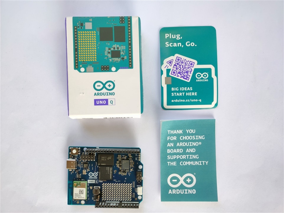
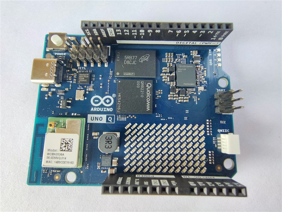
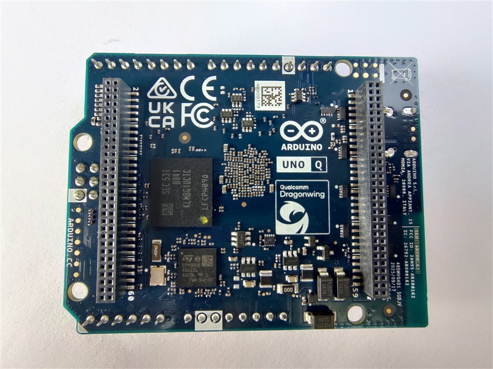
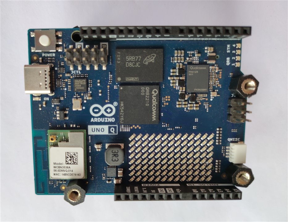
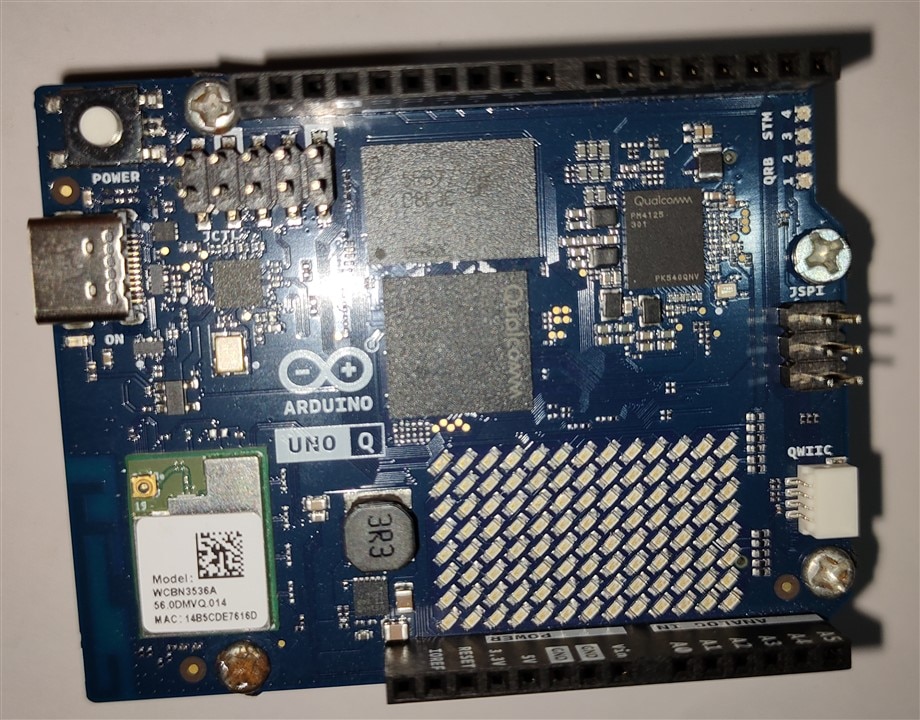
The Arduino UNO Q is a hybrid system containing Qualcomm's Dragonwing QRB2210 MPU which comes with Debian Linux and an STM32U585 microcontroller running Zypher OS, a real time OS on the same board. Unlike normal Arduino boards, this hybrid allows both high-level Linux applications and real-time microcontroller code to work simultaneously and communicate with each other through the built-in RPC (Remote Procedure Call) bridge. This allows a Python script running on the Linux MPU to seamlessly request data from an Arduino sketch running on the MCU, and vice versa, without writing complicated serial protocols.
The Microprocessor Unit(MPU) handles heavy data computations, running Python scripts, executing AI machine vision models, and controlling Wi-Fi or Bluetooth stacks.
The Microcontroller Unit(MCU) does the deterministic, real-time hardware control i.e. where precise timing and minimum delay is required.
This architecture addresses a common problem encountered in many embedded projects. When using a traditional SBC, direct analog input capability, pwm etc. absent, requiring additional ADC hardware or a microcontroller to be used as a middleware. Conversely, while microcontrollers excel at real-time hardware control, they lack the computational power and software ecosystem available on Linux. The UNO Q attempts to combine the strengths of both approaches into a single development platform.
| {gallery}Overview |
|---|
|
Overview |
|
Front |
|
Back |
The board consists of two major processing domains:


One of the key advantages of the Arduino Uno Q is that analog peripherals remain directly accessible through the MCU while Linux applications can access them through RPC.
Another important consideration when working with the UNO Q is the presence of different voltage domains. The STM32 microcontroller operates using 3.3V GPIO logic, while the high-speed expansion headers connected to the SBC side operate at 1.8V logic levels. Care must therefore be taken when interfacing external hardware.
The board supports multiple power input methods, including USB-C power and a 7–24V DC input, increasing deployment flexibility in embedded applications.
| {gallery}My Gallery Title |
|---|
|
Input power options |
|
Power block diagram |

UNO Q supports dual power inputs: a USB-C port and a 7-24V DC input. Over USB Power Delivery, it requests only the 5 V / 3 A contract and does not request higher-voltage PD profiles. Use a supply and cable rated for 5 V at 3 A to avoid undervoltage during short activity peaks such as wireless bursts or display initialization. A regulated external 5 V DC source can also be used to supply power to the board via the 5 V pin on the JANALOG header.
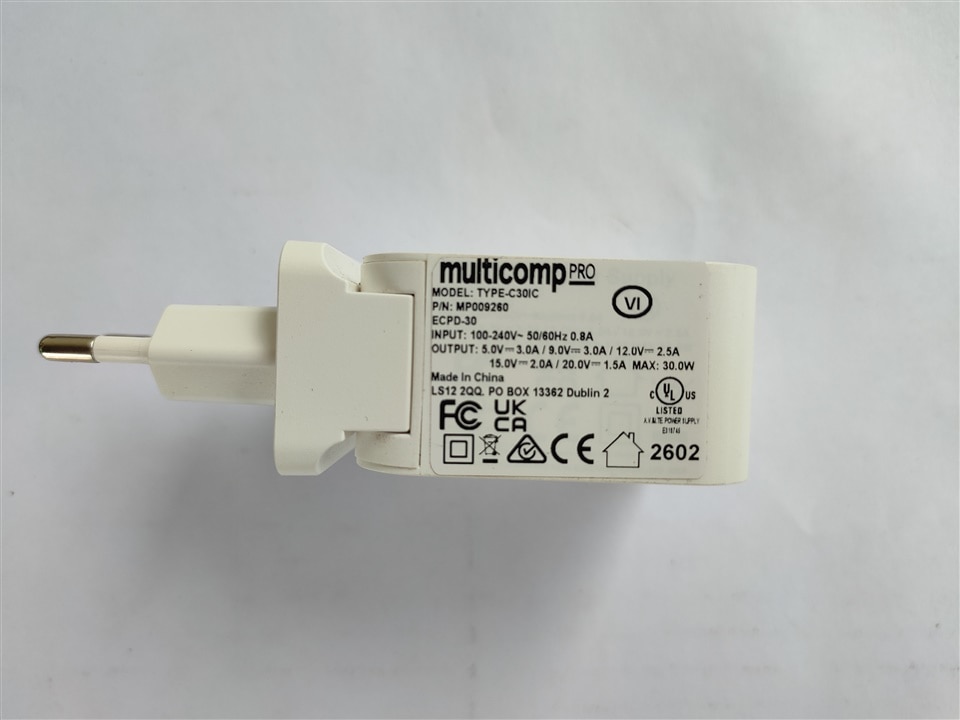
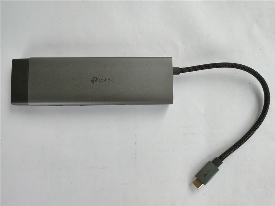
For proper power supply and connectivity, a Multicomp Pro travel adaptor(with three different region pins) (5V/3A, 9V/3A, 12V/2.5A, 15V/2A, 20V/1.5A ; Max 30W), a 240W ERP(Extended Power Range) cable and a TP link USB type C 9-Port hub(also used for SBC mode) was also provided for this roadtest.
| {gallery}Power adaptor and cable |
|---|
|
Adaptor |
|
Cable |
|
Type C Hub |
Through the USB-C VBUS Connector the board communicates via USB Power Delivery (PD) but specifically requests a 5 V / 3 A contract only. It does not request higher-voltage (9 V/12 V/20 V) profiles.
USB-C VBUS and the 5 V output of the 7-24 V buck are diode-OR combined onto the system 5 V bus (5V_SYS). From 5V_SYS, the design derives the 3.8 V pre-regulator node and, subsequently, the 3.3 V. The PMIC, powered by 5V_SYS, derives the 1.8V rail.
The Diode-OR circuit is designed to connect multiple inputs so that if one fails, the other takes over instantly without dropping power to the board. Diode Oring also provides reverse polarity protection as the diode on the lower-voltage source becomes reverse-biased, preventing power from back-feeding into that source.
The Arduino Uno Q features a built-in 8x13 (totaling 104 individual LEDs) LED matrix on its surface. Instead of wiring up hundreds of pins or using a massive external driver chip, Arduino engineered this matrix using a highly efficient circuit design trick called Charlieplexing.

Charlieplexing is an advanced electronic multiplexing technique that utilizes the tri-state logic of microcontroller pins to control a massive number of LEDs using very few input/output (I/O) pins. Standard digital pins only have two states: HIGH (5V/3.3V) and LOW (GND). Microcontrollers like the Uno Q's STM32 have a hidden third state: High-Impedance (INPUT mode). In this third state, the pin acts as an open switch or an "invisible" wire, meaning no electricity can flow in or out. By exploiting this third state and connecting pairs of LEDs in parallel with opposite polarities (back-to-back), we can selectively light up one specific LED while leaving all others completely disconnected.
The mathematical formula for Charlieplexing is:
Max LEDs = N X (N-1)
(Where N is the number of microcontroller pins used)
To control 104 LEDs individually using standard matrix rows and columns, we would normally need 8 + 13 = 21 dedicated pins. With Charlieplexing, because 11 × (11 - 1) = 110, the board only needs 11 pins from the STM32 MCU to address the entire 104-LED display. By condensing 104 LEDs down to just 11 physical lines internally, the board avoids consuming all of its own GPIO header pins. That leaves us plenty of free analog and digital pins left over to connect with our own sensors, motors, and shields.
.ino) running on a real-time operating system (Zephyr OS) on the STM32 microcontroller. This handles low-latency hardware, PWM, timers, and sensor reading.app.yaml file defines the metadata, hardware permissions, and startup configurations of the dual-system application.| {gallery}App Lab |
|---|
|
Board Not Detected |
|
Board Detected |
>_) straight into the Uno Q's Linux environment (arduino@unoq).The initial setup was short and simple, we are required to connect the arduino uno q to the computer and after being detected we set wifi credentials and username / password for our sbc. After the first setup the board automatically updates itself.
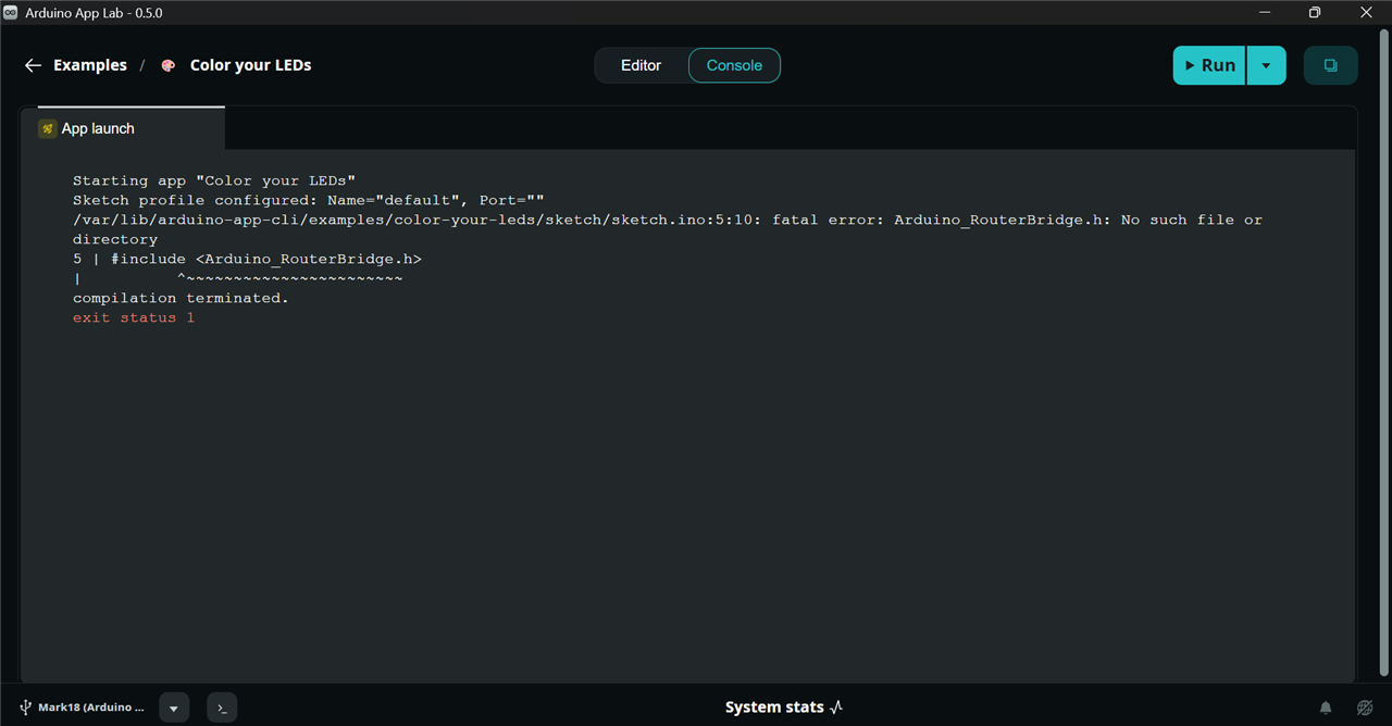
One issue I faced before updating App Lab was that the offline examples threw errors after uploading. However, once I updated both Zephyr packages and App Lab to the latest version, the issue was resolved. The updated App Lab interface was also noticeably improved compared to earlier releases, with a cleaner layout and more accessible logging functionality.
The first test performed was the classic LED blink program. Although simple, it serves as a useful verification of the complete upload chain and confirms that the STM32 subsystem is functioning correctly.

The sketch uploaded successfully and operated as expected, confirming reliable communication between the development environment and the microcontroller.
Usually, from App Labs, we run applications written as Python scripts on the microprocessor, which interact with the microcontroller running the .ino sketch. The microcontroller comes preloaded with firmware that continuously listens for requests from the microprocessor and responds when invoked through the RPC bridge. However, the microcontroller section of the UNO Q can also be programmed independently, just like a standard Arduino Uno. The microcontroller used on the UNO Q is the STM32U585.
To program the microcontroller, we need Arduino IDE version 2.3.6 or later. In the Arduino IDE:
An interesting observation is that, once Wi-Fi has been configured, the Arduino UNO Q appears as both a standard physical COM port and a Network Port in the Arduino IDE, provided that the board and the laptop are connected to the same network. 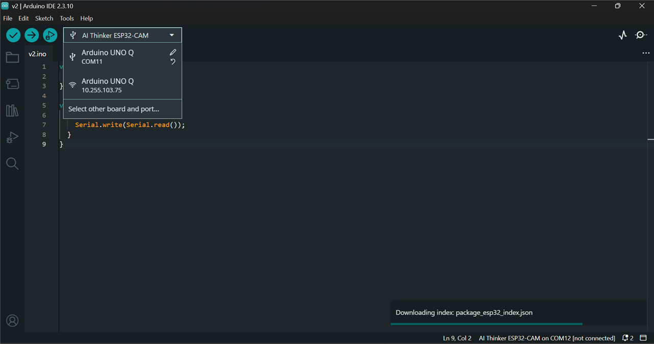
Now we can upload simple blink sketch:
void setup() {
  pinMode(LED_BUILTIN, OUTPUT);
}

void loop() {
  digitalWrite(LED_BUILTIN, HIGH);
  delay(1000);
  digitalWrite(LED_BUILTIN, LOW);
  delay(1000);
}
| {gallery}Code Upload |
|---|
|
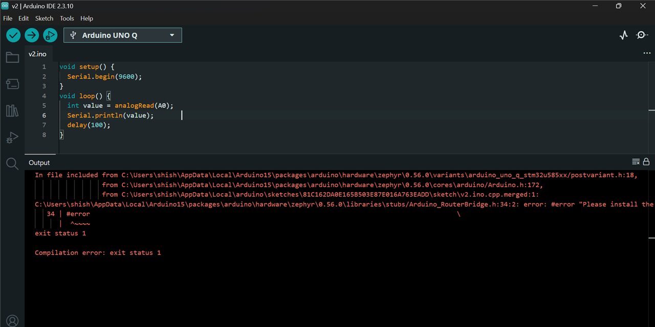
Arduino Bridge Library Not Installed |
|
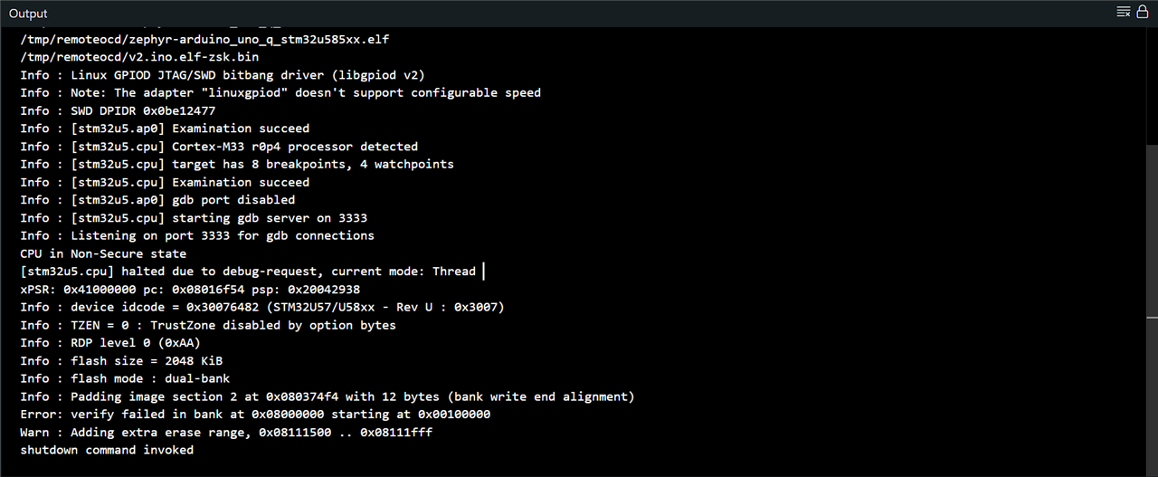
Successful Code Upload Log |
Programming traditional STM32 microcontrollers usually requires deep embedded systems knowledge. It is one of the reasons many hobbyists do not touch them easily because of their reputation of being hard to program. We need to configure register-level settings, HAL, clock configuration, use tools like STM32CubeIDE and connect debuggers like an ST-Link. The Arduino Uno Q bypasses all of this complexity by abstracting the difficult parts into the friendly Arduino ecosystem. The board package pre-configures all clocks, timers, and internal settings the moment the board boots up. If we want to use the high-performance 14-bit ADC, we do not need to initialize registers; we simply type analogRead(A0).
ADC Testing
The STM32U585 provides a 14-bit ADC.
A 10 kΩ potentiometer was connected to A0.
Initial testing produced only 10-bit values because the ADC resolution must be explicitly configured: analogReadResolution(14);
void setup() {
  Serial.begin(9600);

  analogReadResolution(14);  // To set 14bit precision
}
void loop() {
  int value = analogRead(A0);
  Serial.println(value);
  delay(1500);
}
After enabling 14-bit mode:
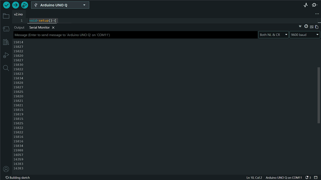
The 14-bit ADC of Arduino Uno Q gives us 16,384 distinct values, which is exactly 16 times more resolution than a standard 10-bit ADC which only gives 1,024 values.
LDR Testing
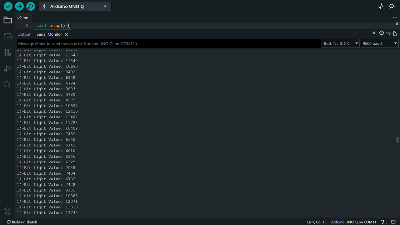
A light-dependent resistor was connected to the ADC input.
void setup() {
  Serial.begin(9600);
  analogReadResolution(14); // For full 14-bit resolution
}

void loop() {
  int ldrValue = analogRead(A0);
  Serial.print("14-Bit Light Value: ");
  Serial.println(ldrValue);
  delay(150);
}
The board correctly produced varying readings according to illumination level.
I was planning to evaluate the output of an MQ135 gas sensor using the UNO Q. However, the sensor's heater circuit requires a 5 V supply for proper operation, and I was concerned that the analog output voltage could potentially exceed the UNO Q's 3.3 V ADC input limit. To avoid any risk of damaging the board, I abandoned the MQ135 testing.
DAC to ADC Loopback
The STM32U585 includes a true hardware 12 bit DAC.
For testing the DAC, I did not had a suitable amplifier circuit available, nor was I able to build one at the time. Therefore, I looked for alternative methods to evaluate the DAC capabilities of the UNO Q. I found that the board's ADC can be used to measure the output of its own DAC, creating a simple loopback test. In this setup, the DAC output is connected to an ADC input, allowing the generated analog voltage to be read back and verified by the microcontroller. I then implemented this loopback test to evaluate the DAC's functionality and performance.
DAC (A1)
   ↓
ADC (A0)
#include <Arduino.h>
const int dacPin = A1;
const int adcPin = A0;
void setup() {
Serial.begin(9600);
while (!Serial) delay(10);
analogWriteResolution(12);
analogReadResolution(14);
Serial.println("================================================");
Serial.println(" UNO Q DAC-TO-ADC PERFORMANCE REVIEW ");
Serial.println("================================================");
}
void loop() {
int testValues[3] = {1024, 2048, 3072};
for (int i = 0; i < 3; i++) {
int targetDacValue = testValues[i];
float expectedVoltage = (targetDacValue / 4095.0) * 3.3;
analogWrite(dacPin, targetDacValue);
delayMicroseconds(50);
int rawAdcValue = analogRead(adcPin);
float measuredVoltage = (rawAdcValue / 16383.0) * 3.3;
Serial.print("DAC Setpoint: "); Serial.print(targetDacValue);
Serial.print(" | Expected: "); Serial.print(expectedVoltage, 3); Serial.print("V");
Serial.print(" ---> ADC Read (14b): "); Serial.print(rawAdcValue);
Serial.print(" | Measured: "); Serial.print(measuredVoltage, 3); Serial.println("V");
delay(2000);
}
Serial.println("------------------------------------------------");
}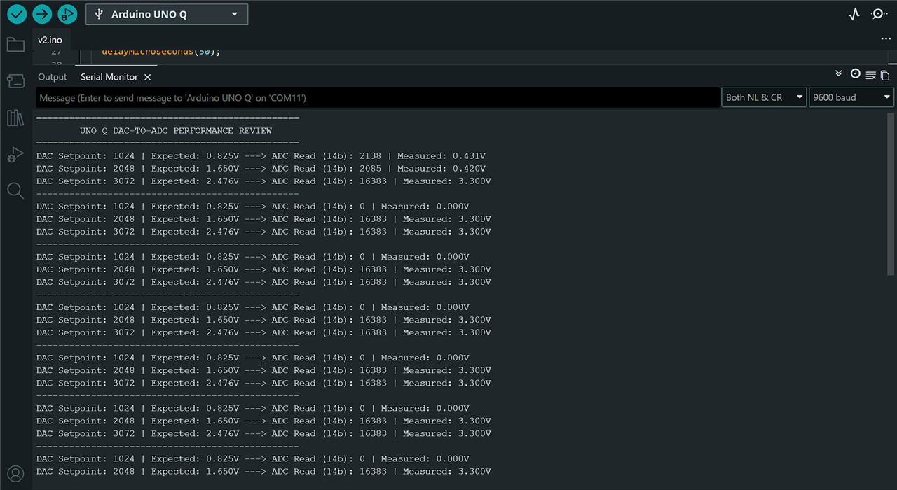
The measured voltages closely tracked the expected DAC outputs, confirming correct DAC operation.
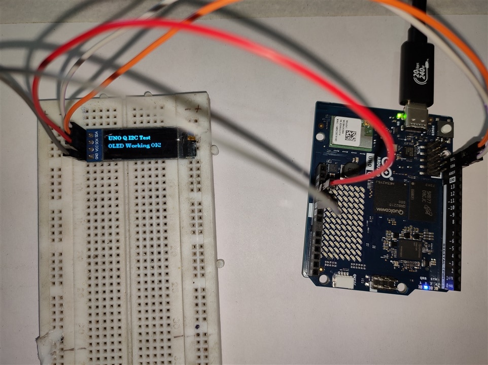
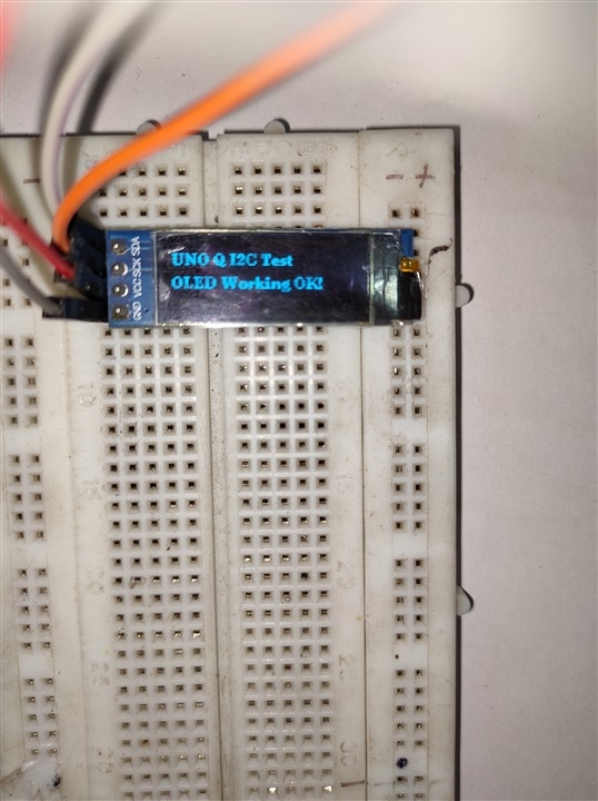
A 0.91-inch 128×32 OLED display connected with Uno Q.
Initial attempts using Adafruit SSD1306 libraries resulted in compatibility issues. The display worked correctly after switching to the U8G2 library. The U8G2 implementation is more portable and compatible with the Zephyr-based Arduino environment used by UNO Q.
#include <Arduino.h>
#include <U8g2lib.h>
#include <Wire.h>

U8G2_SSD1306_128X32_UNIVISION_F_HW_I2C u8g2(U8G2_R0, /* reset=*/ U8X8_PIN_NONE);

void setup() {
  Serial.begin(9600);

  // Initialize the screen
  u8g2.begin();
}

void loop() {
  u8g2.clearBuffer();
  u8g2.setFont(u8g2_font_ncenB08_tr);

  u8g2.drawStr(0, 12, "UNO Q I2C Test");
  u8g2.drawStr(0, 28, "OLED Working OK!");

  u8g2.sendBuffer();
  delay(1000);
}
The display successfully rendered text and refreshed normally.
| {gallery}My Gallery Title |
|---|
|
1 |
|
2 |
SG90 Servo Test
PWM functionality was tested using an SG90 servo motor. The standard Servo library did not function correctly.Instead, the dedicated Arduino_HardwareServo library was required.
#include <Arduino_HardwareServo.h>

// Create the servo instance using the correct class name
HardwareServo myServo;

void setup() {
  // Attach the SG90 servo signal wire to Digital Pin 9
  if (!myServo.attach(9)) {
    // If it fails to allocate a hardware timer channel, stop here
    while(1);
  }
}

void loop() {
  myServo.write(0);   // Sweep to 0 degrees
  delay(1000);

  myServo.write(90);  // Sweep to 90 degrees
  delay(1000);

  myServo.write(180); // Sweep to 180 degrees
  delay(1000);
}
The servo was powered from an external regulated 5 V source. Initially no movement occurred. The issue was resolved after I remembered that a common ground between the UNO Q and the external power supply needs to be made to set a reference between the two.
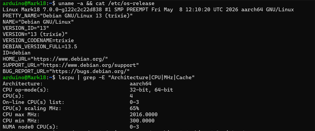
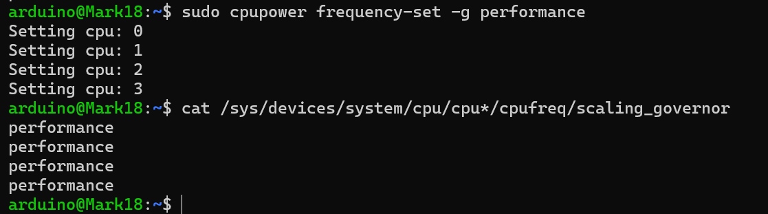
While the microcontroller handles real-time peripherals, the SBC side is responsible for Linux workloads. The Governor is Linux kernel driver that depends the speed and performance control of processor cores. It dynamically manages the operating frequency based on workload, increasing frequency when heavy load is detected and reducing speed on low load to conserve power and maintain temperature. The term governor is taken from the physical governor that were earlier used in automobiles to keep the engine speed constant. Governor has different modes for different purpose:
1. performance: Locks the CPU at its maximum rated speed permanently. It never drops down, even if the system is idle.
2. userspace: Kernel stops managing the CPU speed automatically, it allows a user with root privileges (or a specific background daemon) to manually set and lock the CPU to a specific, fixed frequency.
3. ondemand: Dynamically adjusts the CPU speed depending on how hard the system is working, constantly checks the CPU usage. If the workload hits a certain threshold, it instantly jumps the CPU to its maximum clock speed. As the workload decreases, it slowly lowers the clock speed back down.
4. schedutil: The modern standard. Unlike ondemand, which guesses workload by looking backward at CPU utilization statistics, It integrates directly with the Linux kernel scheduler. It calculates the exact frequency needed to handle current tasks smoothly
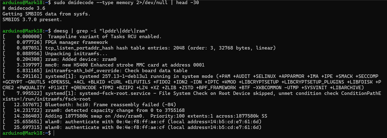
For benchmarking purpose and measuring raw speed, we require the governor to be in performance mode. After setting it, following are the benchmarks to analyze the performance
| {gallery}Versions, Governor and other stats |
|---|
|
OS version, Cpu details |
|
Setting Governor to performance |
|
|
 |
Single-thread result:
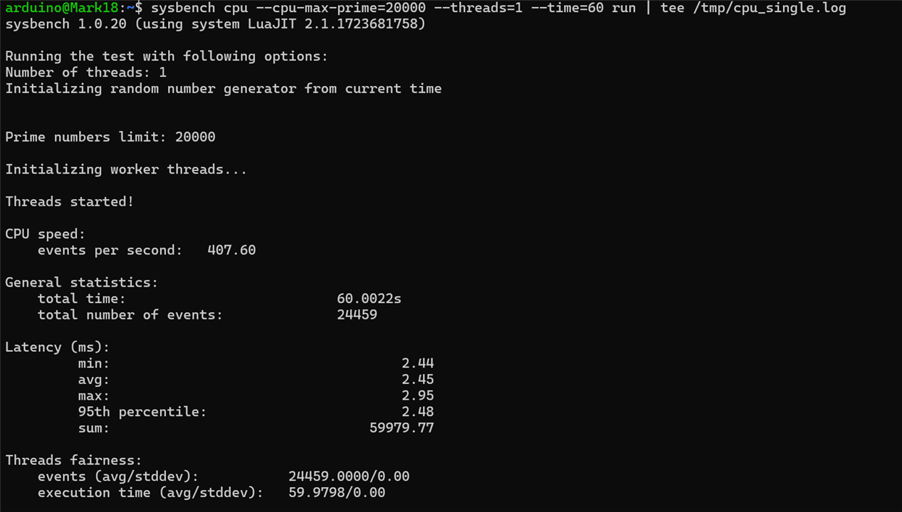
407.60 events/secMulti-thread result:
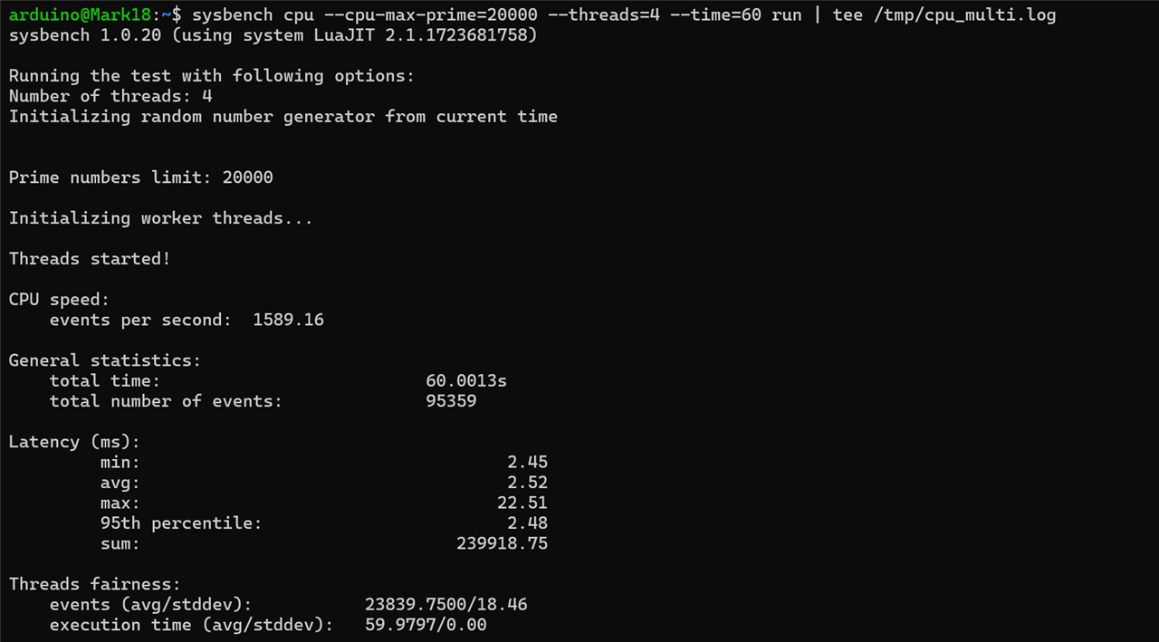
1589.16 events/secPerformance scaling was close to four times the single-thread result, indicating efficient utilization of all available CPU cores.
Single-thread total rating:
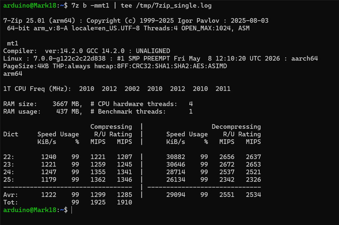
1910 MIPSMulti-thread total rating:
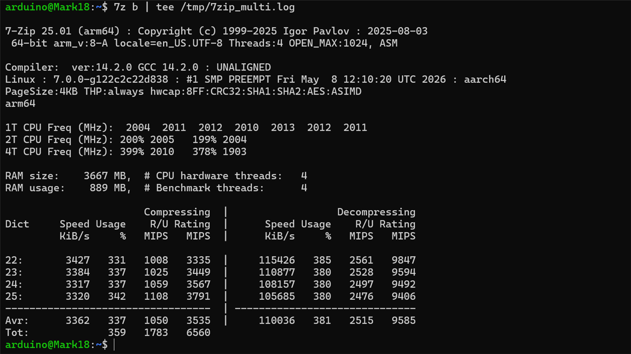
6560 MIPS
The substantial increase in performance under multi-threaded operation further demonstrates the effectiveness of the quad-core Cortex-A53 architecture.
Key Scores:

Used dd utility to evaluate storage throughput
Write test:

602 MB/sRead test:

1.6 GB/sSo this indicate that storage throughput is not likely to become a bottleneck for typical SBC applications.
AES-256

~942 MB/sSHA-256

~837 MB/sRSA-2048

Sign: 185 ops/sec
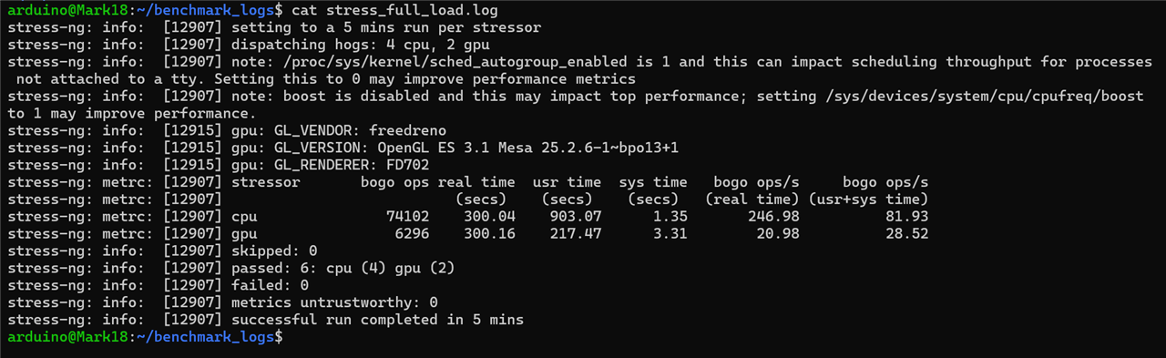
Verify: 6862 ops/secThis test evaluates the system stability and thermal dissipation capabilities of the Arduino Uno Q SBC Qualcomm MPU. The Arduino Uno Q has 10 hardware thermal zones to closely monitor heat layout across different parts.

I selected zones 0,3,4 and 7 to focus on CPU and GPU
stress-ng --cpu 4 --cpu-method all --gpu 2 --timeout 300s --metrics-brief 2>&1 | tee ~/benchmark_logs/stress_full_load.log
while true; do t0=$(awk '{print $1/1000}' /sys/class/thermal/thermal_zone0/temp); t3=$(awk '{print $1/1000}' /sys/class/thermal/thermal_zone3/temp); t4=$(awk '{print $1/1000}' /sys/class/thermal/thermal_zone4/temp); t7=$(awk '{print $1/1000}' /sys/class/thermal/thermal_zone7/temp); echo "$(date '+%H:%M:%S') | MAPSS: ${t0}°C | CPU0: ${t3}°C | CPU1: ${t4}°C | GPU: ${t7}°C" | tee -a ~/detailed_thermal_log.txt; sleep 2; done

| Evaluation Phase | MAPSS (Zone 0) | CPU0 (Zone 3) | CPU1 (Zone 4) | GPU (Zone 7) | ||
| Idle Baseline | 39.1°C | 41.0°C | 41.3°C | 38.8°C | ||
| Stress Peak Max | 62.4°C | 68.9°C | 68.3°C | 60.8°C | ||
| Sustained Delta | +23.3°C | +27.9°C | +27.0°C | +22.0°C | ||
| Cool-Down Baseline | 37.9°C | 39.1°C | 38.5°C | 37.9°C |
I did the test without heatsink or any active cooling.
| {gallery}My Gallery Title |
|---|
|
|
|
|
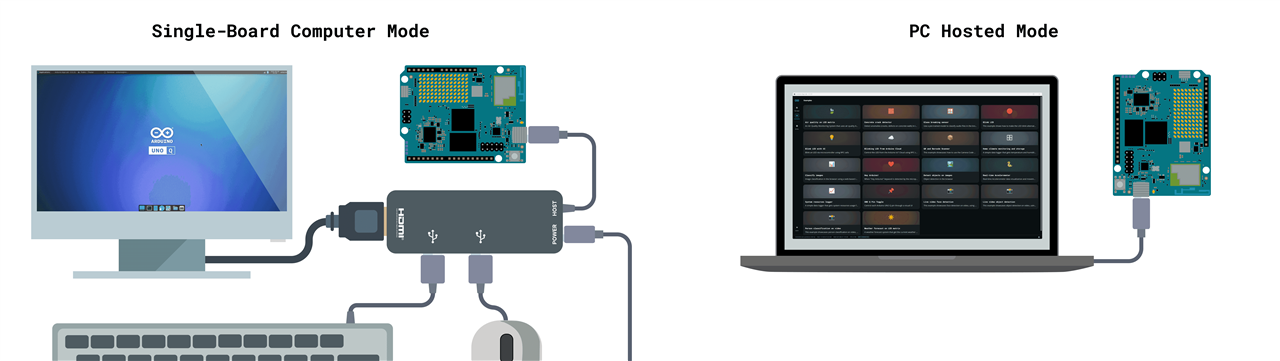
Essentially the Arduino Uno Q can be used in three ways or configurations: being connected with desktop, remote desktop and stand alone single board computer.
This is the default out-of-the-box configuration and is highly recommended for first-time setup and initial prototyping. In this mode, Arduino App Lab is installed directly on a laptop or desktop computer, and the UNO Q is connected via its USB Type-C interface. After the initial Wi-Fi and credential setup, the board can also be accessed wirelessly through network mode using App Lab.
In this configuration, the desktop handles the computationally intensive tasks, such as compiling Arduino sketches and processing Python scripts. When the Run button is pressed, App Lab uploads the compiled firmware to the STM32 microcontroller over USB while simultaneously launching the companion Python applications on the Linux-powered Qualcomm microprocessor.
This is the simplest operating mode, requiring only a single USB cable to connect the UNO Q to a desktop or laptop computer.
Once the initial configuration is complete, the physical connection between the desktop and the UNO Q can be completely removed while retaining full programming and management capabilities. After the board is provided with the local Wi-Fi credentials, it becomes an active node on the local network through mDNS discovery. Arduino App Lab then connects securely to the board over the network using an automated SSH connection. This mode provides true desktop freedom, allowing the UNO Q to remain mounted inside a robotics chassis, installed in an automation panel, or placed elsewhere in the workspace while still being fully accessible from a laptop or desktop computer.
Firmware updates can be uploaded to the microcontroller, Python applications can be deployed, and AI models can be modified without requiring a direct USB connection.
This mode is particularly useful for hackathons, demonstrations, events, and projects where quick remote access to the board is important. It also eliminates the hassle of carrying extra cables and repeatedly connecting and disconnecting the board from a computer.
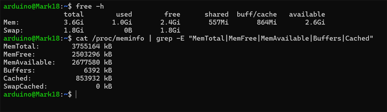
In this configuration, the Arduino UNO Q moves beyond the traditional "development board" role and functions as a full-fledged Linux desktop computer. For this use case, the 4 GB RAM variant is recommended.
The board is powered using a dedicated 5 V / 3 A USB Power Delivery supply. To expand its connectivity, a USB-C hub is connected to the Arduino UNO Q. Using the hub's power pass-through feature, the board can be powered while simultaneously taking advantage of its multi-role USB-C interface for additional USB peripherals and Ethernet connectivity. Thanks to the onboard ANX7625 bridge chip, the UNO Q's USB-C port also supports DisplayPort Alt Mode. This enables the board to output Full HD (1080p) video directly to a compatible monitor, allowing it to be used much like a conventional desktop computer.
In this mode, Arduino App Lab runs natively on the board's Linux environment, utilizing the onboard quad-core Arm processor, LPDDR4X memory, and eMMC storage. The UNO Q effectively becomes a self-contained edge computing platform, capable of operating without a host PC. This configuration is particularly well suited for deployment scenarios where the board must capture camera feeds, perform local AI inference and graphics processing using the Adreno 702 GPU, and simultaneously control real-time hardware through the STM32 microcontroller and its associated I/O headers. By combining Linux-class computing with dedicated microcontroller-based control, the UNO Q can handle both high-level application workloads and low-latency hardware interactions within a single compact system.
From a performance perspective, and to fully utilize the resources available on this SBC variant, I prefer using it in standalone SBC mode. However, when it comes to convenience and ease of access, network mode is the clear winner. Once the board is connected to the same network and powered on, it can be accessed from anywhere within the network range. This eliminates the need for a direct physical connection and makes remote management straightforward through SSH.
One of the most practical use cases I can imagine is keeping the board powered in a fixed location, such as a lab, workstation, or even inside a bag, and simply connecting to it remotely whenever needed. This reduces cable clutter, minimizes the hassle of handling the exposed and relatively delicate PCB, and makes the overall setup much cleaner. Wire management is greatly simplified, while the flexibility of accessing the board remotely remains intact.
Most of the Arduino Uno Shields are designed to work on 5V logic while the Arduino Uno Q works primarily on 3.3V though some of its pins are 5V tolerant. Digital integrated circuits on older shields are often designed to recognize specific voltage thresholds to distinguish between 'high' and 'low' signals, many older chips require a minimum input voltage to reliably register a 'high' state. Because the Uno Q outputs a 3.3V signal, it frequently falls below this required threshold, leading to unreliable communication or complete failure of the shield. While the risk of hardware damage is generally low, these mismatched logic levels create an unpredictable environment where signals may be misinterpreted by the shield, making it essential for users to check the datasheets of their specific shield components.
I had this L293D Motor driver shield for Arduino Uno, containing two L293D motor driver ICs and a 74HC595 shift register. It is capable of driving 4 servo motors or 2 stepper/servo motors.
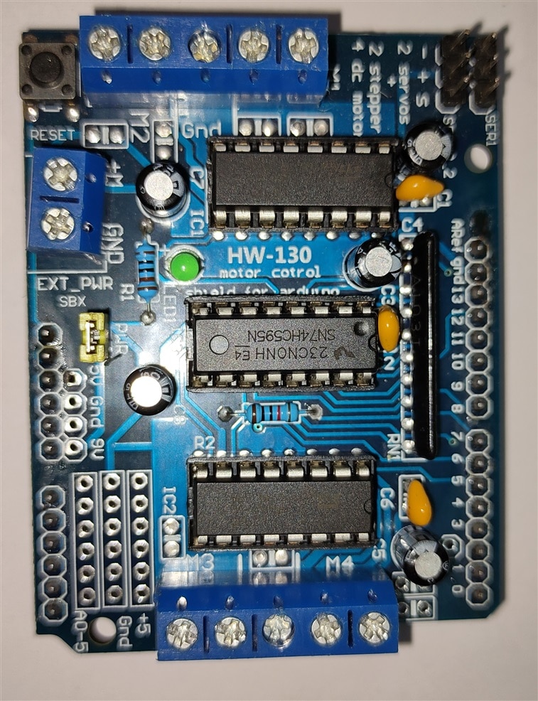
I was planning to use this shield with the Uno Q SBC for a 4 wheel drive. However, I wasn't sure whether it could damage the board before I had fully reviewed it, so I decided to postpone testing the shield. I'll update this with a link to the project once I've completed it.
| {gallery}My Gallery Title |
|---|
|
|
|
|
|
|
 |
The Arduino UNO Q is not simply another Arduino board, nor is it merely another Linux single-board computer. Instead, it represents a hybrid architecture that combines a high-performance microprocessor and a real-time microcontroller within a single platform. For years, developers and hobbyists have built similar systems by combining separate microprocessor-based SBCs with external microcontroller boards. The UNO Q integrates both approaches into a single device, with the microprocessor handling computationally intensive workloads such as Linux applications, networking, AI inference, and multimedia processing, while the microcontroller manages precise, deterministic, and real-time hardware control tasks.
While the software ecosystem is still evolving and certain areas of the documentation could be improved, the UNO Q offers a compelling platform for developers seeking the flexibility of Linux alongside direct hardware access and real-time control. By bringing together capabilities that traditionally required multiple boards and complex integration, the UNO Q simplifies development while retaining the strengths of both computing worlds in a single compact unit. From the Linux side, the board demonstrated respectable performance throughout benchmarking. CPU performance scaled well across all four Cortex-A53 cores, storage throughput was more than sufficient for typical SBC workloads, and cryptographic performance was strong enough for secure networking and IoT applications. During extended stress testing, the board remained stable under sustained CPU and GPU load, suggesting that it is capable of handling continuous workloads rather than only short benchmark runs.
However, Linux performance alone is not what makes the UNO Q interesting. Many SBCs can offer similar or even higher benchmark numbers. The real distinguishing feature is the integration of the STM32U585 microcontroller alongside the Linux processor and the communication bridge that connects them. The board's 14-bit ADC and 12-bit DAC are particularly valuable additions. Potentiometer and LDR testing demonstrated the increased analog resolution compared to traditional Arduino boards, while DAC loopback testing confirmed the functionality of the onboard analog output hardware. For users coming from platforms such as Raspberry Pi, having high-resolution analog capabilities available without additional hardware is a significant advantage. Peripheral compatibility was generally good. I²C communication was verified using an OLED display, PWM generation was tested using a servo motor, and standard GPIO functionality operated as expected. While a few libraries required platform-specific alternatives due to the Zephyr-based architecture, suitable replacements were available and functioned correctly once identified. One of the most useful discoveries during testing was the flexibility provided by App Lab and the RPC bridge. Traditionally, a project requiring Linux processing and real-time hardware control would involve at least two separate boards communicating through serial links or custom protocols. The UNO Q eliminates much of that complexity. The Linux processor can focus on networking, user interfaces, AI inference, or data processing while the STM32 handles sensor acquisition and timing-sensitive operations. App Lab further simplifies this arrangement by managing deployment and communication between both processors, allowing developers to concentrate on application development rather than infrastructure.
The board also serves as an accessible introduction to STM32 development. Many hobbyists are aware of STM32 microcontrollers but are often discouraged by the complexity of HAL libraries, low-level peripheral configuration, and vendor-specific tooling. By supporting the familiar Arduino development workflow, the UNO Q lowers the barrier to entry while still exposing users to industrial-grade STM32 hardware.
The hardware itself also presents several thoughtful design decisions. Support for both USB-C and 7–24V DC power input increases deployment flexibility, while the apparent use of multiple power rails and protection circuitry suggests that considerable attention has been given to power management. The ability to access the board remotely over the network proved especially convenient during development, reducing cable clutter and making the board feel more like a miniature server than a traditional development board. Ultimately, the Arduino UNO Q should not be viewed solely as an Arduino board, nor solely as an SBC. It occupies a space somewhere between the two. Users looking only for maximum Linux performance may find faster SBCs elsewhere, while users interested only in simple microcontroller projects can find cheaper alternatives. The UNO Q becomes most compelling when a project requires both worlds simultaneously.
For robotics, industrial monitoring, IoT gateways, data acquisition systems, edge AI applications, sensor-rich projects, educational environments, and rapid prototyping, the combination of Linux computing and STM32 real-time control on a single board is extremely powerful. Rather than replacing existing platforms, the UNO Q brings together capabilities that would normally require multiple devices, making it one of the most interesting and versatile development boards currently available in the Arduino ecosystem. The UNO Q may still be a young platform, and its software ecosystem continues to evolve, but its underlying concept is strong. After evaluating both its SBC and microcontroller capabilities, it is clear that the board offers far more than benchmark numbers alone. Its greatest strength lies in how effectively it combines two traditionally separate development environments into a single cohesive platform, enabling developers to build complex connected systems with considerably less hardware and software overhead than would otherwise be required.
This was my first RoadTest, so I approached it by performing the standard benchmarks and evaluations that I found commonly used in other SBC reviews and RoadTests. Reading those reviews gave me an understanding of how such evaluations are typically conducted, but carrying out the tests myself proved to be an entirely different learning experience. Working directly with the hardware taught me far more than theory alone could have. From finding compatible backports of benchmarking utilities and understanding CPU governors and their operating modes to interpreting system logs and troubleshooting unexpected issues, every challenge helped me gain practical knowledge and hands-on experience. Throughout this review, I have tried to keep the content simple and easy to follow while covering the board's features and capabilities. I would like to sincerely thank the entire Element14 and Arduino teams for selecting me as a RoadTester and providing me with the opportunity to evaluate this excellent hybrid SBC platform. As this was my first RoadTest, I did extend the schedule slightly while learning the review process, but I made every effort to perform meaningful tests and present accurate observations.
I hope this review proves useful to anyone considering the Arduino UNO Q and meets the expectations of both the RoadTest program and the community. Thank you for taking the time to read it to the very end. I would greatly appreciate any feedback, suggestions, or comments, as they will help me improve my future reviews.