RoadTest: Apply to review the ams OSRAM AS1170 Evaluation Kit
Author: arvindsa
Creation date:
Evaluation Type: Connectors & Cable
Did you receive all parts the manufacturer stated would be included in the package?: False
What other parts do you consider comparable to this product?: LM3644/LM3643 (TI), AL3644 (Diodes Inc.), and MAX20360 (Maxim) — the TI parts are the most direct comparison, better documented but lower peak current; the MAX20360 competes at the high-current end but is a significantly more complex integration.
What were the biggest problems encountered?: Missing pull-up resistors that are never mentioned in documentation, ESP32 firmware that references hardware not present on the board, and a getting started guide with enough gaps that every problem required going outside the provided materials to solve.
Detailed Review:
High-current LED drivers are not rare. TI, Diodes Inc., and Maxim each offer dozens of parts that push current into an LED at a fixed ratio of some input reference. What makes the AS1170 interesting is its scale and its architecture.
The AS1170 is a single-chip inductive DC-DC boost converter paired with two independent constant-current sinks. Each sink delivers up to 1000 mA, giving you a combined 2000 mA of LED drive current from a 2.7–4.4 V supply. That is not LED driver territory in the conventional sense - it is VCSEL territory, camera flash territory, high-power illuminator territory. You are not running a status LED. You are running something that gets hot if you hold it on too long.
The architecture matters because most drivers at this current level are either dumb - a fixed sense resistor and a control pin - or require an entire evaluation ecosystem before you can get anything running. The AS1170 occupies an interesting middle ground: fully I2C-configurable, all parameters software-writable, yet small enough to disappear into a WL-CSP13 package under a board. The two current sinks (LED_OUT1 and LED_OUT2) can run independently, load-balanced, or cascaded. Current steps at 3.5 mA per LSB across an 8-bit register, giving you 0 to roughly 892 mA per channel in 256 steps. Clean.
The OSRAM AS1170 EVK Kit gives developers a way to evaluate the chip before committing to a BOM and to validate firmware against a known-good AS1170 circuit. This review approaches it from the perspective of an engineer choosing between LED drivers - someone who needs to get up and running quickly and with minimal friction. Evaluation is structured around four areas:
The kit ships with:
The pairing is intentional. The AS1170 EVK board exposes its I2C lines - SDA on E1, SCL on D1, STROBE on E2 - through the 8-pin header. The ESP32-S2 sits between USB and I2C: it receives commands from the PC, translates them into I2C register writes, and reports back. The PC software never communicates with the AS1170 directly; it talks to the ESP32.
The LED breakout boards are small, purpose-built daughterboards. Each mounts one OSRAM high-power LED and routes its anode and cathode to a connector that matches the EVK's LED_OUT1 and LED_OUT2 terminals. They spare you the work of hunting down appropriately rated LEDs and wiring your own test setup from scratch.
The hardware itself is physically solid. The EVK PCB is well laid out, components are clearly labelled, and the I2C address - 0x30 on this board, with A-SELECT pulled low - is called out in the documentation. The kit contained everything it was supposed to.
One evaluation that could not be completed was a thorough power profile of the daughter board - specifically, the current ramp behaviour, actual current draw under load, and thermal response over time. To do this properly, additional LEDs beyond what were supposed to be provided along side the kit would have been necessary. The two breakout boards cover basic functional bring-up, but characterising output behaviour across different load conditions requires a broader set of test devices. That data is absent from this review, and it is a genuine gap for anyone evaluating the AS1170 in a high-current illuminator or flash context where knowing the actual versus programmed current curve matters.
ams OSRAM provides a PC GUI application (AS1170-GUI, V1.1) with the kit. The idea is straightforward: plug in the ESP32 via USB, open the GUI, select the serial port, and get a complete graphical interface for configuring all AS1170 registers without writing a single line of code. No installation required - a genuinely useful thing to offer with an evaluation kit.
That promising start did not last. The host computer was missing drivers for the CP2102 USB-to-serial converter on the ESP32 board. Installing them was quick, but there is no clear guidance on this anywhere in the getting-started material. The answer eventually turned up not in the official guide but on a random documentation page, buried in an image.

The GUI launched and showed a connected MCU, then prompted navigation to the configuration screen - which is the only thing in that initial view. That intermediate step adds nothing; the application could simply open to configuration directly.

The configuration screen itself is functional but low-contrast and not particularly accessible to users with low vision. Those are fixable issues. The critical problem was not: the Chip ID never registered as detected. After trying reconnection, different cables, and a different computer, the result was the same. There is no troubleshooting guide to consult.
Digging into the firmware source in the same repository as the GUI (https://github.com/ams-OSRAM/AS1170-GUI/blob/main/ESP32/AS1170_i2c_v0.ino) revealed this:
// Define a function to load registers from a CSV file
int loadRegisters(String filename, Register regs[]) {
  File file = SD.open(filename);
  // ...
An SD card. A CSV file. Neither exists in the repository, and the EVK board has no SD card slot. That raised immediate doubts about whether the firmware shipped on the ESP32 was correct - or present at all.
Rather than debugging an unknown firmware state, a custom firmware and matching GUI were written from scratch, modelling the interface closely on the original. A basic I2C scanner at startup detected nothing. Checking pin assignments against the EVK schematic revealed that the board does not use the ESP32's default I2C pins - it uses GPIO 12 and 13. After updating the firmware accordingly, the scanner still detected nothing.
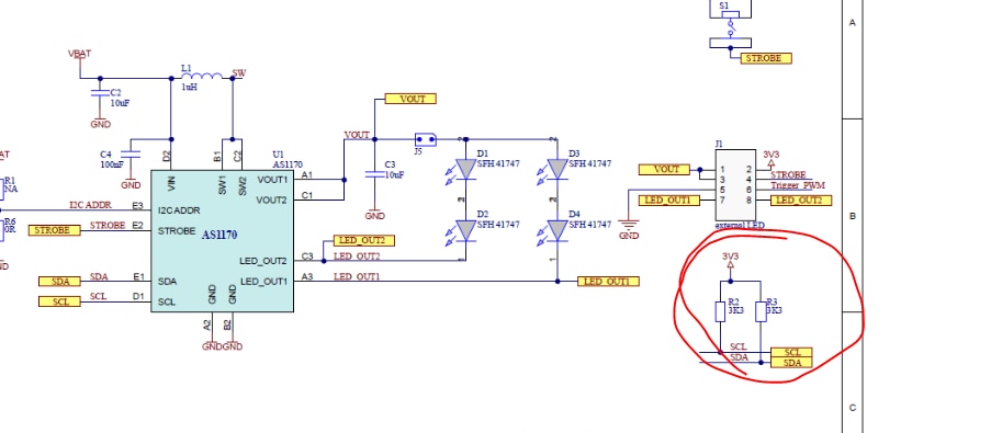
The root cause turned out to be hardware: pull-up resistors R2 and R3 were not populated on the board. Once soldered in, everything worked. Whether this was a board assembly defect or an undocumented user step, the documentation makes no mention of it either way.

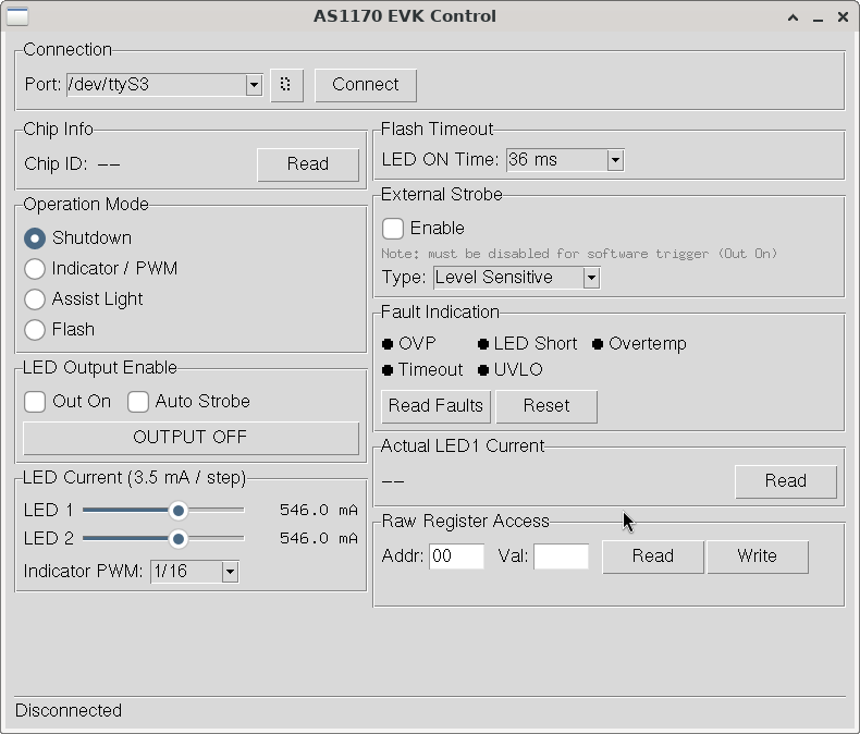
The vendor software is a starting point you will quickly outgrow. For any serious evaluation work, you will want firmware you control. The approach taken here was an Arduino driver for the AS1170 running on the ESP32-S2, exposed as a JSON serial bridge, with a Python/Tkinter GUI on top.
Once I2C communication was established, the AS1170 was tested across all documented operating modes and register functions. It is a well-designed part. What follows is a functional breakdown based on direct register-level testing.
The four modes - Shutdown, Indicator, Assist, and Flash - are selected via a 2-bit field in the Control register and behave exactly as documented.
Shutdown (0b00) cuts the boost converter cleanly. I2C continues to respond and registers retain their values. Current draw drops to the expected standby level. This is useful for applications that need the chip present on the bus but consuming nothing while idle.
Indicator mode (0b01) runs a 31.25 kHz PWM with the lower 6 bits of the current register active. The output is stable at low brightness settings and the frequency is high enough to eliminate visible flicker. This mode is well-suited for status indicators and always-on pilot lighting where continuous low current is acceptable.
Assist mode (0b10) opens 7 bits and sits between Indicator and Flash in both current range and intended use. It behaves predictably as a mid-power operating point - useful for applications that need more drive than an indicator but where full flash timing is not required.
Flash mode (0b11) is where the AS1170 is at its most interesting. Full 8-bit current, the boost converter running at full capacity, and a hardware timer that cuts the output automatically when the programmed timeout expires. The self-clearing of the mode bits and out_on bit on timeout expiry is behaviour worth paying close attention to in firmware: if your code polls the mode register after a flash, it will read back zero. This is correct operation, not a fault. Plan your state machine around it.
The 8-bit current register with 3.5 mA per LSB gives 256 steps from 0 to approximately 892 mA per channel. The resolution is practical - steps are small enough that the difference between adjacent values is not visible in most optical applications, and the range covers everything from low-power indicator use through full flash current. Both channels were tested independently and the matching between them was good.
The two channels can be driven simultaneously with independent current settings, which is useful for applications that need two LEDs at different intensities or are driving two different emitters from a single driver.
The flash timeout register (0x05) is not linear, and understanding its encoding matters in practice. Values below 0x7F map to (value + 1) ms. Values above 0x7F map to (value − 127) × 8 + 256 ms. The result is a two-segment scale covering 1 ms to roughly 1152 ms.
All values tested across the full register range behaved as the formula predicts. At short timeouts (single-digit milliseconds), the output cut cleanly with no observed overshoot. At the longer end of the range, the timer remained accurate. For strobe and illuminator applications, the covered range is more than adequate.
Register 0x81 implements a current boost of approximately 11% above the nominal full-scale value. Accessing it requires writing 0xA1 to the password register at 0x80 first, and that unlock is valid for exactly one subsequent I2C transaction.
The mechanism works as designed. Write the password, immediately write the boost bit, and the boost activates. Any other I2C transaction between the password write and the boost write locks the register again. This is not a security measure in any meaningful sense - it is a write-protection guard against accidentally enabling a mode that exceeds the nominal current specification. The behaviour is clean and predictable once you know the one-transaction rule.
The 11% increase was measurable in testing. For applications operating close to the thermal ceiling, this register should be used carefully and with appropriate attention to duty cycle limits.
The chip responded reliably to I2C at 0x30 throughout all testing. No missed ACKs, no register corruption across repeated writes, no unexpected state after mode transitions. The Chip ID confirmed correctly and matched the datasheet value. The register map is exactly what the documentation describes with no undocumented surprises encountered.
The AS1170 is a well-executed part. The register architecture is logical, the operating modes cover a genuinely useful range, and the flash timer hardware offload is a real convenience for time-critical applications where relying on software timing would introduce risk. The current boost guard mechanism is thoughtfully designed. The two independent channels are cleanly matched.
The only unanswered question - through no fault of the chip itself - is how it behaves under realistic high-current load with a proper characterisation of the output current ramp, actual versus programmed current at different supply voltages, and thermal behaviour under sustained duty cycles. That data requires load conditions and additional LED hardware that were not available for this evaluation. It is the one gap that remains before this part could be recommended without qualification for a production design in a high-current flash application.
For the use cases this part is designed for - camera flash, high-power IR illuminators, VCSEL drive - the register-level behaviour inspires confidence. The chip does what it says it does.
The getting started experience was genuinely difficult - and that matters more than it might seem. When you are evaluating multiple EVKs in parallel, your time per board is limited, and first impressions carry weight. A missing pull-up resistor, firmware that references an SD card that does not exist, driver installation steps buried in an unrelated documentation page, and a GUI that silently fails to detect the chip all stack up fast. Taken together, they do not read as minor oversights - they read as a kit that was not validated end-to-end before shipping. The honest risk is this: if I had been moving quickly across several competing parts, I would have put this board down and questioned whether the AS1170 itself was the problem. The chip is not the problem. But the EVK makes it very easy to think it is, and in a competitive evaluation that can be enough to lose a design win before the chip ever gets a fair test.
I am bit disappointed that my first RoadTest review had to be on the critical side. But I am giving my honest review of how it worked out for me. You can find the ESP32 Firmware and the GUI I made here: https://gitlab.com/arvindsa/as1170-evk-companion. Hopefully other Developers running into the problem might find the solution here.