RoadTest: TI Robotic Systems Learning Kit (TI-RSLK)
Author: fmilburn
Creation date:
Evaluation Type: Development Boards & Tools
Did you receive all parts the manufacturer stated would be included in the package?: True
What other parts do you consider comparable to this product?: The product comes with educational videos and supplemental material that goes into greater depth than other small robot kits that I am aware of. Most of the other kits use the Arduino IDE. Students using this kit will gain access to a modern ARM microcontroller (the MSP432), professional level Code Composer Studio IDE, and instruction on how to program it at the register level with full debugging.
What were the biggest problems encountered?: The training is derived from educational material written for undergraduate college level students. These students have access to a professor and / or lab instructors that an enthusiast at home might not have. Despite this, and despite being self taught for the most part, I was able to successfully complete all of the modules in the basic kit.
Detailed Review:
Introduction
The Texas Instruments – Robot Robotics System Learning Kit (TI-RSLK) was developed with Dr. Jon Valano at the University of Texas to give undergraduate students an understanding of how electronic systems work. The kit comes in a box with the hardware necessary to build the robot. The Code Composer Studio IDE for programming the microcontroller is available free on-line from Texas Instruments. The teaching videos, supplementary material such as lab descriptions, and code to get started with the modules is also available on-line. There are two versions of the kit – a basic and advanced model (with an upgrade from basic to advanced also available).
My proposal for the RoadTest was a write-up that targeted enthusiasts using the kit for self-education and others outside of a formal educational setting. The course finale is a competition with students using the kit to compete in different challenges. Lacking competition I chose to develop a Batmobile which could be used to fight crime in my home city of Seattle. Or at least entertain my grandchildren. Don’t miss the short documentary at the end of the RoadTest.

How to Read this RoadTest
The first sections describe how I scored the kit, who might benefit from it, and thoughts about the components. Following that is detail of the 20 learning modules. The modules are broken down into a table describing the associated videos, notes I took while watching the videos, and then detail about the labs for the module. Following that is a short summary of my takeaways from the module.
Note that I received the basic maze kit which does not contain all the components of the advanced kit. The modules that cover the components in the advanced kit will not be reviewed although I will offer some comments, especially where I think the learning experience would be improved by their inclusion.
At the end of the module write-up I noted the approximate time I had spent on the kit up to that point. It is approximate because I worked intermittently, didn’t track it precisely, and also tried to back out the time spent doing documentation for the RoadTest review.
After finishing the review I considered rewriting portions as I felt the criticism might be interpreted incorrectly and be too negative. The notes were taken as I took the course and represent what I felt at the time. And being who I am, they mostly reflect what I would do different. The assessment of an educational product by a single individual is by its very nature subjective. What might suit me might not be the best for others. The course covers a lot of material and there is no way for it to be all things to all people. Despite my criticisms (and in spite of my own shortcomings as a student) I finished all the modules, understand the material, and learned a lot. It is a good product.
Grading
Since this is an educational product, I am going to grade it on a basis similar to that used when I was a student and prior to grade inflation where everybody gets an A. To wit, 10 is exceptional, 9 is very good, 8 is good, 7 is passing, 6 is barely passing, 5 might have a chance if they cram for the final, and anything below that the student is in the wrong field of study.
Product Performed to Expectations (8): The MSP432 has lots of IO and works quite well on this robot. The reflectance sensor is picky about the background and the tape used for tracking. But is quite accurate under the right circumstances. Bumper switches don’t protrude that far and narrow objects will pass between them. The Pololu robot and motor driver are of good quality and performed well.
Specifications were sufficient to design with (9): The only design involved is with the firmware design. The MSP432 is more than adequate.
Demo Software was easy to use (8): What I will call the demo software was the sample firmware included in the downloaded code for Code Composer Studio and the code snippets shown in the videos. These were difficult to follow in places – would be easier in a traditional educational setting where questions could be asked.
Product was easy to use (8): This is going to depend on your familiarity with microcontrollers and basic electronics. Persons without the basics will really struggle I think, especially with the C code.
Support materials were available (9): There is a lot of hardware support material including TI training, forums, and documentation. Pololu documentation and support is good. I don’t know if there is direct support for the course material but getting the answer to specific software questions is available on various forums like Element14.
The price to performance ratio was good (8): This will depend on what you are after. If you are after the training which is the intended purpose it is good. If you are already knowledgeable about microcontrollers and want an all-terrain robot it won’t be good at all.
Unboxing
The kit came securely double boxed and arrived without damage. The inner box is in TI livery and large enough to store the robot after completion.

The contents of the basic kit include:
· SimpleLink™ MSP432P401R MCU LaunchPad Development Kit
· Romi Red chassis kit with motors and wheels
· Motor driver and power distribution board includes TI DRV8838 motor driver
· QTR-8A Reflectance sensor array with 8 IR LED/phototransistor
used as a proximity or reflectance sensor
· 6 Bump switches for obstacle detection
· Rechargeable batteries
· Wires, cables, passives and all mechanical components to build the robot
Note that while the kit comes with rechargeable Ni-MH batteries it does not include a battery charger (which I already had). For the most part everything else is there although I did substitute my own parts in a few cases because sometimes I am fussy and thought the build would be better :-). As well, as will be noted later, I feel the basic kit should come with the Pololu encoders which are include in the advanced kit.
All of the components meet the requirements set out in the learning modules for the intended undergraduate course(s). I will give further thoughts on their use in the detailed discussion of the modules.
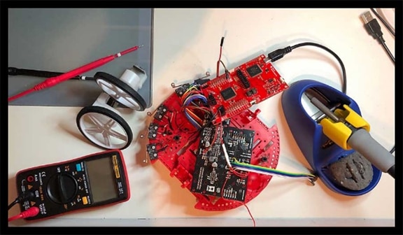
A multimeter and access to an oscilloscope are beneficial while taking the course. In some cases a logic analyzer will suffice. The course software includes the TExaS software oscilloscope and logic analyzer but they are quite limited. A soldering iron is necessary for soldering through hole components.
Who is the kit for?
As stated above, the basis for the kit is coursework developed for undergraduate students and the kit was put together to fit their needs. I suspect it fits well in well the University of Texas curriculum where pre-requisites and course objectives to meet future needs is well defined. How well it fits the needs of enthusiasts and others outside a formal class depends on where they are in the learning process and what their objectives are.
Here I will point out that the course is primarily about firmware development for the MSP432 in C. There is discussion of basic electronics but it is light. There is even less coverage of the mechanical aspects. Designing and building a robot from scratch is not a course objective.
Those who are proficient in embedded programming in C for microcontrollers, especially those familiar with TI ARM microcontrollers may not gain much from the course. The hardware itself may be of interest however.
Those with no knowledge of embedded programing in C for microcontrollers will almost certainly struggle and I recommend they at least take a course in basic C and becoming familiar with programming registers before attempting the course. Take the time to go through some of the TI training on the MSP432 and Code Composer Studio.
I am a self-taught electronics enthusiast and the kit fit my needs well. I have experience programming the Texas Instruments MSP430 line of microcontrollers but have limited knowledge of the MSP432. The course stretched me in some places and was old material in others. One of the primary benefits of the kit is the training associated with it and that is what sets it apart (along with quality of parts in some cases) from cheaper kits available elsewhere.
To be clear, this is not an Instructables type project with detailed build instructions and all the code the user needs to put it together. Nor is like some of the other robot kits available using the Arduino IDE with all of the libraries necessary to make it run. To complete the course it is necessary to dig deeper into the microcontroller and there is less hand holding – and that is a good thing for those looking for a greater level of understanding.
The kit would be most fun done in a group setting and I think it could be tailored for an advanced High School class led by someone who could help in the rough spots.
It took me approximately 54 hours to get through the training for the basic kit – not including this write-up. Some might get through faster, others slower. There are a number of suggested topics for additional study which I did not do and adding these would increase the time spent.
Among the topics I liked best and learned new things were the sections on:
· Debugging techniques
· The timing of tasks
· Bit banding
· Interrupt Vectors, numbers, names, and priority
I would have like to have seen the course make use of TI-RTOS or FreeRTOS.
Important: The modules consist of supplementary documents and the videos which contain lecture and lab videos. It is useful to go through the supplementary documents first. Sometimes the most important information is in the documents and the videos do not cover all information.
High Level Observations and Criticisms
In some case the modules would benefit by being broken into a greater number of smaller modules with simpler labs.
There is essentially no discussion of the mechanical considerations and issues in building a robot.
I stumbled around the organization of the code for a while. This would have been simpler with a lab assistant or the professor to explain the organization.
The effort put to such topics as assembly language are done at the expense of coding in C, electronics, and the mechanical aspects of robotic systems.
The course does not teach how to set up and start a project in CCS. The student gets no idea about watchdog timers and turning them off, the header files that come with the MSP432 in CCS, optimization levels, etc. Go to the TI training for this.
Encoders are necessary to get the robot to travel in a straight line and to make accurate turns and that is made clear in the lectures. After making my first simple robot without encoders I decided not to make another that did not have them. Accordingly, I ordered the encoders from Pololu as soon as I realized my kit did not come with them. They are approximately $9 with $4 additional for shipping in the US. I suggest that if a Rev. 2 of the kit is made they include these even if they have to bump the price.
Volume level in the videos isn’t that good in places, especially some labs, but is mostly acceptable. Closed caption is not always aligned with the spoken word.
The lessons do not address where information is in the datasheet or family user guide. This is important information that newcomers may not appreciate and is an important skill to pick up early. At least some introduction to the datasheets is appropriate.
What follows is a module by module overview of the training material with observations on the hardware where it is introduced in the module. Feel free to skip through, concentrating on the summary thoughts where a module looks interesting.
0. Getting Started / Introduction
A number of helpful links are provided in the introduction and are repeated at the bottom of this RoadTest review.
1. TI-RSLK Module 1 - Running Code on the LaunchPad using CCS
No. | Type | Time | Description |
1.1 | Lecture | 11:04 | Introduction to embedded systems |
1.2 | Lab 1.1 | 04:28 | Set up CCS and import the learning kit software |
1.3 | Lab 1.2 | 02:14 | Compiling and running example |
1.4 | Lab 1.3 | 03:26 | TExaS logic analyzer |
1.5 | Lab 1.4 | 03:13 | TExaS oscilloscope |
The first lecture is a broad overview of embedded systems. It would be of value to those just getting started with embedded systems but of limited value to electronics enthusiasts with some microcontroller background.
The labs assume that Code Composer Studio (CCS) is already installed. There is very little discussion of actually using CCS and I suggest that those who are new to it get an overview through the Texas Instruments training (links are at the bottom of the RoadTest). TI-RTOS and EnergyTrace are not discussed in the lecture.
Lab 1.1 is important as it describes how to download and access the course software that will be used.
Lab 1.2 is a very brief introduction to CCS. I would have expected some discussion of what the compiler, assembler, and linker do are as well as what happens when the microcontroller is flashed.
Lab 1.3 is a very short description of how to compile and run a simple program. There is no discussion of how the code works.
Lab 1.4 is a quick introduction to the TExaS logic analyzer which runs on the PC. Professor Valvano recommends using an actual logic analyzer if you have one. I see how TExaS might be of use to someone who does not have logic analyzer but it is very rudimentary and would also cause some overhead within your program. I plan to use my own dedicated logic analyzer if necessary.
Lab 1.5 is a quick introduction to the TExaS oscilloscope. The same comments apply as to the logic analyzer. I have an oscilloscope which I will use when necessary.
Summary Thoughts: The first module skims through the material quickly. Students new to CCS should get familiar with the TI material first. The Texas logic analyzer and oscilloscope do not qualify as lab instruments but may be useful for those who don’t have access to such equipment. I spent about an hour on this module but expect much longer if you don’t have CCS and the drivers installed.
Total hours to date: 1 hour
2. TI-RSLK Module 2 – Voltage, Current, and Power
No. | Type | Time | Description |
2.1 | Lecture | 26:17 | Introduction to voltage, current, and power |
2.2 | Lab 1.1 | 03:30 | Measuring reactance of a capacitor |
2.3 | Lab 1.2 | 02:42 | Measure LED (I,V) response curve |
The lecture is a very basic introduction to voltage, current, and power. The objective is to give some understanding of Ohm’s Law and what voltage, current, and power are. High school students with some physics will have covered the material in more detail than the lecture and college students who have had a first course in physics or an introductory course in electrical engineering will have studied it in much greater detail. It might serve as an introduction or refresher of very basic concepts for some.
Lab 2.2 uses the LaunchPad to create a square wave at different frequencies while connected to a RC circuit on the breadboard. The code is not explained but it uses a simple delay to toggle a pin and create the square wave. An oscilloscope (or TExaS) can be used to the measure the voltage across the capacitor which is in series with the resistor at different frequencies and from this the reactance calculated. The highest frequency generated was 1000 Hz – quite low.
The introduction warns that the measured and predicted values may differ (but does not explain what the causes might be) and this was certainly the case. It does however illustrate how a capacitor can be used as a filter. I don’t remember it discussing cutoff frequency which is in the quiz.
Lab 2.3 uses the LaunchPad as a 3V3 power source to light a LED in series with a resistor. The resistor value is varied and the voltage across the LED is measured and the information used to generate a V-I curve.

Summary Thoughts: This is a rudimentary introduction to basic electronics and can be skipped by most electronics enthusiasts. I am not sure that the TExaS tools will be that useful (but stand to be proven corrected) and recommend at least having a digital multimeter. I spent about an hour and a half on this module. I recognize time is limited but an introduction to issues beginners face such as component selection is missing.
Total hours to date: 2.5 hours
3. TI-RSLK Module 3 – ARM Cortex M
No. | Type | Time | Description |
3.1 | Lecture | 20:09 | Cortex M architecture and introduction to instruction set |
3.2 | Lecture | 23:01 | More assembly instructions, the stack, and basic program control |
3.3 | Lab 3.1 | 03:09 | Debugging |
The first lecture is an introduction to processor architecture and discusses RISC and CISC, Harvard and Van Neumann architecture. Memory is outlined and an overview of the registers is given. A handful of instructions are discussed. Race conditions are hinted at. Addresses modes and data are quickly overviewed. This is one of my weakest areas of knowledge, but I did not learn much from the lecture.
The second lecture is about assembly language programming. I don’t believe the level of detail covered is sufficient to help a person with no prior knowledge debug code as is stated early in the lecture. It covers AND, OR, XOR, <<, >>, signed and unsigned numbers, etc. Overflow is discussed. The stack is discussed and how it is accessed. Basic subroutines and control are presented (in assembly).
Lab 3.1 covers a handful of debugging techniques that can be used in CCS but it is with assembly. Since this is an introductory course it could have been left to be covered in the C / C++ section and omitted here in my opinion.
Summary Thoughts: I think time should have been spent on an overview of the architecture and memory as it is presented in the MSP432 datasheet. The second lecture would have met most audience needs better by leaving most of the topics to the discussion of C / C++ and not covering assembly. The time saved could have been better spent on electronics. I spent about an hour on this module.
Total hours to date: 3.5 hours
4. TI-RSLK Module 4 – Software Design using MSP432
No. | Type | Time | Description |
4.1 | Lecture | 19:51 | Modules, program structure, and threads |
4.2 | Lecture | 26:31 | Introduction to C programming |
4.3 | Lecture | 17:27 | Debugging on the MSP432 |
4.4 | Lab 4.1 | 03:57 | Coding IR distance, breakpoints and functional debugging |
4.5 | Lab 4.2 | 4:08 | Coding maze scenarios, functional debugging w/ corner cases |
The first lecture covers programming on the MSP432 and discusses modules, program structure and threads. The discussion is predominately about breaking a problem into smaller and easier to code pieces. Covers headers and code files at a high level. There is brief coverage of doxygen.
The second lecture starts to discuss C programming. Covers bit operations, logical operations, conditional statements, loops, etc. The introduction covers things quickly and at a high level. It would be insufficient for someone who has not programmed before. Covers local and global scope in a clear way. Covers signed / unsigned variables and precision. Covers port registers. Covers constants and enumerated types. Touches on interrupts.
The third lecture covers “functional debugging” which tests one function at a time. It simulates an IR sensor and not an actual sensor. The method uses known inputs and known expected outputs.
Lab 4.1 uses only the MSP432 and teaches breakpoints. The idea is to develop a function that returns the distance given the raw input from an IR distance sensor. Why not use the datasheet from an actual IR sensor and show how to read it? The equation to be used for converting to distance is inside the Lab portion of the curriculum documents.
Lab 4.2 is an interesting problem where all of the possible error, danger, and operating scenarios of the robot in a maze are determined by the student. The video describes a way to stop execution after a fixed number of loops which I was not familiar with and may prove useful in future. The corner cases are tested by code provided by the course. I had to read the instructions a couple of times to understand and then lay out the code. I then managed to make a couple of errors which needed to be fixed. I am not entirely happy with the way I wrote my code and would be interested in seeing how a better programmer would have written it.
Summary Thoughts: This was the longest module so far and I spent 3+ hours on it. The coverage of code was light and done so quickly that it would be difficult for someone not already familiar with the C language, or at least proficient in another language to grasp it. Lab 4.1 missed an opportunity to demonstrate use of a datasheet. Lab 4.2 was well done in my opinion and demonstrated how to use functional debugging and about half the time was spent on this lab.
Total hours to date: 6.5 hours
5. TI-RSLK Module 5 – Battery and Voltage Regulation
| Type | Time | Description |
5.1 | Lecture | 21:32 | Discusses power sources, voltage regulation and monitoring power sources |
5.2 | Lab 5.1 | 02:04 | Measuring voltage and current from batteries |
5.3 | Lab 5.2 | 03:54 | Connecting Motor Driver and Power |
The lecture discusses sources of power (e.g. wall power with AC to DC converter, DC power such as USB, Batteries, etc. It also covers voltage regulation including switchers and linear regulators. There is a brief discussion of power budget and microcontroller sleep mode. Different types of batteries and their attributes are discussed. The kit uses six 1.2V NiMH rechargeable batteries in series (7.2V) rated at 1.8 Ah which gives roughly 3.6 hours runtime for the robot. The robot has a linear regulator to run the microcontroller and runs the motors directly off of the batteries. There is mention of the TI WEBENCH Power Designer and an overview of designing your own power supply. Measurement of power efficiency is covered.
Lab 5.1 Four batteries are connected in series and then run down through a 10 ohm resistor while measuring current and voltage. I’ve done similar experiments before and did not carry the project through to a drained battery. I did set up the lab and run it briefly as shown in the photo below.
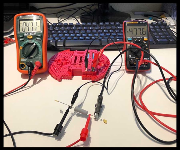
The experiment requires you to have a multimeter for measuring voltage and another for current. Batteries are provided but a charger is not. This did not seem like that useful a lab.
Lab 5.2 describes how to connect up power distribution and the mechanical assembly. Professor Valvano (or one of his lab assistants) should demonstrate how to cut the traces and do the necessary soldering in the video. I cut the traces with the razor edge of a box cutter and then tested with a multimeter to make sure there was no continuity. Here it is all wired up and ready for mechanical assembly.

The description of mechanical assembly could be improved but was not overly difficult. In addition I believe my kit substituted metal screws for plastic as the packet is labelled “.5in 4-40 plastic mach. Screws” but it contains metal screws. The instructions state “Align the standoffs with the four holes on the LaunchPad. Depending on where you choose to mount the LaunchPad, you may have to increase the side of the hole on the chassis to ¼ inch to accept the 4-40 screw”. I saw no possible way to align the LaunchPad with the chassis and not have to enlarge a hole. In the end I substituted some of my own hardware as I felt it made for a nicer assembly. Holes must be drilled in the breadboard so that it can be attached.
Following assembly I powered it up and checked 3V3 and 5V. I also checked to make sure there were no shorts across the breadboard since it had been drilled.

Summary Thoughts: The lecture gives good coverage of the material. See the Pololu site for information on correctly installing the battery compartment, motor driver, and mechanical assembly. Note that a battery charger is not supplied with the kit and running down your batteries before you get one in Lab 5.1 might not be a good idea. The material on cutting the traces, soldering, and assembly could be improved.
I spent about 4 hours on this module. The additional time was mostly because I was not pleased with the mechanical assembly and redid it. I also installing encoders which are not part of the base kit.
Total hours to date: 10.5 hours
Module 6 Prep: Assembling the Robot
At this point I decided to go ahead and assemble much of what remained of the robot body even though the video and course materials did not explicitly say to do so. I decided earlier in the week that I wanted to add encoders and have just received them so I soldered them to the motors first using the Pololu instructions. The male pins on the encoders insert neatly into the motor control board.
Next I soldered female DuPont connectors to the reflectance sensor array. There were not any screws in the kit that fit the holes in the reflectance PCB so I bought some #2 machine screws and nuts at the local hardware store. Metric M2 would work as well.
Surprisingly (to me anyway) the holes in the reflectance array do not line up with the holes on the bed of the robot. I could not stand the thought of nonsymmetrical parts that weren’t square so I used a Dremel tool to lengthen a couple of the slots. I placed the array further forward than the photos in the course materials show so that it could hopefully sense edges and not fall off a table. I chose to solder to the line sensor and use duPont connectors on the MSP432.
Here is the view looking at the top after inserting the motors.

This is a view of the bottom.

Summary Thoughts: Assembling the robot, including soldering, took about 3 hours because I kept fooling around with it trying to decide how I wanted to mount the reflectance array and then had to make a trip to the hardware store. Another thing, this robot needs more cowbell LEDs.
Total hours to date: 13.5 hours
6. TI-RSLK Module 6 - GPIO
No. | Type | Time | Description |
6.1 | Lecture | 22:13 | MSP432 GPIO |
6.2 | Lecture | 22:19 | GPIO Programming |
6.3 | Lab 6.1 | 03:02 | Interface reflectance sensors |
6.4 | Lab 6.2 | 02:45 | Test performance of sensors |
The first lecture covers I/O with a focus on GPIO. Of the 100 pins on the MSP432P401, 84 are IO. Describes pins and how they are arranged in ports. Outlines the various parts and their purposes on the LaunchPad. Discusses how the MOSFETs on the pins work and what constitutes high and low (VIL and VIH). Notes that the MSP432 is not 5V tolerant. Notes that current is limited to 6 mA (20 mA some pins).
The second lecture covers programming GPIO. Covers the following:
· Reading input – PxIN
· Writing output – PxOUT
· Selecting GPIO – PxSEL0 and PxSEL1
· Setting direction – PxDIR
Covers negative logic Vs positive logic where a low turns something on. Covers the QTR-8RC optical sensor used in the robot. This sensor requires a pin to be set both as an input and output.
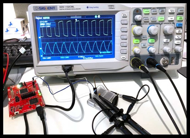
Lab 6.1 demonstrates how the QTR-8RC sensor works. The basic principle is that a 10 us output pulse is used to charge a capacitor on the QTR-8RC. Reflected IR light then causes a light sensitive transistor to discharge the capacitor. More light from a light surface causes a faster discharge and by measuring after a fixed period it can be known whether the surface is black or white since the GPIO pin on the MSP432 goes low when it meets the threshold for a low signal.
The following photo demonstrates the experimental apparatus and the quick discharge that occurs when the sensor is receiving reflections from the white table. The lower (blue) trace on the oscilloscope is the analog discharge from the capacitor. The upper (yellow) trace is the digital signal interpreted by the GPIO pin on the MSP432.

In this screenshot from the oscilloscope it can be seen that the time for the GPIO pin to read low is approximately 1.5 ms. This occurs when the capacitor discharges below approximately 1.7 V.
In the photo below the robot has been moved to the right so that the IR sensor is directly above the black tape. Note the longer period that the digital signal remains high. In fact, it doesn’t go low during the period shown because the capacitor doesn’t discharge that far with my setup.
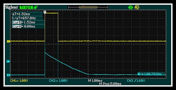
In the photo below the robot has been moved to the right so that the IR sensor is directly above the black tape. Note the longer period that the digital signal remains high. In fact, it doesn’t go low during the period shown because the capacitor doesn’t discharge that far with my setup.

Lab 6.2 takes the information learned in Lab 6.1 and uses it to determine how far the robot has strayed from the black line. The software is written by the student who then measures the reported deviation from center of the black line as the robot is moved. The photo below shows the setup.

I was surprised at how linear the data was although it is not particularly granular and the data plotted below is as fine as the resolution gets. It should be quite acceptable though for guiding the robot along a line.

Summary Thoughts: I recommend making reference to the datasheet and family reference manual in this module. I lost time trying to figure out exactly what was required by the labs and how the downloaded CCS files worked. This would not be as much of a problem in a group setting or with a lab assistant but may be an issue for those working through the course alone. After saying all that, this was a very educational and satisfying module. I spent about an hour on the lectures and around 3 hours on the first lab. The second lab was about 1.5 hours.
Total hours to date: 19 hours
7. TI-RSLK Module 7 – Finite State Machines
No. | Type | Time | Description |
7.1 | Lecture | 20:43 | Finite State Machine (FSM) theory |
7.2 | Lecture | 25:38 | Applying FSM as a central controller to the robot |
7.2 | Lab 7.1 | 02:35 | Designing a FSM |
7.3 | Lab 7.2 | 02:52 | Refining the FSM for line following |
The first lecture defines FSMs in a general manner and as an abstraction. It states that FSMs are “very simple” (ha ha). Sometimes they are. Here is a nice diagram from the lecture:

The video goes over an example using automobile traffic lights. Goes over both State Transition Graphs and State Transition Tables. It then uses structs and pointers to set up a FSM engine. Briefly touches on Mealy and Moore FSMs. Goes over all of this a bit quick.
The second lecture focuses on the robot and line following. He slows down a bit here and describes it in more detail but I got lost in places and had to go back and listen again.
Lab 7.1 has an intentional bug which the student has to fix by “adding more states”. They put a bug in the state machine which was easily fixed and I added LostLeft, LostRight, and Stop states. The lab took about an hour as I played around with it a bit.
Lab 7.2 I saw the problem to this lab while in Lab 7.1 and fixed it before I saw this video.
Summary Thoughts: This module is fairly easy if you are familiar with state machines and particularly if you are familiar with the approach Dr. Valvano uses (which I had seen before). I would be interested in how a person with knowledge of using FSMs in an industrial setting views these methods. I know one experienced programmer who thinks it overly restrictive. I spent about an hour on this module and about an hour and half on the labs.
Total hours to date: 21.5 hours
8. TI-RSLK Module 8 – Interfacing IO – Switches and LEDs
No. | Type | Time | Description |
8.1 | Lecture | 11:27 | Switches |
8.2 | Lecture | 18:57 | LEDs |
8.3 | Lab 8.8.3 | 02:38 | Interfacing Switches and LEDs |
The first lecture covers how switches work and how they are connected to the microcontroller. In particular, it prepares the student for installing bumper switches on the robot. Discusses “positive logic” where the switch gives 3V3 when pressed and “negative logic” where the switch gives 0V when pressed using pull down and pull up resistors. Covers the switches on the LaunchPad.
The second lecture covers in LEDs in some detail. The lab goes over using switches to control LEDs and starts with a discussion of how they work. Covers how to size a resistor to limit current flow to the LED. There is a discussion of controlling higher current but rather than a transistor it describes using an open collector NOT gate. Kind of strange. Notes that P2.0, P2.1, P2.2, and P2.3 can handle up to 20 mA. Covers LaunchPad – note that P2.0, P2.1, and P2.2 are high current LEDs. Shows how LEDs can be used to debug or convey information to the user.
The lab video was very difficult to hear. The exercise itself was quite basic with the goal of arming or disarming an “alarm” that would behave in different ways if “windows” are open or closed. The windows are simulated with buttons and the alarm signal with a LED. The photo below shows the alarm being armed.
I spent 45 minutes on the lab but would have been finished in less than 30 except for a bug that took a while to find. Checked the software and couldn’t find anything. Checked the circuit and found I had bent the leg of one of the switches and it wasn’t seated properly in the breadboard. Doh!
Summary Thoughts: This was a straight forward module with basic digital IO. It took me about 1.5 hours.
Total hours to date: 23 hours
9. TI-RSLK Module 9 – SysTick Timer
No. | Type | Time | Description |
9.1 | Lecture | 12:55 | SysTick timer fundamentals |
9.2 | Lecture | 11:35 | PWM and duty cycle |
9.3 | Lab 9.1 | 02:15 | Heartbeat |
9.4 | Lab 9.2 | 03:27 | Running sine wave output to adjust power |
The first video gives an overview of the 24-bit SysTick timer. The first task is to create delays, but later SysTick will use for interrupts. When the MSP432 is running at 48 MHz and the SysTick Timer is running at bus speed then 1 cycle is 20.83 ns. The largest possible range is 349 ms at which time it rolls over.
The second lecture discusses PWM and how to create it with the SysTick timer. Describes the time constant which is 63% of the time to turn on. For example a LED has a time constant to turn on of 90 ns vs. a motor of 100 ms. Describes duty cycle. Explains how the eye responds to the duty cycle of a rapidly changing LED as a change in brightness (power). Shows how to make a simple DAC with a low pass RC circuit
The Lab 9.1 video is difficult to hear and I found the directions hard to follow in places. It uses the SysTick timer to create PWM to a LED and then varies the duty cycle up and down. Switch S1 on the LaunchPad is used to turn it on and S2 is used to turn it off. The increase and decrease in PWM duty can be seen in the following video of my working code.
The lab took about 1.5 hours.
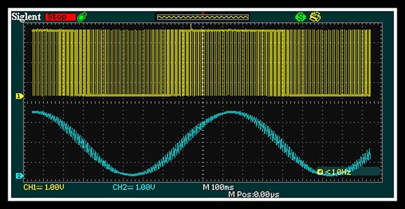
Lab 9.2 modifies the PWM output so that the duty cycle approximates that of a sine wave through the use of a table. It then adds a RC circuit to smooth the output so that it is closer to the average of the pulses. The oscilloscope shows a sinusoidal curve after the RC circuit which models the way the motor will react to PWM (i.e. it doesn’t stop and start with each pulse if the pulses are fast enough). The screen capture below from the oscilloscope shows the PWM output on the yellow trace and the smoothed output on the blue trace. Note that there is still a fairly wide band in the output even after smoothing.
Summary Thoughts: The lecture is straight forward but lab 9.1 confused me at first and it took a bit longer than it should have – again wouldn’t have been a problem if there was a lab assistant to answer questions. In all I spent about 2.5 hours on this module.
Total hours to date: 25.5 hours
10. TI-RSLK Module 10 Prep – Adding Bumper Switches to the Robot
The next mechanical work was to install the bumper switches. This took about 1.5 hours but I fiddled with it quite a bit as the parts were difficult to place by clumsy me. I was also interrupted about half way through to help save the neighbor’s dog who had fallen down the steep bluff behind our house and could not get back up. I did not count time saving the dog in the time to add switches to the robot.

Total hours to date: 27.0 hours
10. TI-RSLK Module 10 – Debugging Real-Time Systems
No. | Type | Time | Description |
10.1 | Lecture | 20:24 | Theory |
10.2 | Lecture | 20:00 | Interrupts |
10.3 | Lecture | 20:37 | SysTck Interrupt |
10.4 | Lab 10.1 | 03:17 | Running line sensor / black box recorder |
The first lecture covers the theory of debugging. Defines intrusiveness as a measure of how the debugging affects the parameter being measured. Describes using SysTick to determine how long it takes and dividing that by the time between calls to give a measure of intrusiveness. Discusses filters to reduce data stored. Performance debugging looks at where, when, and how long a section of code takes to execute. For example, could toggle a pin to allow timing how long the code takes to execute. Described bit-banding in a way I did not fully understand and had to read up on. Described in some detail how flash works and in less detail how to use it.
The second video covers interrupts. Interrupts will be used for bump sensors, motor overload, software traps, etc. Triggers for the ISR include: hardware needing service, new input data, output idle, periodic interrupt. Describes the foreground as the main loop and ISRs as the background. The robot will use shared global variables to pass data between ISRs and the foreground (in the form of a flag and mail).
The third video overviews periodic timing interrupts with SysTick. SysTick counts down from the contents of the value register and triggers an interrupt on the transition from 1 to 0 (modulo n-1 counter). When the microcontroller is running at 48 MHz the decrement occurs every 20.833 ns. Explains critical sections where shared globals or shared ports can be corrupted by interrupts in a read, modify, write. Gives example solutions such as removing shared globals / ports, bit-banding, giving equal interrupt priority so not interrupted, and disable / access / enable interrupts.
The Lab 10.1 video describes debugging with the IR sensors, but the lab write-up also uses the bump sensors. I found the lab write-up confusing and the video not helpful. It would have helped a lot to have a lab assistant or access to the professor. In the end I wrote my own code and did not directly follow the framework provided in the lab but got everything working. It took much longer than it should have because I just hacked it out and had to do a lot of debugging of my own hacks. Took approximately 8 hours. The following is a screen shot of the debug array for the bumper switches as seen in Code Composer Studio.

Note: Tried using blue painter’s tape and could not get a reading with IR reflection sensors.
Summary Thoughts: The module tried to cover too much and should be broken up. The lab and especially the code presented in the CCS files was hard to follow. I eventually found it easier to write the code based on my own framework and understanding of the objectives. TI training examples are typically easier to follow than was this module. The debugging techniques explored are powerful and useful.
Total hours to date: 36 hours
11. TI-RSLK Module 11 – Liquid Crystal Display
The Nokia display is not part of the TI-RSLK Maze Edition Basic but I happen to have one on hand as I have used them before in a number of projects. I may come back and do this module after completing the RoadTest. It is nice to have this training available as an option as the Nokia is an inexpensive addition to the kit.
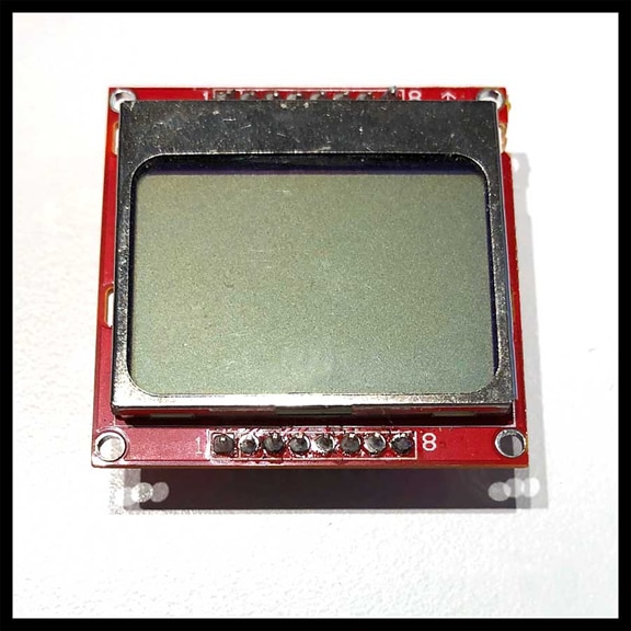
Note: This part is not part of the TI-RSLK Maze Edition Basic kit and was not part of the RoadTest.
12. TI-RSLK Module 12 – DC Motors
No. | Type | Time | Description |
12.1 | Lecture | 14:43 | Physics of motors |
12.2 | Lecture | 20:17 | Mechanical and electrical aspects of connecting motors |
12.3 | Lab 12.1 | 2:39 | Interfacing motors to the LaunchPad |
12.4 | Lab 12.2 | 1:46 | Testing how straight robot moves without encoders |
As Professor Valvano says, we finally made it (to the motors and making them move). The first lecture is not particularly advanced and the more technical parts of the slides are covered quickly without detail.
The second lecture covers the interface between the microcontroller and the motors. The motors require approximately 0.5 A. Duty cycle and PWM is used to control motor speed. Again, the technical aspects are presented in a simplified manner. Does not show or discuss datasheets. Shows how to use a TIP120 transistor which is not part of the kit. Discusses snubber diodes to take care of back EMF. Shows how to use a MOSFET as a driver with a BJT. Discusses H bridges. Discusses ICs with H bridges, e.g. the DRV8836 in the Pololu driver board. Discusses how to use the driver board to control speed with PWM, set direction with high or low logic, and disable the driver.
Labs 12.1 and 12.2 require that the robot be disassembled so that the controls from the microcontroller can be soldered to the motor driver and power distribution
board. Took a bit less than an hour to do that and test connections.
The main effort was to write and debug the motor drivers needed for both Labs 12.1 and 12.2. This took around 2 hours, much of it spent removing self-inflicted bugs and in one case an apparent bug that really wasn’t a bug. The motors were noisier than expected at first. It needs a proper switch instead of a jumper from the power module to the LaunchPad (used to disconnect the power module when programming through USB). Will probably need to change the pins used for motor control as they will interfere in a later module when a BoosterPack (e.g. Wi-Fi or BLE radio) is used. Measuring the current in Lab12.1 is difficult as are the other measurements since the motor control board is covered by the LaunchPad.
Lab 12.2 moves the robot in a preset pattern and demonstrates the inaccuracy involved when there is no feedback (encoders). This is the reason I ordered the encoders from Pololu as soon as I received the kit and realized they weren’t present. Also noted is that the bumper switches will not always activate on small obstructive surfaces – e.g. small round chair leg. Of course there are no bumper switches on the back so it can also back into obstacles. The robot is not as tail heavy and will do a “wheelie” if reversed at higher speeds. Assorted preparation, measurement and testing took this lab to a total of 4 hours.
The following video shows the robot in a pre-programmed test. It goes forward a fixed amount of time and hits a wall causing a bumper switch to activate and the motors to stop (a red LED turns on and indicates the braking). It then backs up a fixed amount of time, turns one way and then the other, and starts all over again.
Summary Thoughts: I have some concern about the power of the motors and their life but they are unproven concerns. The video technical discussion is simplified, especially the mechanical aspects. Pin choice looks to cause problems for future modules when BoosterPacks are needed. The need for encoders is on full display. This module took approximately 5 hours to complete.
Total hours to date: 41 hours
13. TI-RSLK Module 13 - Timers
| Type | Time | Description |
| Lecture | 14:28 | Timers and periodic interrupts |
| Lecture | 18:37 | Timers and PWM |
| Lab 13.1 | 01:58 | Timer generated PWM to spin motors |
| Lab 13.2 | 02:36 | Interrupt latency |
The first lecture starts with possible uses of a timer: measure frequency or period as an input, PWM as an output, and periodic internal interrupts. There are four 16 bit Timer A modules with four capture / compare registers on the MSP432. The coverage of the timer and how to use it was done quickly and I would have probably been lost without prior knowledge.
The second lecture covers PWM and using it with motors. A period is chosen that is shorter than the time constant of the motor and the duty is selected to give the power desired. The discussion on selection of parameters for NVIC was sparse and I will need to go back and review that at a later date. Covers setting the period with TA0CCR0 and duty cycle with TA0CCR1 and TA0CCR2 for the two motors.
I find the TI training explains how to use timer modules in a more easily understood way than this training. But finally we are using interrupts and timers instead of blocking code.
Lab 13.1 covers setting PWM for the motors with Timer A0. The lab code differs from the actual pins used in a confusing manner but is covered sufficiently to figure it out. I had this working and tested in about 2 hours.
Lab 13.2 uses Timer A1 to set an internal interrupt with a 100 Hz period to check the bumpers and turn off the motors if one or more bumper switches has been pushed. It took a bit more than an hour to finish this lab.
Summary Thoughts: The robot has essentially the same functionality as in Module 12 now but uses timer generated PWM and interrupts rather than blocking code and busy / wait. The lectures are rapid fire and do not reference the MSP432 Family guide. A review of the Family guide reveals that NVIC is covered in a very cursory manner and I will need to go back and revisit that. I spent about 4 hours on this module.
Total hours to date: 45 hours
Module 13 –Comparison to Previous Robot
At this point I have achieved in this course approximately what I functionally achieved with my previous robot. It was made mostly from toy parts, scrap wood, a MSP430F5529 LaunchPad, and a Pololu motor driver. I later added photoresistors and ultrasonic sensors. I built this robot when I first got interested in microcontrollers and the programming was done in Energia.

That was several years ago but I remember the build not taking so long and I attribute this to simplicity as well as design planning and knowing in advance what I wanted to do. As well, getting the motor driver to work with PWM is trivial in Energia. Although it did not hold up that well and I later disassembled it for parts I would emphasize to beginners that a robot with similar functionality to the kit can be built even if they are early on the learning curve. Quite a bit of learning can be achieved with lesser parts and equipment.
14. TI-RSLK Module 14 – Real-Time Systems
No. | Type | Time | Description |
14.1 | Lecture | 17:53 | Real-time systems theory |
14.2 | Lecture | 20:31 | Edge triggered interrupts on GPIO pins |
14.3 | Lab 14.1 | 1:34 | Real time response using bump switches |
The objective of this module is to make the bump interrupts respond quickly. The first lecture goes over periodic tasks, aperiodic or irregular (IO), and sporadic / unexpected (faults). Performance parameters include latency (time it takes to recognize an event has happened), response time, and priority. In a hard real time system the response time is guaranteed. In audio or vision streaming the real time system may not be so restrictive – e.g. packets are lost so there is some loss of quality. In a soft real time system the response time is less critical
The second lecture goes into detail on setting up an edge triggered interrupt on P1.4. Some of the material is a welcome repeat of information about interrupts previously covered.
The purpose of the lab is to interface the bump switches with edge triggered interrupts. A robot command language is developed. The oscilloscope or logic analyzer is used to determine how fast the robot takes to respond to a collision. Note: I previously connected the bump sensors to P8.3 through P8.7. But only Ports 1 through 6 can trigger interrupts. It is interesting that only one of the pins with interrupts (P6.3) is available on the header at the back of the MSP432 LaunchPad
In the following screenshot from the oscilloscope the switch triggers the interrupt and toggles a pin twice. It then clears the interrupt and toggles the pin once more. This is done in approximately 1.5 us.

Summary Thoughts: I sped through this module and did not play with it as much as I have some of the others since I am familiar with GPIO triggered interrupts. Total time spent was not quite 2 hours.
Total hours to date: 47 hours
15. TI-RSLK Module 15 – Data Acquisition Systems (IR Distance Sensor)
Infrared sensors are not part of the TI-RSLK Maze Edition Basic kit but I happen to have one as well as ultrasonic sensors.

Note: These parts are not part of the TI-RSLK Maze Edition Basic kit and were not part of the RoadTest.
16. TI-RSLK Module 16 – Tachometer (Encoder)
The Pololu encoders are not part of the TI-RSLK Maze Edition Basic kit but I ordered them after receiving the kit as I feel they are important addition to the kit They were installed as I assembled the robot so later disassembly and reassembly is not necessary.

They are approximately $9 with $4 additional for shipping in the US. I plan to come back and do this module after completing the RoadTest for the basic kit. As mentioned earlier, when discussing my first robot build, I feel encoders are a necessary addition to even basic robots.
17. TI-RSLK Module 17 – Control Systems
No. | Type | Time | Description |
17.1 | Lecture | 22:24 | Using inputs to set and control the robot |
17.2 | Lab 17.1 | 2:26 | Requires the encoders to maintain constant speed and go straight |
17.3 | Lab 17.2 | 2:41 | Requires the IR distance sensors to maintain a distance using proportional control. |
The first lecture covers how to use input on the robot to control it and accomplish a task. For example, the tachometer (encoder) can be used to set PWM and drive and adjust the motors to the correct speed. Covers control system at a high level without going into detail. Covers underdamped, critically damped, and overdamped responses to a change in set point. Describes the time constant for an entire system. Shows how motors differ and are nonlinear, especially the starting / holding friction. Will use the proportional and integral terms in the PID approach to drive the motor. This robot will not use derivative due to noise in sensors. Controller will be run at 10 ms intervals. Must run the controller slower than the sensors and faster than the motor. Will use integers instead of floating point. Gives some examples using P and I.
Lab 17.1 requires the encoders and since were not included in the basic kit I have not completed the lab at this point.
Lab 17.2 requires IR distance sensors and since they were not include in the basic kit I have not completed the lab at this point.
Summary Thoughts: This is one of the more important modules in the course as the methods discussed are at the heart of robotics. While I did not perform the lab experiments, I did immediately apply the material in this module to a self-inflicted competition challenge – turning the robot into the Batmobile and running it through downtown Seattle. I have some prior experience with PID and control systems. I spent about an hour on this module watching the videos and reviewing the lab material.
Total hours to date: 48 hours
18. TI-RSLK Module 18 – Serial Communication
No. | Type | Time | Description |
18.1 | Lecture | 8:42 | FIFO queues and buffered I/O |
18.2 | Lecture | 12:33 | Using UART on the MSP432 |
18.3 | Lab 18.1 | 4:52 | Interrupt driven UART driver |
18.4 | Lab 18.2 | 2:39 | Command Interpreter |
This module is only really needed if the Wi-Fi or Bluetooth radios are used. I thought the explanations of how UART works were good but there was no detail on how to implement it. Best to go to the TI training if you have trouble with the datasheet and / or family guides.
An easy to program FIFO is described in the first lecture.
The second lecture explains how the MSP432 UART works, but does not describe how to implement it in detail. Rather, it directs the student to the datasheet.
Lab 18.1 only requires the MSP432. The example UART code is fairly easy to follow and the FIFO easy to implement.
Lab 18.2 only requires the MSP432 and optionally a robot interpreter is demonstrated that can be used to direct the robot. I have implemented similar function in the past on the MSP430F5529 but thought the way it was suggested here was a clean way to do it.
Summary Thoughts: This is a useful module but only applicable to the robot if the Bluetooth or Wi-Fi modules are available. I spent about an 2 hours on this module.
Total hours to date: 50 hours
19. TI-RSLK Module 19 – Bluetooth Low Energy
The CC2650 BLE BoosterPack is not part of the TI-RSLK Maze Edition Basic but I happen to have one on hand. I plan to come back and complete this module after completing the RoadTest for the tested version and submit an update.

20. TI-RSLK Module 20 – Wi-Fi
The CC3200 Wi-Fi BoosterPack is not part of the TI-RSLK Maze Edition Basic but I happen to have an older CC3100 on hand that I have used in other projects. I may come back and complete this module after completing the RoadTest.

Note: This part was not part of the TI-RSLK Maze Edition Basic kit and was not part of the RoadTest.
21. My Challenge
Since I did not have anyone else to compete with I decided to set up a course in downtown Seattle and race the Batmobile through it. The movie documenting the challenge is at the end of the RoadTest. The challenge took me about 4 hours to complete. The speed through the course was not optimized as I was just aiming for smooth and reliable tracking.
The time to develop includes building the course during which I learned a couple of things. First, the line tracking sensors are sensitive to the surface they are running on. I could not get it to run reliably on light grey splotchy concrete. Ultimately I used off white wrapping paper which worked well. I first tried black electricians tape for the track but this gave unreliable readings. Eventually I used black 3M “Duct Tape” torn down the middle which worked reliably. The rest of the time was spent refining the code and constants for the proportional control so that the robot ran smoothly
Total hours to date: 54 hours
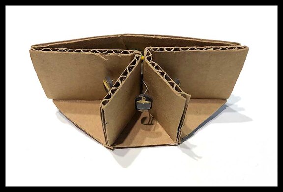
22. Other Sensors and Kit Additions
One of the nice things about the robot is there is room to add more sensors and the MSP432P401 has the memory, processor speed and free pins to handle them. For example, this is a sensor I made for another robot that uses inexpensive photoresistors, also called Light Dependent Resistors (LDRs) which are a type of photocell being used here to detect the direction of the strongest light source. With such a sensor the robot can be programmed to move towards or away from light.
Other sensors for detecting temperature, color, movement and any number of other things could be added. With the encoders and Bluetooth or Wi-Fi, it would be fun to add a pen that moved up and down with a servo to make a robot that drew or wrote messages.
23. The Grand Finale
Batman actually does save Seattle!
I enjoyed the kit, learned a great deal, and thank Element14 and Texas Instruments for allowing me to review it. As always, if members of the community have corrections or suggestions for improvement please let me know in the comments.
13 July 2018 Update: Added a photo that was left out during copy / paste of the original post. No major changes to text.
Links and References:


