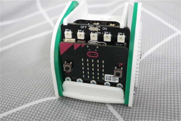
RoadTest: :MOVE mini buggy kit + microbit
Author: mahmood.hassan
Creation date:
Evaluation Type: Development Boards & Tools
Did you receive all parts the manufacturer stated would be included in the package?: True
What other parts do you consider comparable to this product?: Elecfreak Ring:bit Car (cheaper) and GiggleBot Base Kit (expensive with some extra features) are the closest alternate, there are also some other interesting kits available like Robo:Bit Mk2, SparkFun micro:bot kit, Bit:Bot - Robot Kit for Micro:Bit
What were the biggest problems encountered?: Servos are without any feedback control so driving both servos at same speed is little difficult. Also there is no other way to access micro:bit edge connector except Line Following add-on for :MOVE mini.
Detailed Review:
Before we start I want to thank the E14 team for selecting me for this Roadtest and therefore giving me the opportunity to work with :MOVE mini buggy. This is my first review and I had lots of fun doing all the testing and building fun projects.
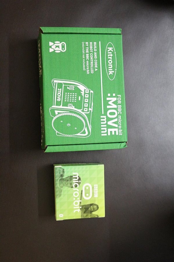
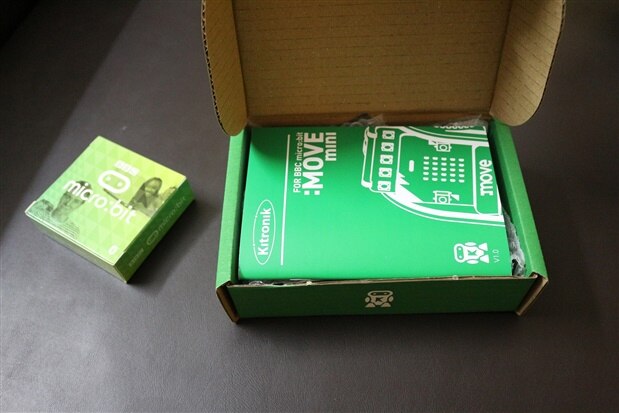
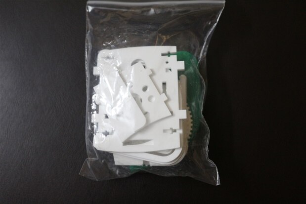
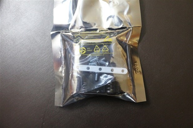
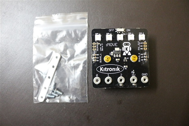
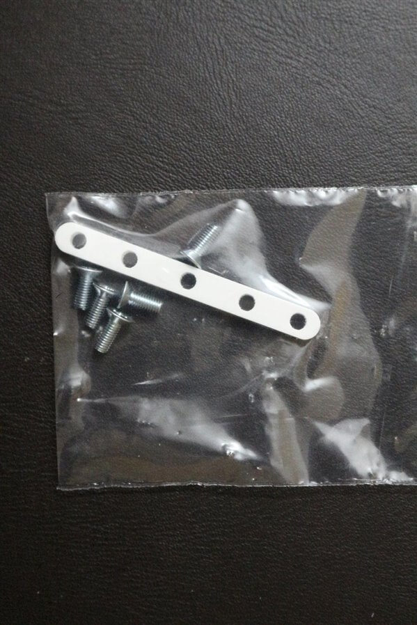
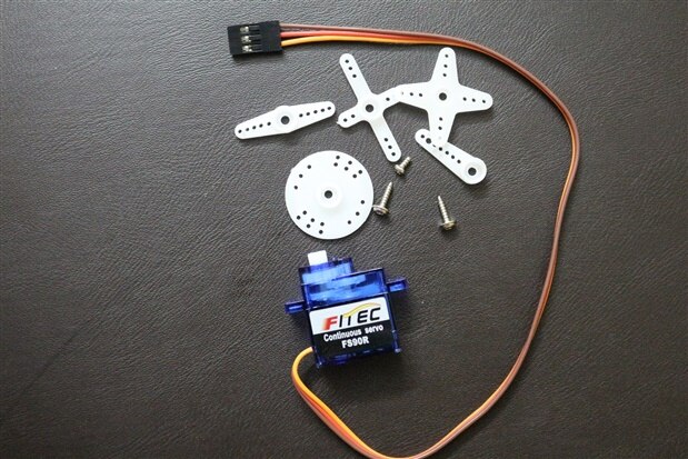
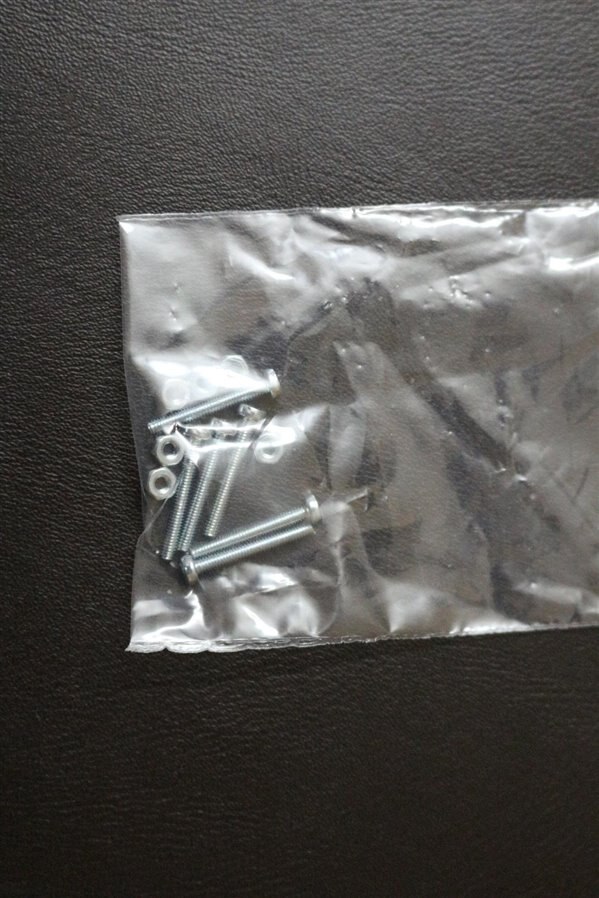
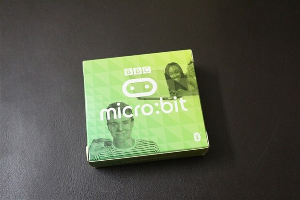
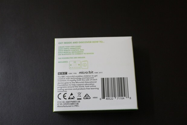
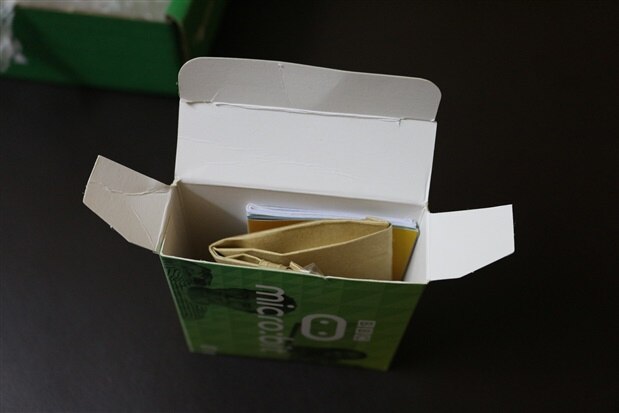
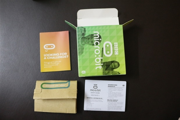
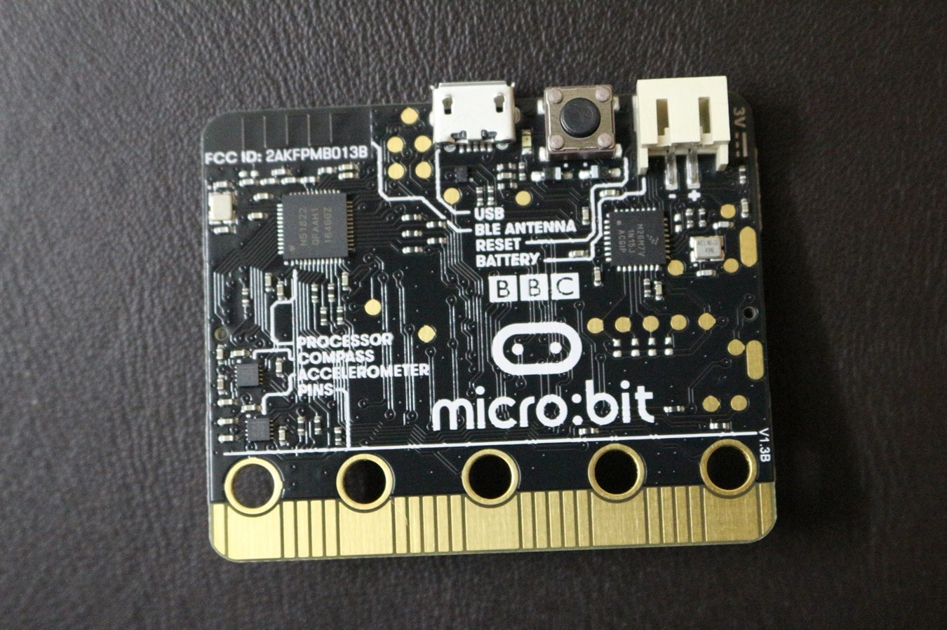
Here is the gallery of unboxing snaps of MOVE mini buggy kit + micro:bit.
| {gallery} :MOVE mini buggy kit + micro:bit |
|---|
IMAGE TITLE: Element 14 Box containing MOVE mini and microbit |
IMAGE TITLE: That how the contents were placed inside Element 14 box |
IMAGE TITLE: Element 14 Box content - MOVE mini and micro:bit |
IMAGE TITLE: MOVE mini box - bottom view |
IMAGE TITLE: MOVE mini box opening and its content view |
IMAGE TITLE: Contents of MOVE mini buggy kit box |
IMAGE TITLE: MOVE mini body parts |
IMAGE TITLE: MOVE mini body parts |
IMAGE TITLE: MOVE mini body parts out of its pack |
IMAGE TITLE: All the MOVE mini buggy body parts |
IMAGE TITLE: MOVE mini buggy servo LITE board pack |
IMAGE TITLE: MOVE mini buggy servo LITE board pack |
IMAGE TITLE: MOVE mini servo LITE pack content |
IMAGE TITLE: MOVE mini servo:LITE board assembly with micro:bit parts |
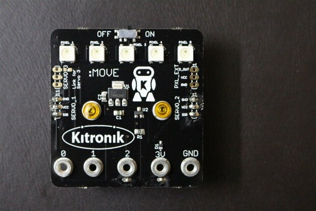
IMAGE TITLE: MOVE mini servo:LITE board front view |
IMAGE TITLE: MOVE mini servo:LITE board back view |
IMAGE TITLE: MOVE mini 2x 360 servo pack |
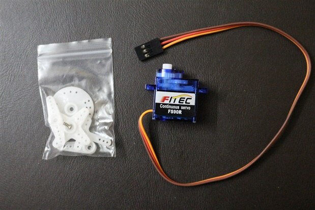
IMAGE TITLE: MOVE mini servo pack contents |
IMAGE TITLE: MOVE mini servo with all its accessories |
IMAGE TITLE: MOVE mini servo trimming POT |
IMAGE TITLE: MOVE mini AAA cells |
IMAGE TITLE: MOVE mini body mechanical assembly parts |
IMAGE TITLE: micro:bit box top view |
IMAGE TITLE: micro:bit box bottom view |
IMAGE TITLE: micro:bit box opening and its content view |
IMAGE TITLE: micro:bit box contents |
IMAGE TITLE: micro:bit box contents with micro:bit out of its paper pack |
IMAGE TITLE: micro:bit front view |
IMAGE TITLE: micro:bit back view |
As you can see in the above snaps that all the contents are packed nicely with foam cushions and Move mini parts are also in a bubble wrap for extra protection.
MOVE mini buggy kit box quality is average as compared to BBC micro:bit. Its body parts are looking strong, cleanly built and with some nice finishing so no sharp edges etc. Both the servos contain all the servo horns even though only one is required for MOVE mini assembly. That is something good and enable user to use these servos in any other project. Servo Lite control board`s components assembly and finishing is almost perfect and also its silkscreen quality is better than micro:bit. The MOVE mini tutorial book has very good paper, printing quality and also its made to last even after some rough use which is perfect for kids. Kitronik deserve the credit for making a perfect guide. Every thing required to assemble and run a first program is explained with detail and images.
These are some links where you can find detail electrical and mechanical specifications;
MOVE mini: kitronik - MOVE mini buggy kit
servo:lite control board: kitronik - servolite control board for MOVE mini
servos: kitronik - FS90R 360 degree continuous rotation servo OR Micro 1.3kg.cm 360 Degree Continuous Rotation Servo FS90RFEETECH RC Model Co.,Ltd.
micro:bit: kitronik - BBC microbit board OR microbit.org
Before starting the mechanical assembly of MOVE mini buggy kit, we need to test few things:
Micro:bit is the heart and brain of this buggy so first thing to do is test if micro bit is working properly or not and also setup our pc so we can program/debug our code (installing the required device driver or any other software if required).
* Here it is supposed that we are already familiar with micro:bit
After testing micro:bit we will test the electronic part of MOVE mini buggy kit. First we will test our servo:lite control board and then we will connect our servos to it to test and calibrate if required.
In MOVE mini it is used to provide power supply to all components (micro:bit, servos and RGB ZIP LEDs) and it connect to micro:bit through 5x screws which also serve as electrical connection between both the boards. It take signals from micro:bit to drive servos and RGB ZIP LEDs. Its is powered by 3x AAA cells
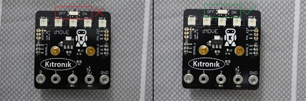
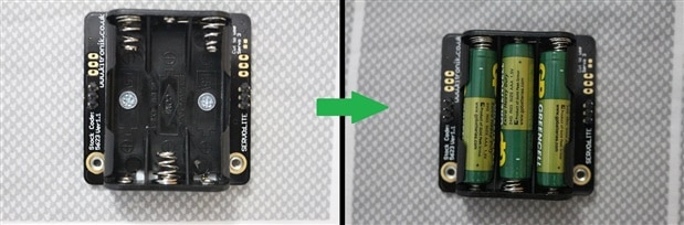
Before start testing the servo:lite control board, first check if on/off switch at off position or not. If power on/off switch is at on position simply turn it off and then insert 3x AAA cells (included in the kit). Now turn on the switch and check the voltage between 3V and GND terminals. Similarly we will also check the voltage between VCC and GND pin of both servo terminals. If we are getting ~ 3.3V (if all cells are new and each cell voltage is around ~1.6V) then our servo:lite is OK and its safe to connect our micro:bit with it.
| {gallery} Servo:LITE control board testing |
|---|
IMAGE TITLE: Before inserting cell turn off the ON/OFF switch |
IMAGE TITLE: Insert 3AAA cell provided with the kit |
IMAGE TITLE: Check the voltage between 3V and GND terminal |
IMAGE TITLE: Check the voltage between GND and VCC pins of Servo_1 terminal |
IMAGE TITLE: Check the voltage between GND and VCC pins of Servo_2 terminal |
Now power OFF the servo:lite control board, remove the cells and then we will connect with our micro:bit with it, to test/calibrate servos and RGB pixels. (user guide page 7)
| {gallery} Assembly the servo:lite PCB |
|---|
IMAGE TITLE: Component required to assemble SERVO:LITE PCB |
IMAGE TITLE: After completing the servo:lite PCB assembly |
IMAGE TITLE: After completing the servo:lite PCB assembly |
IMAGE TITLE: After completing the servo:lite PCB assembly |
After completing the assembly of servo:lite PCB verify the connection between each screw and corresponding ring terminal if its not a proper connecting then that screw might need little tightening.
Before assembling the MOVE mini buggy kite we need to test ZIP LED and servos too and to do that we will program out micro:bit and check each ZIP LED then both servos. (user guide page 8-12)
| {gallery} Testing ZIP LED |
|---|
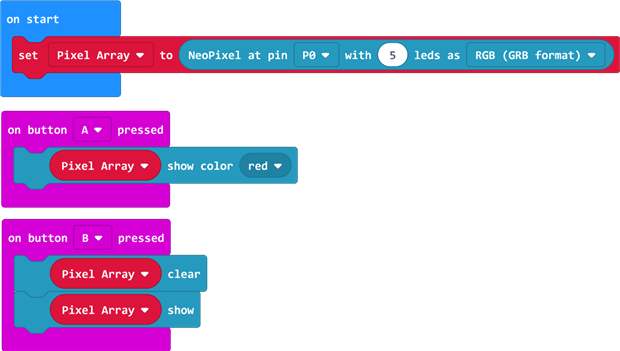
IMAGE TITLE: micro:bit block code to set all zip led to red color on press of button A and off on press of button B |
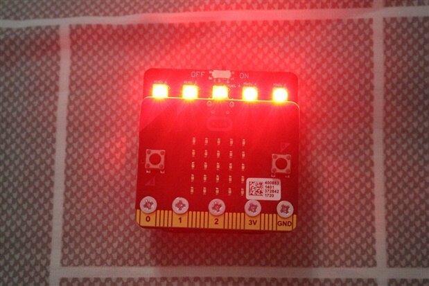
IMAGE TITLE: all zip led to red color on press of button A |
IMAGE TITLE: micro:bit block code to set zip led to 1 and 2 to red color 3 to white color 4 and 5 to blue color on press of button A and off on press of button B  |
IMAGE TITLE: zip led to 1 and 2 to red color 3 to white color 4 and 5 to blue color on press of button A |
IMAGE TITLE: micro:bit block code to set zip led to multi color on press of button A and off on press of button B. Here the code in forever loop will shift the led color onto next led every 100ms |
IMAGE TITLE: Color changing pattern on press of button A |
MOVE mini buggy kit has 2x continuous rotation servos. These are controlled in same way as we control RC servo. We use PWM signal to control it. The only difference between full rotation and RC servo is that PWM signal control its speed rather than its angel while the direction is control in the similar manner. To test and check if any calibration is needed or not we will write a small microbit code and move our servos in both directions at full speed and also stop these while giving the neutral position PWN signal.
.
After testing the basic functionality of ZIP LED we will test our servos and calibrate these if required. In order to test servos we can either use servo pin write block code (as shown in page 16 of user guide) or we can take advantage of kitronik servo:lite extension of micro:bit block/java-script editor. Here we will use both codes to test/calibrate servos. (user guide page 14-16)
| {gallery} Servos Testiing |
|---|
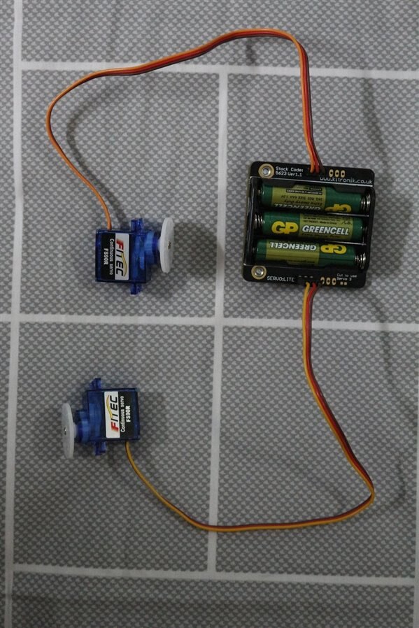
IMAGE TITLE: Connect both servos correctly to the Servo:LITE control board as shown in this image (user guide page 15) |
IMAGE TITLE: Make a code in block editor to test the servos and download the hex file and add the code onto micro:bit |
IMAGE TITLE: Add kitronik extension to simplify the code |
IMAGE TITLE: Make a code in block editor to test the servos and download the hex file and add the code onto micro:bit |
IMAGE TITLE: After Loading either of the hex file on press of button A both servos will start moving in one direction at full speed and on press of B these will change the direction and when we will press both A & B together these will stop and also no sound will be coming from these if both servos are calibrated properly. |
After running the servo testing code we notice that one servo is moving slowly even when both servos should be stopped at neutral position otherwise both are working OK. The slow movement or any sound coming from a servo during neutral position is not a big issue we can solve it by using the trimmer on back of each servo. If no sound or movement is there during neutral position of servo then we can skip this step. (user guide page 17)
| {gallery} Servos Calibration |
|---|
IMAGE TITLE: Using a small screw driver move it slowly in either direction till the servo stop moving and also there is no sound coming from it. |
After successfully testing the servo:lite board and servos we can start assembling our MOVE mini buggy. In the gallery below different step of assembly are shown:
| {gallery} :MOVE mini buggy kit Assembly |
|---|
IMAGE TITLE: All the components required to complete the assembly of MOVE mini buggy |
IMAGE TITLE: Place both servos on base plate as shown in this image  |
IMAGE TITLE: put the nut and screw in these holes |
IMAGE TITLE: Attach the side part over servo and tight the screw similarly attach the second side part |
IMAGE TITLE: After installing the side parts snap in the pen holder |
|
IMAGE TITLE: Prepare the outer side panel as shown above |
IMAGE TITLE: Attach the outer side panels |
IMAGE TITLE: After placing the outer side panel in place tighten the screws |
IMAGE TITLE: Similarly install the other outer side panels |
|
IMAGE TITLE: Attach a wheel to each servo using given screws |
IMAGE TITLE: Now connect the servo to the servo:LITE board as shown above |
IMAGE TITLE: Clip the servo:LITE assembly under the hook of inner side panels |
IMAGE TITLE: Tuck in the loss servo cable in between side panels |
IMAGE TITLE: Snap in the :MOVE T in-front of micro:bit to secure it |
IMAGE TITLE: Complete :MOVE mini buggy assembly with electronics |
| {tabbedtable} Tab Label | Tab Content |
|---|---|
| Testing ZIP LEDs 1 |
|
| Testing ZIP LEDs 2 |
|
| Testing ZIP LEDs 3 |
|
| Servos Testing |
|
| Servos After Calibration |
|
| Demo After Complete Assembly |
|
Assemble it for the first time is not too easy and you have to be little patient but after assembling few times it get easier and you also discover few tricks to attach these screws and nuts. But It is definitely FUN and some time you laugh at yourself when you don't give proper attention to the manual and assemble it in a wrong way and then you have to do it again from the beginning. Only slightly difficult part in its assembly is holding those tiny nuts in their slots properly. Overall the testing and assembly of MOVE mini buggy is not a very difficult task. There were some minor difficulties/issues and these can be improved/solved very easily by doing a minor adjustments in the design of kit.
After successfully completing the assembly its time to see it in action.
Here are few fun projects that I made to test MOVE:mini buggy kit capabilities and its user friendliness.
| {tabbedtable} Tab Label | Tab Content |
|---|---|
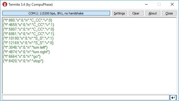
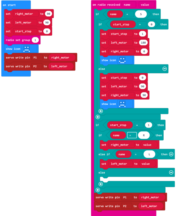
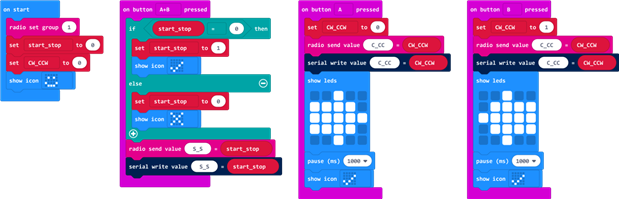
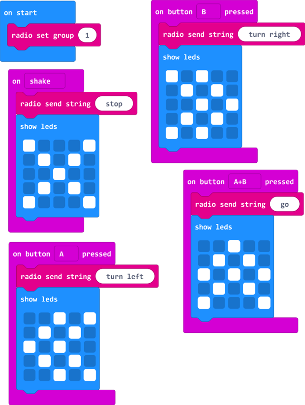
Radio Control | Another micro:bit BBC is required for wireless radio control. One can easily built radio control buggy and also can use onboard compass and accelerometer of remote micro:bit to add motion control. For radio control transmitter and receiver should be set at same radio group. Here is a little code for receiver side that i used to to debug radio transmission. Simply flash the following code onto receiver micro:bit and monitor the received radio data using serial communication. Radio Debug Code:
Debug Result:
Transmitter Code:
Receiver Code:
|
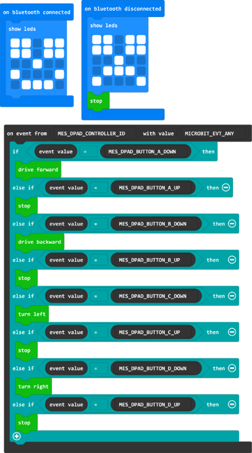
| Bluetooth Control | Using Kitronik App: Kitronik App for android phones can be downloaded from HERE and its help can be found HERE. Its fairly simple to use that app to remotely control the buggy. In order to pair it with micro:bit reset button is also required to be pressed along with button A and button B (Bluetooth pairing Guide). When servo:lite board is assembled with micro:bit, the reset button become inaccessible so instead of pressing reset you can simply power off and then on while holding down both A and B buttons. ZIP leds cannot be used with Bluetooth communication due to micro:bit limitations.
Code and more details are available HERE. |
| Drive in a Straight Line | Driving it in a straight line is little bit tricky and can be frustrating because you have to program micro:bit again and again with different PWM values to move it in a straight line.Because both servos run at different speed for same PWM value and need to be adjusted accordingly to drive MOVE:mini in a straight line. Here is the little code that I used to adjust the PWM values on the go instead of programming it several times. Transmitter Code:
Receiver Code:
At start this code simply run both motors at full speed then you have to see either its going right or left and then adjust the corresponding motor's PWM value by pressing button A or B of transmitting micro:bit till it start moving in straight line. Now save the current PWM values of each motor and use these values for future codes to drive in a straight line. |
| Draw a circle | Drawing a circle using MOVE:mini is the one of the easiest thing that u can draw. To draw a complete circle with one motor at rest and other at full speed, only thing that needed is the time required to completely draw a circle. You can also draw the circles of different sizes by driving both motors at different speeds instead of using only one motor. Transmitter Code:
Receiver Code:
Result:
. |
| Draw a square | After Driving it in a straight line and Drawing a circle, it is fairly easy to draw a square or rectangle. Code:
Result:
|
| Bump and Spin | MOVE:mini buggy can be used to detect obstacle in its path. The trick to detect obstacle is very simple > bump into an obstacle > use onboard accelerometer to detect sudden deceleration > turn right or left and keep moving. Code:
|
| Dynamic Turn Indicators | There is a fun example of dynamic indicators similar to several modern cars on kitronik website but it does only work for left side indicator. It look so cool on such a small robot so I modified the receiver code and now it worked for both right and left side indicators. Transmitter Code: I used the same code given at kitronik website (LINK).
Receiver Code:
|
*There is an example of Automatic Headlight given at kitroniks website (HERE). Unfortunately it doesn't work under florescent lights because micro:bit is unable to detect any light unless you are very close to it.
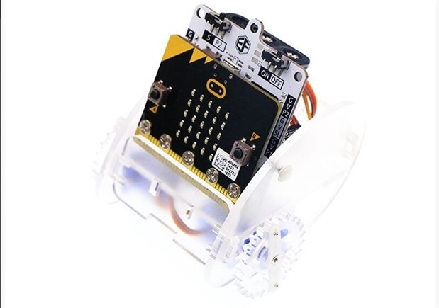
Its is the closest alternate to MOVE:mini which is cheaper but with less attractive built & colors and more importantly without RGB LEDs. Here are some of its images below
| {gallery} ELECFREAKS Ring:bit Car |
|---|
 |
|
|
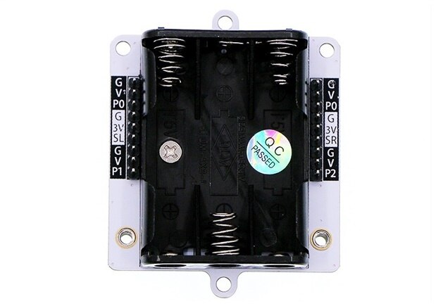 |
 |
 |
Other possible alternates are mentioned at top of this document but those are based on simple DC motors instead of 360 servos.
:MOVE mini buggy is easy to program and attractive mobile robot kit for young kids and electronics enthusiast to learn programming and explore how mobile robots work.
Its charming looks especially color changing RGB lights and ability to draw make kids wonder how it works and you can easily feel the excitement and desire to learn and work with this. And Micro:bit's easy to program capabilities and pre-built codes/extension from Kitroniks is icing on cake for newbies and enthusiasts to learn programming and built fun projects. Overall it is very good robotics kit but one thing that really let me down was unable to simultaneously operate ZIP LEDS and Bluetooth even though its the issue of micro:bit BBC not the kit. So If you want to use it remotely and with ZIP LEDs then you have to buy an extra micro:bit BBC and use its radio function.
I will definitely recommend this to teachers and especially young kids. Because Its a good one to start with but at the same time its little pricey too as it doesn't come with micro:bit BBC. And one of the best thing about it is one can also use its Servo:LITE board and 360 servos in his own robotics or any other project.
Here are some suggestion to make it more user friendly and even more fun without any major change. Images are also shared below for better understanding.
1: One thing that really need to be changed on highest priority is thickness of spacer between micro:bit and servo:lite board. When I first assembled servo:lite PCB and taking its snaps I saw a little bend in my micro:bit. Even though it worked perfectly fine but bend in small size PCB with lots of small components can be dangerous. After inspection I found the reason of that bend. The height of 3V power connector on micro:bit is 5.5mm and combined height of spacer and PCB mounted screw nuts is ~5mm that ~0.5mm difference was the cause of that bend and unnecessary stress on micro:bit.
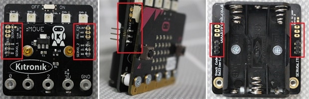
2: Servo:LITE board is designed to work with micro:bit after attaching to it using screws. And If we look at its servo ports silkscreen then it is printed on front side only. After attaching it to the micro:bit its very difficult to read pins function. Even though after using it for a while you can remember it but it will be a big help if pins functions or GND indication is mentioned on the back side of it too.
3: ON/OFF switch is very small in size and also it is sliding switch. So when you use it in fully assembly buggy its little difficult to slide it and you have to hold buggy firmly to do so. It will be much easier to turn it on/off if it is replace by simply latching push button.
4: There is no power level indicator so you have to remove the Servo:LITE assembly from buggy and only then you can measure cells voltage. But it can be made much easier for the user to measure cells voltage using multi-meter in fully assembled form by rotating the Cells holder 180 degree and mentioning the corresponding positive and negative terminals of cells holder.
5: After tightening all screws the inner side panels which are also holding servo motors, bend a little and reason of these bends was rear side panels nuts. And it also made the pen mounting plate a little loose. This problem can be solved by adding a little notch in inner side panel.
6: There is one suggestion for :MOVE mini guide too. Many people complain that after attaching micro:bit to servo:lite board you can not access reset button. Even though turning it off then on will also reset it. So It can be mentioned in servo:lite PCB assembly section that you can reset it by turning it off then on too because lots of its user are kids and newbies and don't know much about controllers.
| {gallery} Suggestion For :MOVE mini buggy Kit |
|---|
IMAGE TITLE: Little Bend in Micro:Bit BBC |
IMAGE TITLE: Reason of bend in Micro:Bit BBC |
IMAGE TITLE: Micro:Bit BBC Mechanical Drawing showing 5.5mm height of 3V battery connector |
IMAGE TITLE: Servo:LITE PCB front silkscreen become invisible and difficult to find pin function from back |
IMAGE TITLE: Servo:LITE PCB voltage measurement from Cells Holder terminal And Rotating 180 Degree will make it easier to measure cells voltage |
IMAGE TITLE: Reason of Bend in :MOVE mini side panels |
micro:bit serial and CMSIS-DAP drivers: https://os.mbed.com/handbook/CMSIS-DAP-MDK
All the hex files are attached.