RoadTest: MyIoT: Infineon Shield2Go Boards for IoT
Author: himanshu_rangadhol
Creation date:
Evaluation Type: Development Boards & Tools
Did you receive all parts the manufacturer stated would be included in the package?: True
What other parts do you consider comparable to this product?: Launch XL RM42 ti board ( ARM M0), ARDUINO NANO( as I was coding mostly on Arduino IDE it was comparable for most of the results with these Infineon boards)
What were the biggest problems encountered?: 1. The header pins were big hassle to work with. Took sometime to figure out how they fit in!(The female header pins won't fit into any of the boards). 2. XMC1100 2Go board was getting heated up pretty badly at times!
Detailed Review:
Hello,
First of all huge thanks to element14 and Randall Scasny rscasny for providing this great opportunity. I received the package bit late due to some confusion, never the less the boards reached safely and well packed.
Received Package
Here is what all i received in the complete package,
1. XMC1100 Boot Kit - 1 Unit
2. XMC2Go - 1 Unit
3. DPS310 Pressure Shield2Go - 1 Unit
4. TLI4970 Current Sense Shield2Go - 1 Unit
5. TVL493D 3DSense Shield2Go - 1 Unit
6. WeMos D1 mini V2 - 1 Unit
7. Header pins (Both male and female connectors)
8. Shield2Go Adapter - 1 Unit

Working with Arduino IDE
Most of the time I prefer to work with Arduino IDE as it is easy to test the product in the initial stages. The advantages with Arduino IDE is
1. Embedded Coding is very simple.
2. has huge community behind for any kind of support.
3. Comparing with Arduino Boards is easy.
The first thing as anyone would do I connected the XMC boot kit to my laptop using a USB cable. Guess what it didn't work. Best part was at the bottom of roadtest page they have given a GitHub link for software libraries and Arduino IDE, it helped alot!.
https://github.com/infineon link for all the boards
This GitHub page has almost everything we need to start working with XMC boards.
https://github.com/Infineon/XMC-for-Arduino link for adding library for arduino IDE for XMC boards ( includes all the boards in XMC series)
If you follow step by step according to the page this is the last step before getting started to set up the environment for infineon boards in Arduino IDE.
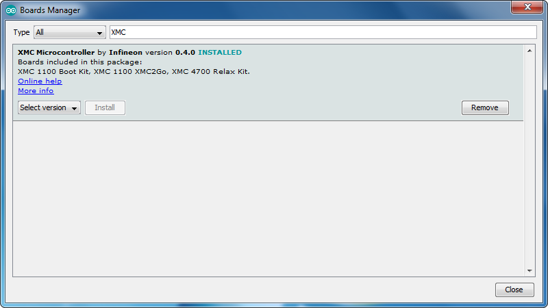
I wrote a simple program and it compiled without any error! but when I tried to upload the code I got an error! went back to the GitHub page and checked I had forgotten to add the J-link library. As I am used to Arduino IDE first thing I did was to check whether the board is recognized in the COM ports and it was recognized. So this error took me back to the GitHub page.

So after installing the J-link libraries I was able to upload the code into the XMC boards.
Now though the boot kit is compatible with Arduino shields the pins are completely different than to the Arduino Uno board (Except the power pins). So next two images are quite important if you want to code for these boards on Arduino IDE. They have almost all the data and well put out diagram without raising further confusions.


General Blink and Serial Debugging Test
As the XMC1100 has 6 user definable general purpose LEDs on the board it self, its quite interesting and fun way to start exploring the board.
Example code for bootkit :(FOR BEGINNERS)
/*
* LED BLINKING TEST FOR THE XMC1100 BOOTKIT
* THIS BOARD HAS 6 USER DEFINABLE LEDS
* THE PINS ARE DEFINED IN THE OFFICIAL INFINEON PO RELEASED FOR ARDUINO IDE ON GITHUB
*
* DEVELOPER: HIMANSHU RANGADHOL
*/
int led1 = 26; //this pins are defined in the PO released by infineon
int led2 = 27;
int led3 = 0;
int led4 = 1;
int led5 = 2;
int led6 = 31;
void setup() {
// initialize 6 LED pins as an output.
pinMode(led1, OUTPUT);
pinMode(led2, OUTPUT);
pinMode(led3, OUTPUT);
pinMode(led4, OUTPUT);
pinMode(led5, OUTPUT);
pinMode(led6, OUTPUT);
}
// the loop function runs over and over again forever
void loop() {
digitalWrite(led1, HIGH);
delay(1000);
digitalWrite(led1, LOW);
delay(1000);
digitalWrite(led2, HIGH);
delay(1000);
digitalWrite(led2, LOW);
delay(1000);
digitalWrite(led3, HIGH);
delay(1000);
digitalWrite(led3, LOW);
delay(1000);
digitalWrite(led4, HIGH);
delay(1000);
digitalWrite(led4, LOW);
delay(1000);
digitalWrite(led5, HIGH);
delay(1000);
digitalWrite(led5, LOW);
delay(1000);
digitalWrite(led6, HIGH);
delay(1000);
digitalWrite(led6, LOW);
delay(1000);
}
XMC1100 2Go has only two user definable LEDs. So you will get the pins for arduino on PO for XMC2Go.
All the required data sheets and other details are available on Infineon website.
for XMC1100 bootkit: https://www.infineon.com/cms/en/product/evaluation-boards/kit_xmc11_boot_001/
for XMC2Go1100: https://www.infineon.com/cms/en/product/evaluation-boards/kit_xmc_2go_xmc1100_v1/
Serial Debugging
Shields Interfacing:
The initial problem was to find the right female header pins for the XMC2Go as the default sent pins were no where closer to fit in the board. Already a predefined library is available on GitHub for these sensors for the Arduino IDE.
DPS310 Pressure Shield2Go
GitHub Link: https://github.com/Infineon/DPS310-Pressure-Sensor
Other link: https://www.arduinolibraries.info/libraries/dps310 (I didn't try this library, just found this when i was searching for Arduino libraries)
The DPS310 is a miniaturized digital barometric air pressure sensor with a high accuracy and a low current consumption, capable of measuring both pressure and temperature. The internal signal processor converts the output from the pressure and temperature sensor elements to 24 bit results. Each unit is individually calibrated, the calibration coeȄicients calculated during this process are stored in the calibration registers. The coeȄicients are used in the application to convert the measurement results to high accuracy pressure and temperature values. Sensor measurements and calibration coeȄicients are available through the serial I2C or SPI interface.
Key Features:
This initially gave multiple issues, but later worked precisely.
TVL493D 3DSense Shield2Go
GitHub Link: https://github.com/Infineon/TLV493D-A1B6-3DMagnetic-Sensor
The 3D magnetic sensor TLV493D-A1B6 offers accurate three-dimensional sensing with extremely low power consumption in a small 6-pin package. With its magnetic field detection in x, y, and z-direction the sensor reliably measures three-dimensional, linear and rotation movements. Applications include joysticks, control elements (white goods, multifunction knops), or electric meters (anti tampering) and any other application that requires accurate angular measurements or low power consumptions. The integrated temperature sensor can furthermore be used for plausibility checks.
Key features are 3D magnetic sensing with a very low power consumption during operations. The sensor has a digital output via 2-wire based standard I2C interface up to 1 MBit/sec and 12 bit data resolution for each measurement direction (Bx, By and Bz linear field measurement up to +-130mT).
Key Features:
TLI4970 Current Sense Shield2Go
GitHub Link: https://github.com/Infineon/TLI4970-D050T4-Current-Sensor
The TLI4970 is a high-precision current sensor based on Infineon's proven Hall technology. The coreless concept significantly reduces footprint compared with existing solutions. TLI4970 is an easy-to-use, fully digital solution that does not require external calibration or additional parts such as A/D converters, 0 pAmps or reference voltage. It thus significantly reduces overall implementation efforts as well as PCB space and cost.
Key features:
I interfaced a flex sensor to the this current sensor and the results were phenomenon. Advantages were
1. One of my ADC pin was free now.
2. No fear of damaging the board because of high current variation caused by the flex sensor (As the resistance varies enormously in flex sensor)
3. Very accurate data.
Precautions: Make sure the current sensor is along with the path of the flex sensor and don't use the voltage divider circuit as used in traditional method)
WEMOS D1 Mini
Apart from providing the WLAN communication for the XMC1100 boards i didnt find any other special usage for this roadtest. Though ESP8266 is a powerfull and widely used MCU for IoT porjects, for this road test most of my concentration was on XMC boards.
Future Plans and conclusion
As I am still exploring these boards, I would love to implement these into my research projects and test out the capabilities with respect to PWM, ADC and higher data latency for further communications.
These are pretty rugged and versatile boards. only problem I faced was connecting through those header pins. Also XMC2Go1100 board was getting heated up pretty badly. The main advantage i found is compatibility of these boards with arduino IDE which is a great thing! I am still exploring the i2c and spi protocols, so in future i will be uploading more data on this.
I am doing research on tracking the Gross motor actions for special children using frugal science ( the exoskeleton is built using bamboo, for sensing I am using pot, rotary encoders and flex sensor. Basically consuming most of time in understanding and mapping these results to form a standard deducible structure for every action of special children.) So in future I will be uploading these research data.
I am delighted to be a part of this roadtest and there is still plenty more to explore. Surely I will be uploading more data regarding these boards in future.


