RoadTest: Cool Tools: ESR Meter, Capacitor
Author: michaelwylie
Creation date:
Evaluation Type: Test Equipment
Did you receive all parts the manufacturer stated would be included in the package?: True
What other parts do you consider comparable to this product?:
What were the biggest problems encountered?: No issues, product works great for the intended application
Detailed Review:
This RoadTest was originally a blog about Cool Tools, but changed to a RoadTest. Originally, I had planned to make a few measurements with the device and write a short blog about the idea, but now that it is a RoadTest I planned a separate set of tests. Essentially, if I am going to give the device a rating, I feel as though it should be tested. This RoadTest is also late, for which I apologize; I was called into field operations for a month.
Figure 1 shows the PEAK atlas ESR meter. The first thing I noticed was how small it was. It’s not a bad thing – I’m just used to measurement gear being bigger. In fact, the more I used the device, the more I liked its size. The device has tones that play when you’re testing a capacitor. I never got the chance to hear the ‘bad ESR’ tone, but that could be seen as a good thing as I didn’t have a bad capacitor. On the right you can see the supplied alligator clips, which seem to have some sort of gold coating on them - probably for corrosion resistance.

Figure 1: PEAK Atlas ESR meter.
The alligator clips are connected via banana clips, which means you can remove them and put in your own set of probes. These connections are shown in Figure 2.
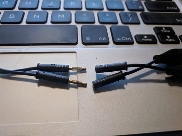
Figure 2: Banana plug connections on the meter.
To really show the size of the unit, here is a picture of me holding the meter while taking a measurement.

Figure 3: Holding the meter while taking a measurement.
I am a Research and Development Engineer, so I like data. First, I chose a bag of 22 uF capacitors I had lying around but did not have a part number. There were 93 capacitors in the bag and I was curious if I would get a Gaussian distribution if I measured them all … so I did. Figure 4 shows the measured distribution. The horizontal axis units are microfarads. Indeed, the distribution is Gaussian.

Figure 4: Capacitance distribution of 22 uF electrolytic capacitors. Horizontal units are microfarads.
The unit also measures ESR, hence the name ... ESR meter. So, Figure 5 shows the ESR distribution for the same set of measurements (horizontal units are ohms). It's an interesting plot, as the distribution seems to be bimodal. Bimodal distributions are usually explained by some interfering phenomenon - I wonder what would cause that in capacitor construction?

Figure 5: ESR values (ohms) for the same capacitors measured in Figure 4.
I had a bag of 39, 33 uF capacitors and tried the same experiment. Figure 6 shows the histogram for the capacitance, and Figure 7 shows the histogram for the ESR. The horizontal units are microfarads and ohms respectively.

Figure 6: Distribution for 33 uF capacitors. Horizontal units are microfarads.
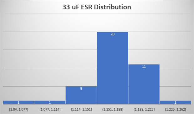
Figure 7: ESR values (ohms) for the same capacitors measured in Figure 6.
Figure 8 & 9 shows the same graphs for a batch of 3.3 uF capacitors. Not great Gaussian distributions, but there is a resemblance.

Figure 8: Distribution for 3.3 uF capacitors. Horizontal units are microfarads.
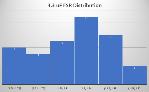
Figure 9: ESR values (ohms) for the same capacitors measured in Figure 6.
At this point during testing I noticed a trend in the data I was taking, so I decided to measure the same capacitor repeatedly and see what the data looks like. Figure 10 shows the trend I had observed, which is a decreasing capacitance. Also note, the ESR had an increasing trend. I'm very curious what could be causing this.

Figure 10: 33 uF capacitor repeatedly measured (uF vs measurement number).
In a rather frank summary, the meter is good and I like it. If anyone has some insight into the cause of the distribution ‘anomalies’ I’d love for you to comment below.


