RoadTest: Microchip AVR-IoT WG Dev Board
Author: tonydbeck
Creation date:
Evaluation Type: Development Boards & Tools
Did you receive all parts the manufacturer stated would be included in the package?: True
What other parts do you consider comparable to this product?: There are a number of IoT development kits out there with similar functionality. Here are is a selection I have come across: || Node MCU Boards - These are a low cost open source board that use the ESP8266 wifi module. They can be programmed using a language called Lua or can be set up to use the Arduino tool set. || Particle boards (Argon,Boron,Xenon,Photon and Electron) - These are very small boards similar to the Node MCU boards. The boards are designed to work seamlessly with the Particle Device Cloud. Particle provide everything from the IDE to develop the application to the actual application hosting. There is a very good level of documentation available on their website as well. A particle photon board would be my second choice next to the AVR-IoT board. || Pycom WIPY 3.0 - This is an ESP32 based board and has WiFi, BLE and is programmed with MicroPython. Pycom also make the SiPy which is very similar, but also supports Sigfox - great if you want long range coverage || Samsung ARTIK Boards - Samsung have produced a range of boards that use their ARTIK WiFi and Bluetooth modules. || TI SimpleLink CC3200 Evaluation Board - This is a packaged IoT board referred to as a 'SensorTag' that houses the TI WiFi module and 9 low power MEMS sensors. || ST X-Nulceo-IDW04A1 - This is an add on board that will plug into the popular ST Nucleo development kits to add WiFi functionality.
What were the biggest problems encountered?: The biggest issues I had was trying to send data back to the board due to the lack of documentation to do this and no software examples. Another issue I noticed was the temperature was a few degrees higher than the ambient temperature. I believe this was due to heat produced by the board itself. A way to solve this could be to utilise the low power functionality and send data every 10 or more seconds instead of every second.
Detailed Review:
First of all, a big thanks to rscasny / element14 and Microchip for giving me the opportunity to participate in this RoadTest. It is my first Road Test and has been a great way to kick start my participation in the Element 14 community. I would recommend anyone to give a Road Test a go!
I will do my best to write up a good report - I have been looking through lots of reviews, both good and bad, to try and determine the magic formula of what makes a good review.......... I am afraid to say I didn't figure out the magic ingredient!  But, I have noticed, that something easy to read that gets the point across without just re-writing the manufacturers data sheet seems to go down well..... so I will see what I can do and try my best! Will be great to get some feedback on the
So what motivated me to apply for this Road Test? Well, I have seen many Road Tests advertised before on Facebook and always thought about applying. When I saw this one, I immediately thought of an application I could use it for, so decided to apply.
My idea was to link it with my automated central heating system and use it as a portable room temperature controller. My central heating control system currently uses a Raspberry Pi running Node-Red to connect to the cloud and allow control from my phone. I have a couple of DS18b20 sensors around my home to measure the temperature upstairs and downstairs - these temperatures are read in by the Pi which then controls my central heating based on the temperatures and temperature setpoint.
Currently, the sensors I am using are in fixed locations - with this board, as it is wireless and portable, I intend to control the heating based on the temperature of whatever room the board is placed in.
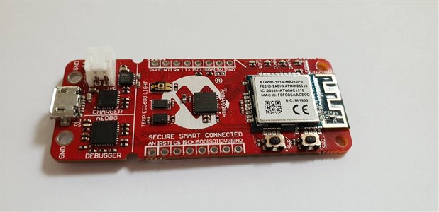
The AVR-IoT board is a development board aimed at the Internet of Things. It has an on board Temperature and Light sensor for which the measurements are sent to the Google Cloud IoT platform every second.
It has a built in Debugger and Programmer that supports drag and drop programming, debugging and access to the built in MCU UART.
The user manual describes it as the following:
The AVR-IoT WG development board is a small and easily expandable demonstration and development platform for IoT solutions, based on the AVR® microcontroller architecture using Wi-Fi® technology. It was designed to demonstrate that the design of a typical IoT application can be simplified by partitioning the problem into three blocks:
• Smart - represented by the ATmega4808 microcontroller
• Secure - represented by the ATECC608A secure element
• Connected - represented by the WINC1510 Wi-Fi controller module
Microchip have also published a YouTube video that gives a nice introduction:
Here are some key questions I will try and answer in this RoadTest and review in my conclusion.
The main processor for the board is an ATMEGA 4808 MCU
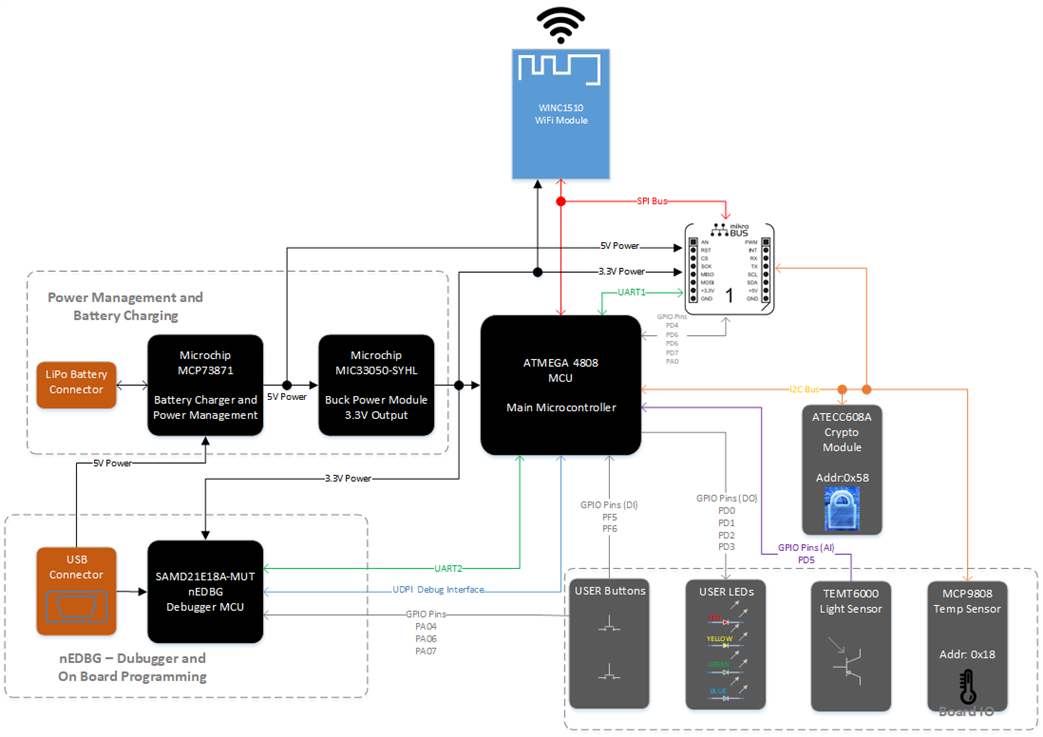
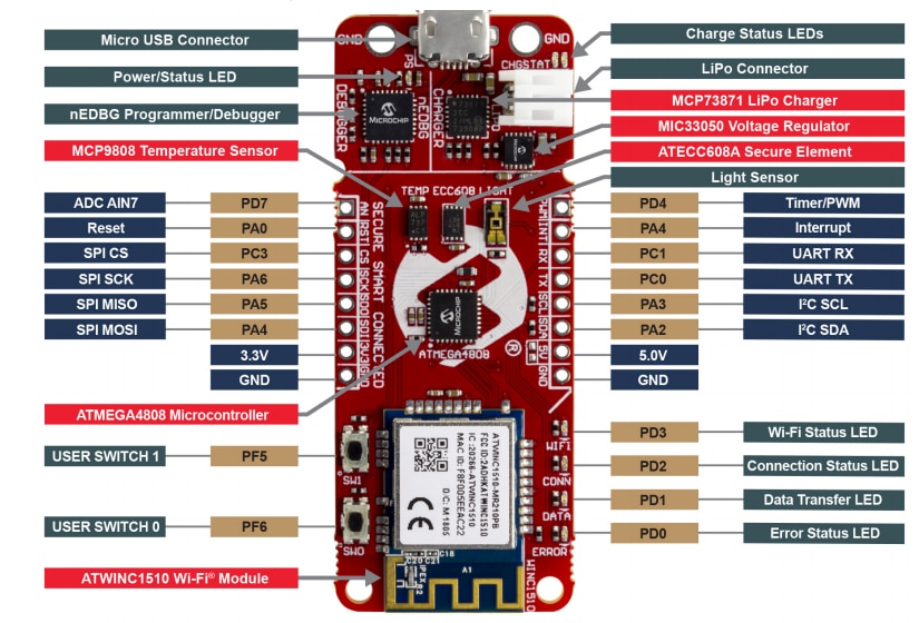
The following is a summary of the components used on the board :
| {tabbedtable} Tab Label | Tab Content |
|---|---|
| ATMEGA 4804 | ATMEGA 4808 - Datasheet
|
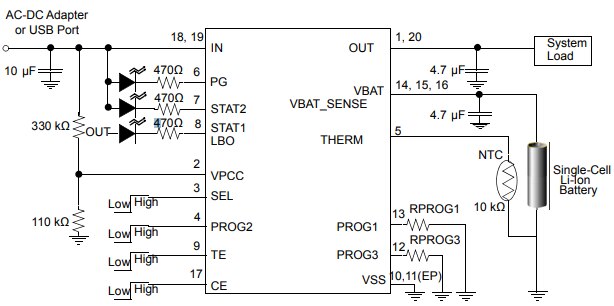
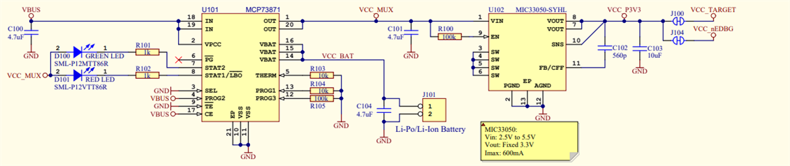
| MCP73871 LiPo Charger | MCP73871 LiPo Charger with Power Path Management - Datasheet
This little IC is a fully integrated power management and Li-Ion battery charging solution for small electronic systems.
It will take power sourced both from a wall AC-DC adaptor, USB ports or from a connected Li-Ion battery. It requires a very low number of components to operate making it great to use on a small embedded board such as this one.
Here is a complete example circuit implementation from the datasheet:
|
| MIC33050 Voltage Regulator | MIC33050 Voltage Regulator - Datasheet
Features
|
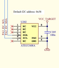
| ATECC608A Security IC | ATECC608A Security IC - Datasheet
This security IC gives this board one of the key differentiating features when compared to other IoT development boards on the market.
It has a number of excellent security features that if used correctly will make a solution based on this very secure with a high resistance to hacks.
One great feature is the key production and management. It is able to create a high quality random private/public key pair where the private key is stored internally and will never be made available outside of the IC. The public key can then be read using functions contained in the cryptoauth library supplied by Microchip. Keeping the private key secured is extremely important in any secure application to ensure the data can't be compromised. In IoT and other products where a security IC is not used but that require secure communications, a private/public key combination needs to be provisioned in a manner where it is possible the private key could be compromised. This IC removes this possibility.
Here are the main features taken from the datasheet:
|
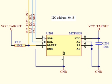
| MCP9808 Temperature Sensor | MCP9808 Temperature Sensor - Datasheet
This is a digital temperature sensor that will measure and convert a temperature of between -20degC and +100degC to a digital word with a typical accuracy of +/- 0.25degC and maximum of +/-0.5degC.
It communicates over a 400kHz 2wire I2C bus.
The key features from the datasheet are:
Here is the Functional Block Diagram taken from the datasheet:
|
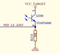
| TEMT6000 Light Sensor | TEMT6000 Light Sensor -https://www.sparkfun.com/datasheets/Sensors/Imaging/TEMT6000.pdfDatasheet
This is simply a silicon NPN phototransistor that is sensitive to the visible spectrum of light.
It is adapted to human eye responsivity and has a wide angle of half sensitivity - +/- 60deg
|
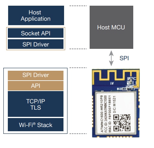
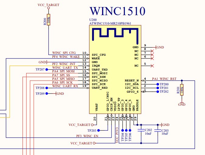
| WINC1510 WiFi Module | WINC1510 WiFi Module - Datasheet | Wi-Fi Network Controller Software Design Guide
This component is a Certified 802.11 b/g/n IoT network controller System on Chip. It abstracts a large portion of the network communications away from the host processor making it much simpler to implement a WiFi base IoT system. It is especially optimized for low power IoT applications.
It contains a fully integrated power amplifier, LNA, switch and power management and printed antenna.
The module hosts the WiFi Stack, TCP/IP and TLS stacks with corresponding API and an SPI driver.
One interesting feature I found that would make this module very appealing for use in Industrial IoT products where the product may be used on networks controlled by large corporations is the support for Enteprise security with WPA/WPA2 (802.1X).
Here is a summary of the features from the datasheet:
|
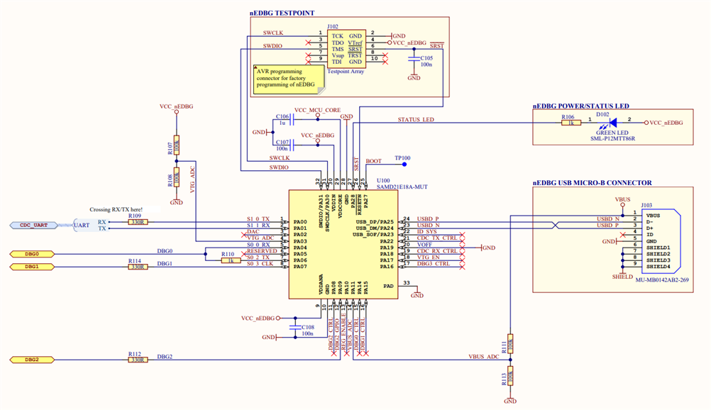
| nEDBG Circuit | nEDBG Circuit
The board features a complete Embedded Debugger that allows on-board programming and debugging. It has a number of interfaces making it very useful!.....
The Embedded Debugger connects to the MCU via the Unified Program and Debug Interface which is an Atmel proprietary 1-wire debug and programming interface.
|
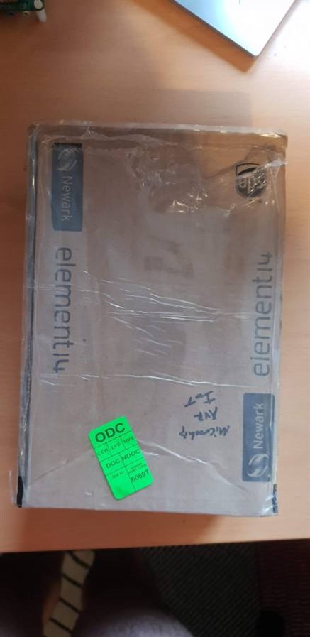
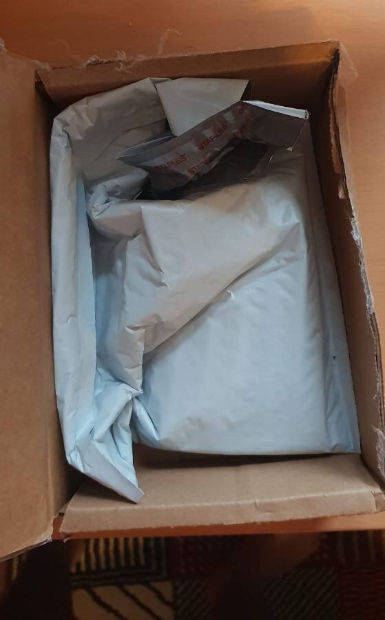
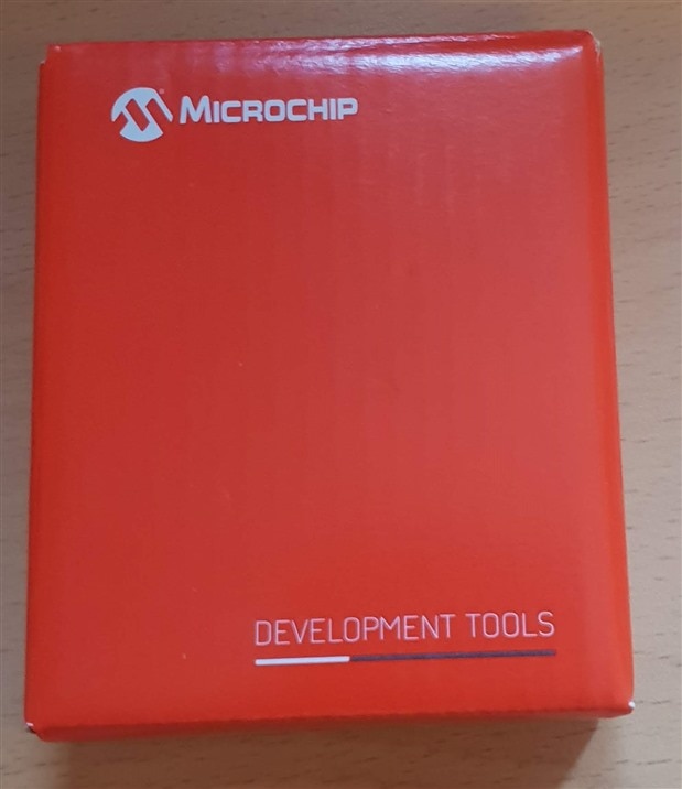
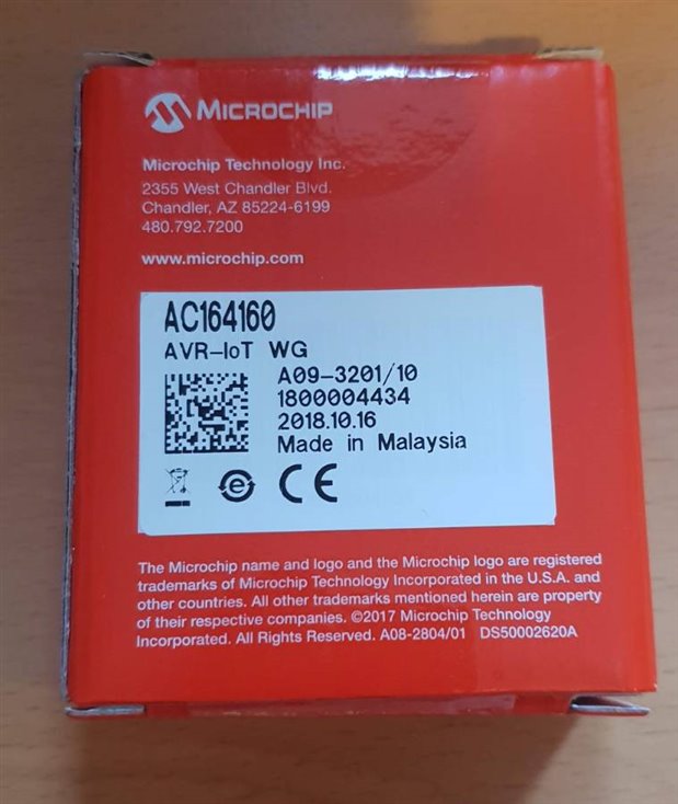
| {gallery} Unboxing |
|---|
|
The board was well protected in the package |
The box that the board came in was nice a compact |
|
The board was protected in a small Anti-Static bag |
The board itself is very compact |
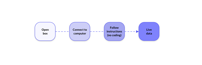
The set up procedure of this board straight out of the box is exceptionally easy. The quick start guide suggests it can be set up in 30 seconds! I would say this is a little optimistic, but possible. For the average user, it is quite easy to do within a minute or two.
There are 3 methods of connecting the board to your network -

Here are the required steps for method 1:
| {tabbedtable} Tab Label | Tab Content |
|---|---|
| Microchip Instruction Video | Microchip have published a great video on YouTube which gives a really good overview of setting up the board.
They have also published a user manual that takes you through each part of setting up the board and gives an overview of the board |
| Step 1 | Plug the board in to a computer  |
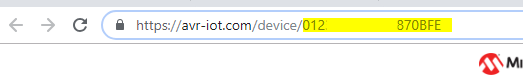
| Step 2 | Double click on the CLICK-ME.HTM link on the CURIOSITY drive This file contains a link to AVR-IOT.com - Microchips sandbox account that will show data received in real time from the board. <meta http-equiv="refresh" content="0; url=https://AVR-IOT.com/device/01235779C93D870BFE"/>  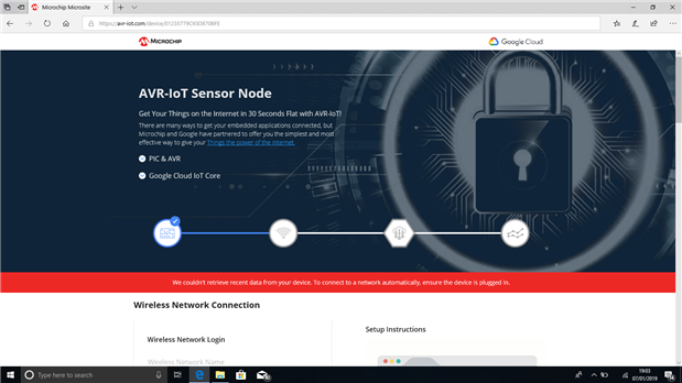 |
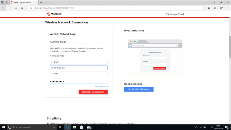
| Step 3 | Generate WiFi Connection File When navigating to the sandbox page initially, as the board is not connected, you are presented with a page to enter the details for a local WiFi network.
|
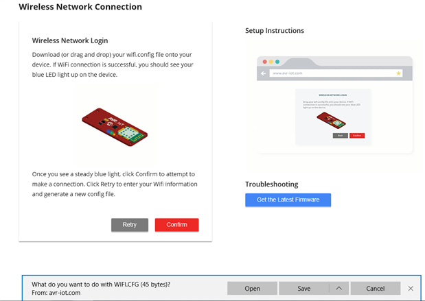
| Step 4 | Once the WiFi details have been entered, you simply click the Download Configuration button to download a small text file containing the WiFi connection details.
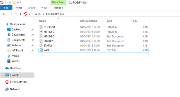
You save this file to the Mass Storage drive which then loads the Wifi credentials into the MCUs EEPROM
|
There are a few options available to configure a demo program manually for the board - one being the Microchip Code Configurator. This tool is actually really nice and easy to use. There is a section in the user guide that takes you through using this tool to set up a demo program and write it to the board.
Here is my experience using it together with the manual to write the program:
| {tabbedtable} Tab Label | Tab Content |
|---|---|
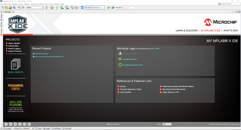
| Step 1 | Step 1 - Open MPLAB X IDE When I first opened MPLAB X IDE, I was presented with the Start Page that has some quick links on the left and allowed me to sign in to my Microchip account. It Also shows a summary of recent projects.
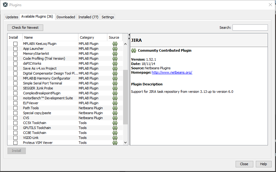
to go to the next step, I had to have the Microchip Code Configurator Add-In downloaded and enabled. To install this, I clicked on Tools->Plugins then choose the Available Plugins tab, found and selected MPLAB Code Configurator, then clicked install.
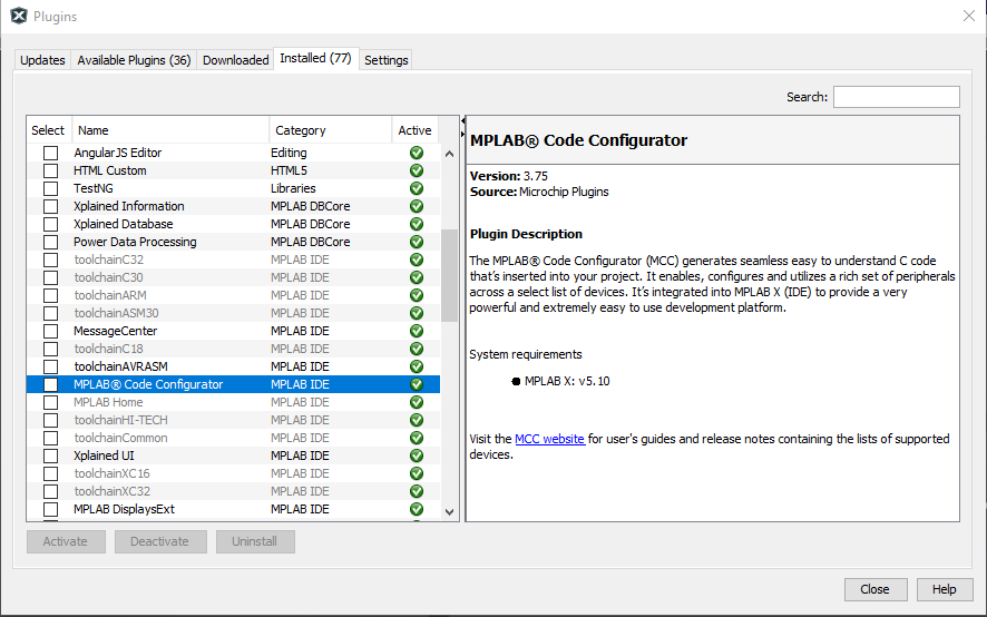
As I had already installed it when I took the screen shots, it does not show up in the screenshot above - instead it shows up in the Installed Tab:
So far, so good!! |
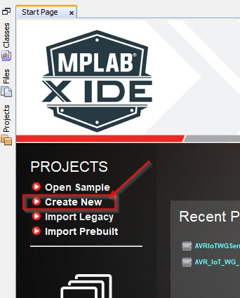
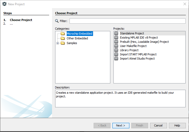
| Step 2 | Create New Project I next clicked on Create New in the Startup Page
and then left the standard selections of Microchip Embedded and Standalone Project
|
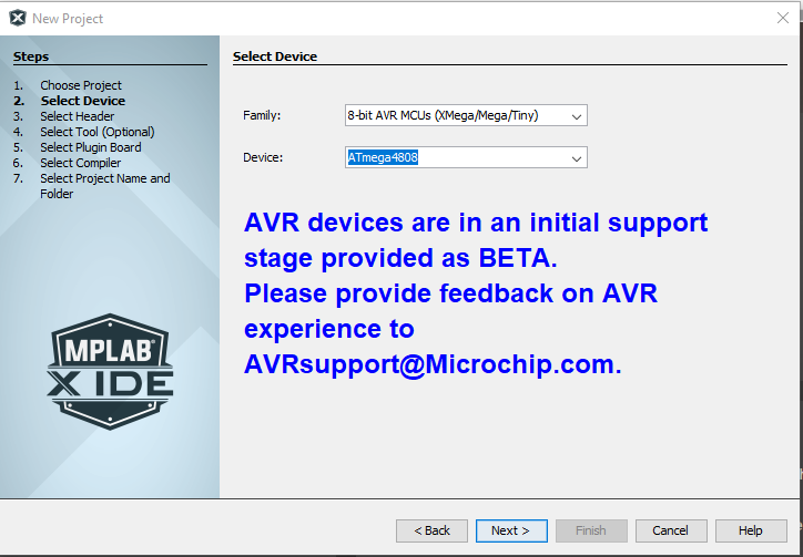
| Step 3 | Choose MCU Next I selected the MCU that is on the board - 8-bit AVR MCUs (XMega/Mega/Tiny) and then ATmega4808
|
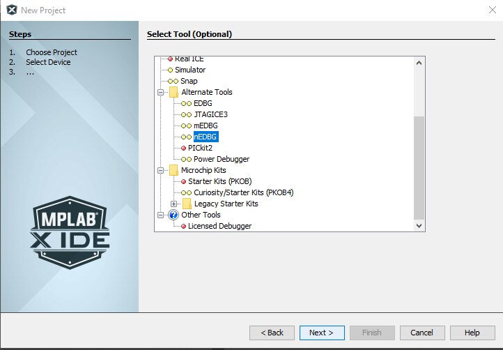
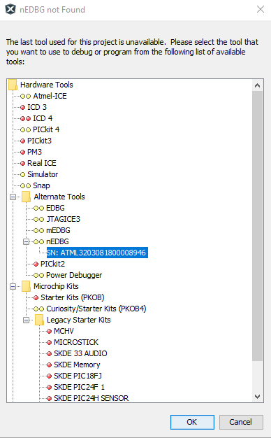
| Step 4 | Choose Debugger/Programmer
I then chose the debugger that is part of the board - the nEDBG. This is under the Alternate Tools tab.
|
| Step 5 | Choose Compiler
At this point, I had the AVR GNU or avrasm2 compilers available to select as I already had these installed. If I had the XC8 compiler installed, I would should this option as well. I chose the AVR GNU compiler / toolchain and clicked Next>
|
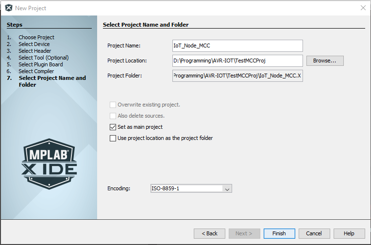
| Step 6 | Choose Project Name
Finally for this part of the set up, I chose the Project Name and Folder location. I called it IoT_Node_MCC for easy future reference:
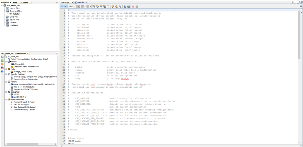
Once this was done, a bare bones project was created - at this point there is only a basic Makefile and a basic project configuration.
|
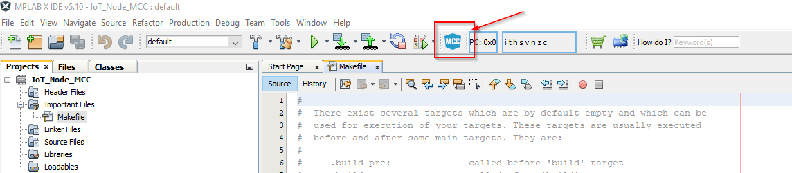
| Step 7 | Begin Configuration of the Project with MCC This is the part where it gets a little more interesting as the MCC tool bulks the project out with all of the necessary functionality........
I clicked on the MCC icon on the tool bar to invoke the configurator....
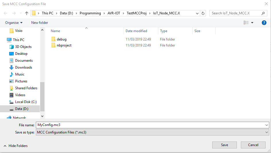
I then got a dialog to save the MCC project file..... for this I chose the default filename and location.
|
| Step 8 | Load the AVR-IoT WG Sensor Node Example
I next picked the AVR-IoT WG Sensor Node example from the Device Resources pane by double clicking on it.
This loaded all of the relevant libraries and configuration for this board.
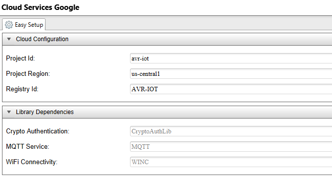
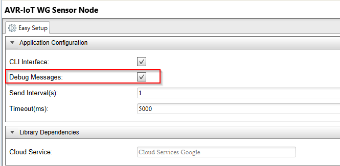
A number of tabs are then presented across the top with various configuration options for a customised application.
For example, the Cloud Services Registry ID can be changed for migrating away from the Microchip sandbox account and to a personal cloud account.
In the AVR-IoT WG Sensor Node tab, I selected the Debug Messages option as this was initially off. For this part, I left all of the other settings unmodified.
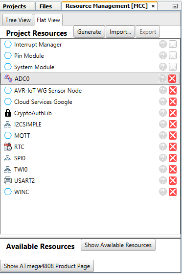
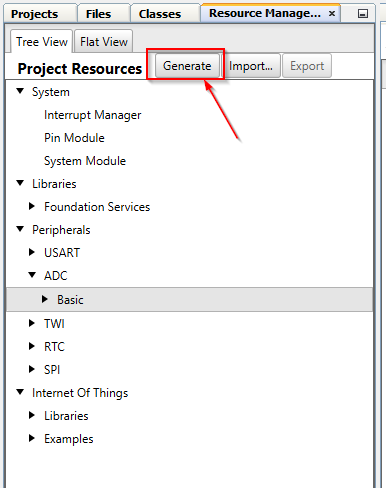
You can also navigate to the different settings in the Project Resource Pane, either in a Tree view or Flat View
|
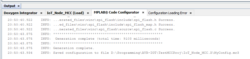
| Step 9 | Generate the Code I now clicked the Generate button in the Project Resources pane to create the code from the MCC project set up.
Once complete, I had a Generation Complete message in the MPLAB Code Configurator status pane.
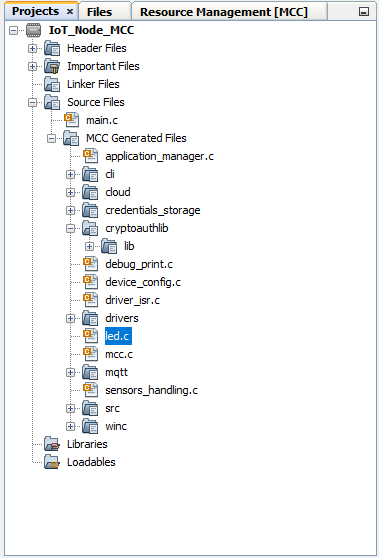
To check the file generation, I had a look at the Project Tree Pane where I could see the various project files.....
I thought the folder organisation is actually pretty good - it is well structured and easy to navigate. |
| Step 10 | Change the Optimizations As per the manual, the code optimization needs to be changed for the code to run at the optimal level. To do this, I right clicked on the top level project folder and selected properties.
As I only have the AVR compiler installed, I selected avr-gcc on the left hand side, then chose Optimization under Option categories and selected s for the optimization level. This optimizes the project favouring size.
|
| Step 11 | Building and Loading Building and loading the project is very simple - you simply click the Make and build icon....
and then chose Make and Program Device Main Project.
I was asked which debugging tool I wanted to use - my board was already plugged in, so it showed up with the serial number in the list under nEDBG....
I selected this, click OK - The compiler then compiled the program, once it was compiled it was automatically loaded to the board. |
Out of the Box, the board connects straight to the Microchip sandbox account and publishes data - which is great to get started, but to go further and really get the most out of the board, you need to migrate the connection to your own private account. I would say this is a relatively easy task, but you do need to take care to follow the instructions exactly. There is a shortcut to start the process off at the bottom of the Microchip Sandbox account webpage.......

The Graduate link takes you to a GitHub page hosted by Leverege who are a company specialising in IoT technologies. They have worked with Google and Microchip to provide a Google Cloud based solution that integrates the AVR-IoT board with the Google Cloud.
This really simplifies setting up all the 'back-end' stuff to get a working Cloud solution in place. The only downside is that a lot of the set up and configuration is hidden away as it is all automated. Also I could not find any detailed information explaining the project and taking you through how it takes data published by the board, places it in the Firebase real time database and then shows it on a graph on a web page. It would be nice to at least have a manual of some sort specific to this board that explains all of the google cloud services that are used and how they fit together to make the complete solutions work.
I guess the criteria that Microchip / Google / Leverege have tried to fulfill is to make a complete solution that is quick and relatively easy to deploy - but I would say this is at the expense of flexibility.
| {tabbedtable} Tab Label | Tab Content |
|---|---|
| Step 1 | Follow Link to Leverage GitHub
I first clicked on the Graduate button at the bottom of the Microchip Sandbox webpage which takes you to the Leverage GitHub page that hosts the instructions and set up files for this board.
This link took me here:
Leverage have created a set of videos that take you through the process which is very useful. They also have also described the process. I will document the steps I took here..... |
| Step 2 | Sign Up / Configure Google Cloud If you are not already signed up to Google Cloud, then you will need to do this before anything else. In my case, I had already set up an account before the Road Test started. One of the nice things about Google Cloud is that you get a bunch of credits for free when you sign up and configure billing. This allows you to experiment without landing a big bill.
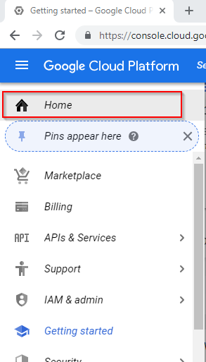
The address for the Google Cloud Platform Management Console is: console.cloud.google.com |
| Step 3 | Create Google Cloud Project Within the Console, I first clicked on Home to open the Dashboard
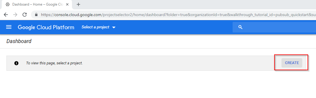
and then clicked on CREATE to begin a new project.
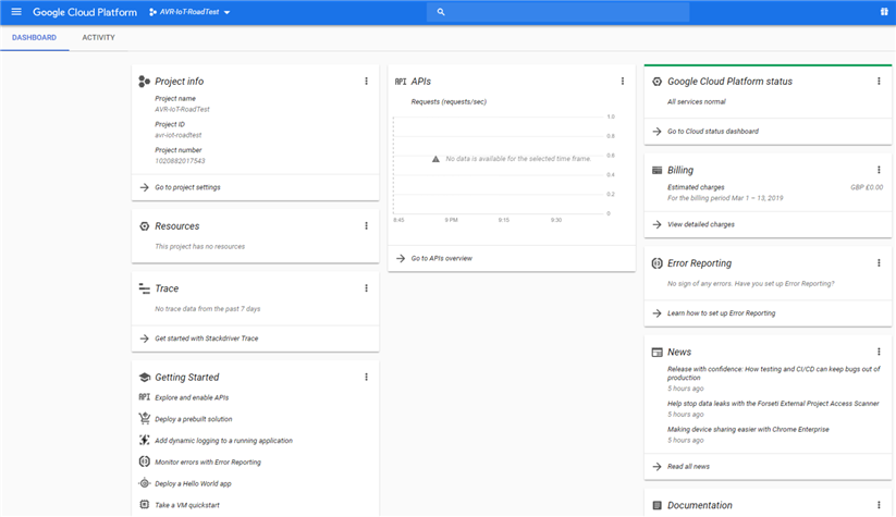
I then gave my new project a name and clicked CREATE.
It took a few seconds to create the project, but once it was created I was presented with a range of widgets on a dashboard to give a project overview
On the Leverage instructions, it states that you need to enable billing for the project. In my case as I am the billing administrator on one billing account, this new project was automatically linked to my billing account. When I set up my Google Cloud account up, I had to add my card details to enable billing - as I have the free credit and am only running basic functions, I had no concerns I would get any charges.
You can see the status of your account at any time by going to the GCP console menu and selecting billing.
|
| Step 4 | Create Firebase Project
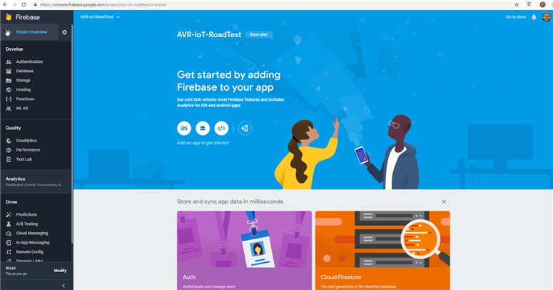
I navigated to the Firebase console and clicked on Add project
I then had a dialogue where I added my Google Cloud Project just created to Firebase.
Once I had selected to accept the terms, the Create project button changed to Add Firebase and became clickable. Once clicked, a dialogue opens to confirm the billing plan.
Once I had clicked Confirm Plan, the project was created in Firebase and the dashboard opened.
|
| Step 5 | Set Up Leverage UI in Google Cloud Account
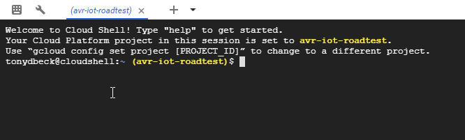
I first activated the Google Cloud Shell which gives a command line access to configure your project. I did this by clicking the CLI button in the tool bar.....
This then opens a command line shell at the bottom of the page.
This is quite a neat and powerful feature. The Cloud Shell evironment is a Docker Container that is started from a Google-maintained image. It is also possible to create your own Docker image and use that!
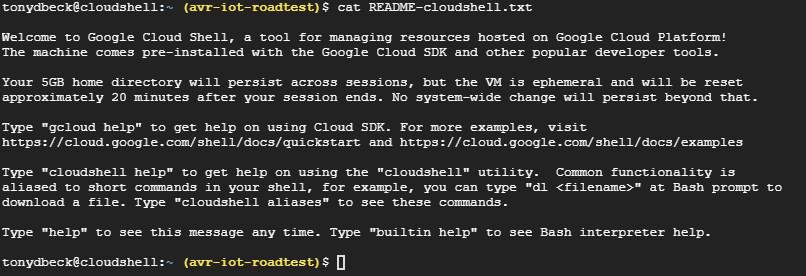
There is a README file located on the folder that contains the following:
To be able to set up the Leverage application, I first cloned the Leverege project into my shell environment by running the following command:
This command completed pretty quickly and then presented me with the following
I then copied my UID from the last part of the address in the CLICK-ME.HTM file on the board and pasted it into the shell.
I then had the option to chose my IoT Core registry name - I changed this to AVR-IOT-RoadTest
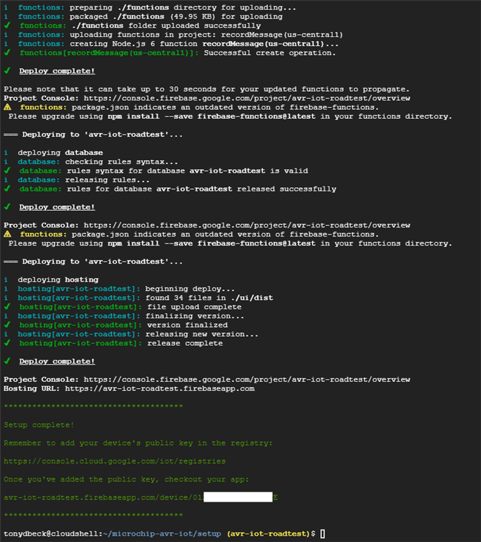
The script then ran and set everything up in the project that was required. It carries out the following tasks:
This whole task is very well automated and made the set up very easy! It took a few minutes, but does report the progress well.
Once complete I had the following in the shell:
|
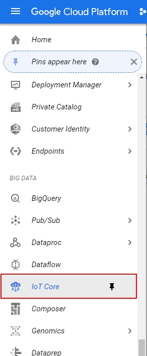
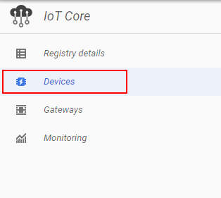
| Step 6 | Add Device Public Key to IoT Core Registry To allow my device to talk to Google Cloud, I need to add the Public Key to my account. To do this, I selected IoT Core from the Google Cloud Console Menu.
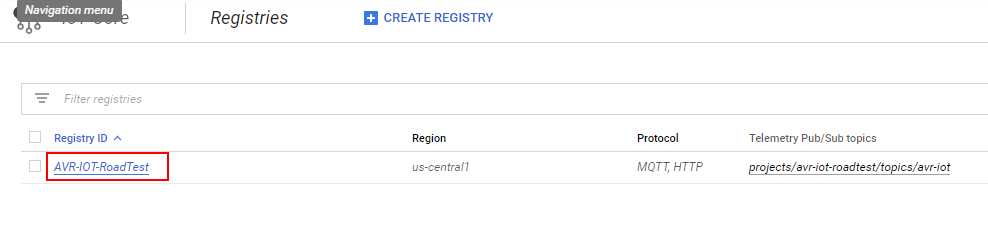
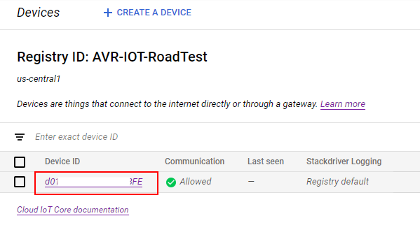
Then selected my registry that had been created.
Then selected Devices
And then selected my device that had also been created.
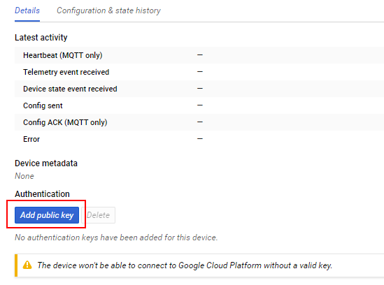
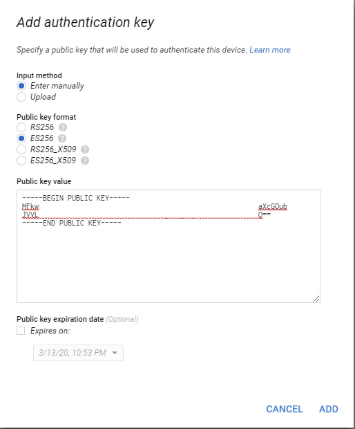
From there I could see the option to add a public key
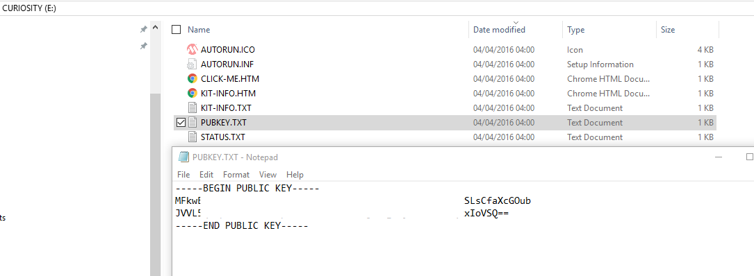
The key is contained in the PUBKEY.TXT file on the board. I simply copied the text from this and pasted it into the Add authentication key dialogue.
I had to also select ES256 as the key type as it is a key based on Elliptic Curve Cryptography.
|
| Step 7 | Modify Firmware Settings to Connect to Private Cloud In the Leverege instructions, they state to use the Atmel START web based utility, which is what I tried initially. However I am going to use the Microchip Code Configurator in this write up for 2 reasons -
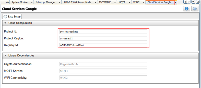
First with the MPLAB AVR-IOT project still open, I had to re-open the MCC from within MPLAB by clicking the MCC button on the toolbar.
Then, in the Cloud Services Google tab, I entered the corresponding details for my project.
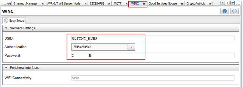
Then, in the WINC tab, I entered my WiFi details so these would be saved in the firmware.
|
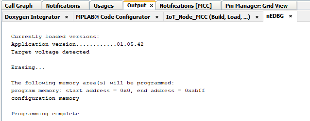
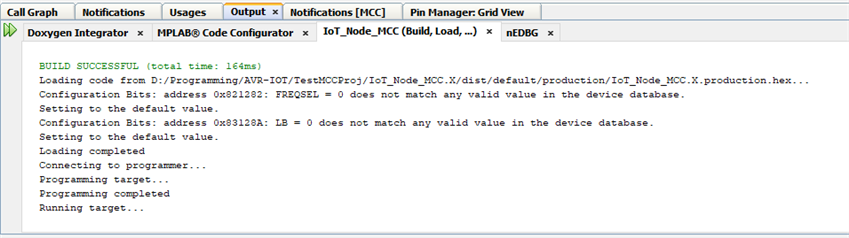
| Step 8 | Build and Load Project
Click to build and load the project.
Once loaded successfully, I saw the following in the Output and nEDBG panes:
|
| Step 9 | View Data
Finally, I navigated to the web page that was now being hosted on my private cloud. This web page takes the format: https://avr-iot-roadtest.firebaseapp.com/device/XXXXXXXXX where the XXXXXXXXX is the corresponding device ID. In this video, you can see the live data coming into my app:
In this video, you can see the data populating the database as it is being delivered:
|
My main goal for this review was to connect the board to my home heating system to send local temperature data to my system and receive information back to display on a locally connected display. I had initially thought this would be a relatively simple task but unfortunately I have not yet succeeded. I am determined to find a way and will post a subsequent blog once I have figured it out but for now, I will try to explain what have tried so far, what issues I have encountered and what I am planning on trying out to get it working
First of all, a little back ground on my Home Heating System.......
I had seen a few IoT systems on the market aimed at connecting a standard domestic heating system to the cloud, notably in the UK - the NEST and HIVE. Both of these systems are very nice, but also quite pricey. So, I decided I would have a go at developing my own system using some of the readily available cloud services to link it to the cloud.
For my system, I have uses a Raspberry Pi 3 at its core due to the low cost, power and ease of use. I have then placed a number of DS18B20 temperature sensors on my hot water tank, some of the pipes and a couple around my home, these then connect together at my Pi on a 1-wire bus and feed temperature data to the Pi.
The sensors I have used are like the following:
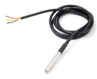
I then have Node-Red running on my Pi which handles all of the data collection, processing / control, UI via a web interface and Cloud Connectivity. I have used two cloud providers - io.adafruit.com and Blynk. Both have unique and very useful features.
The one big downside to my current set up is that the two sensors around my home are in fixed positions in the upstairs and downstairs hallways. This is where I had hoped I could use the AVR-IoT board - as a portable, wireless temperature device.
As the heart of my system is the Raspberry Pi running Node-Red, the key thing for me was to get the data from the AVR-IoT board into Node-Red. When I applied for the Road Test I had expected this task to be a very easy task - especially as this board is all set up to integrate into the Google Cloud Platform,
6.0 Demo Program Overview - AVRIoTWGSensorNode
<html><head><title>Jive SBS</title></head>
<body><font face="arial,helvetica,sans-serif">
<b>Error</b><br><font size="-1">
An general error occurred while processing your request.
</font></font></body></html>
| {tabbedtable} Tab Label | Tab Content |
|---|---|
| cli | cli Command Line Interface <html><head><title>Jive SBS</title></head> <body><font face="arial,helvetica,sans-serif"> <b>Error</b><br><font size="-1"> An general error occurred while processing your request. </font></font></body></html> |
| cloud | cloud (shows up in the second tab) <html><head><title>Jive SBS</title></head> <body><font face="arial,helvetica,sans-serif"> <b>Error</b><br><font size="-1"> An general error occurred while processing your request. </font></font></body></html> |
| Config | cloud (shows up in the second tab)
|
| credentials_storage | credentials_storage (shows up in the second tab)
|
| cryptoauthlib | cryptoauthlib (shows up in the second tab)
|
| doxygen | doxygen (shows up in the second tab)
|
| examples | examples (shows up in the second tab)
|
| include | include (shows up in the second tab)
|
| mqtt | mqtt (shows up in the second tab)
|
| src | src (shows up in the second tab)
|
| utils | utils (shows up in the second tab)
|
| winc | winc (shows up in the second tab)
|
| Top Level Application Files | Top Level Application Files (shows up in the second tab)
|
| Document Description | Link |
|---|---|
| AVR-IoT WG User Guide | http://ww1.microchip.com/downloads/en/DeviceDoc/AVR-IoT-WG-Development-Board-User-Guide-50002809B.pdf |
| AVR-IoT WG Technical Summary | http://ww1.microchip.com/downloads/en/DeviceDoc/AVR-IoT0WG-Technical-Summary-50002805A.pdf |
| ATWINC15x0 (Radio Module) Data Sheet | http://ww1.microchip.com/downloads/en/DeviceDoc/70005304B.pdf |
| ATWINC1500 (Radio Module) Software Design Guide | http://ww1.microchip.com/downloads/en/devicedoc/atmel-42420-winc1500-software-design-guide_userguide.pdf |
| Description | Link |
|---|---|
| AVR-IoT Homepage | https://www.element14.com/community/external-link.jspa?url=https%3A%2F%2Fwww.microchip.com%2Fdesign-centers%2Finternet-o… |
| Atmel START | https://www.element14.com/community/external-link.jspa?url=http%3A%2F%2Fstart.atmel.com%2F |
| Sensor Node Example Page | https://www.element14.com/community/external-link.jspa?url=https%3A%2F%2Favr-iot.com%2F |
| Google Cloud IoT Core | https://www.element14.com/community/external-link.jspa?url=https%3A%2F%2Fcloud.google.com%2Fiot-core%2F |
| Getting started with the AVR-IoT | https://www.leverege.com/blogpost/avr-iot-guide-pushing-data-to-cloud |
| Example app GitHub page | https://www.element14.com/community/external-link.jspa?url=https%3A%2F%2Fgithub.com%2FLeverege%2Fmicrochip-avr-iot |
| ATWINC1500 Homepage | https://www.microchip.com/wwwproducts/en/ATWINC1500 |
| AVR-IoT Board Firmware - Microchip GitHub | https://github.com/MicrochipTech/AVR-IoT_WG_Sensor_Node |