RoadTest: Maxim Integrated MAX31343SHLD# Real Time Clock
Author: fmilburn
Creation date:
Evaluation Type: Semiconductors
Did you receive all parts the manufacturer stated would be included in the package?: True
What other parts do you consider comparable to this product?: A comparison will be made with the DS1307 and DS3231, two other I2C Real Time Clocks by Maxim.
What were the biggest problems encountered?: No substantial problems.
Detailed Review:
by Frank Milburn
Introduction
The objective of this RoadTest was to describe and test some of the capabilities of the MAX31343 Real Time Clock and the MAX31343SHLD# which Maxim Integrated provides to evaluate it.
The Maxim Integrated MAX31343SHLD#MAX31343SHLD# is an Arduino factor shield used to evaluate the MAX31343MAX31343 Real Time Clock (RTC). The MAX31343 is a low power temperature compensated RTC which does not need an external crystal. Communication with the IC is over I2C and time keeping accuracy is given as +/-5ppm (+/-0.432 seconds/day) over a range of -40C to +85C. The change due aging in the internal oscillator is stated to be less than +/-1ppm for one year and less than +/-2ppm for up to 10 years. The RTC provides seconds, minutes, hours, day, date, month, year, and century information as well as two alarms and square wave output.
The RoadTest evaluation consisted of the following:
Unboxing
The MAX31343SHLD# arrived unharmed packaged in a plain cardboard box that had been placed in in a second box for shipping. Inside was the RTC shield in antistatic packaging along with the micro USB cable.
| {gallery} Unboxing |
|---|
Box |
Box Opened |
Top |
Bottom |
The shield has the Arduino Uno form factor but also has a MAX32625MAX32625 PICO Arm Cortex-M4 Microcontroller with 512kB Flash and 160kB SRAM pre-programmed to work with the GUI for assessing the RTC. The microcontroller is visible on the left side on top of the shield.
The board was put together for experimentation and there are plenty of jumpers and test points on the top. The part labelled U1 is the MAX31343EKA+ RTC. The parts labelled U6, U7, and U8 are MAX14689AETB+MAX14689AETB+ DPDT switches used for switching between components on the board and the three small 8 pin parts are level translators. The unpopulated footprint labelled U2 is for the TDFN package version of the MAX32625 RTC. Provision is made for various means to power the RTC, including a super capacitor. An actual implementation can be much simpler of course and that will be examined.
Overall quality was fine with only a small spattering of solder of no consequence on the bottom of the board between the QR scan code and the header for the MAX32625 PICO. The pins for attaching to an Arduino are spindly and since placed on the bottom of the PCB could short on a conductive surface. I'm not a fan of this form factor but understand choosing it due to the ubiquitous nature of the Uno. Provision of C/C++ code to work with an Arduino is a plus and will be examined later in the RoadTest.
MAX31343 IC Overview
A simplified block diagram for the MAX31343 is given below.
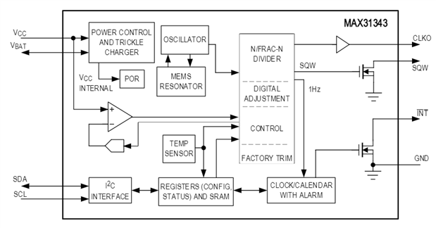
Credit: MAX31343 Datasheet
The high level specifications are:
| Interface | I2C |
| VSUPPLY (V) | 1.6 to 5.5 |
| Date/ Time Format (hh = sec/100) | YY-MM-DD/ HH:MM:SS YY-MM-DD/ HH:MM:SS:hh YYYY-MM-DD/ HH:MM:SS |
| Time Keeping Current (nA) (typ) | 940 |
| Memory Type | NV SRAM |
| Memory Size (Bytes) | 64 |
| Time of Day Alarms | 2 |
| Integrated Resonator | MEMs |
| Package/Pins | COW/8 TDFN/8 |
Credit: MAX32625 Product Details
A typical application circuit looks like this:

Credit: MAX31343 Datasheet
The MAX31343 package is a custom pitch WLP.
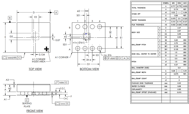
Credit: Maxim Integrated Package Drawings
High Level Specification Comparison
The MAX31343 was compared to two other Real Time Clocks that I have some familiarity with and are shown in the table below.
| MAX31343EKA+ | DS3231 | DS1307 | |
|---|---|---|---|
| Communication | I2C | I2C | I2C |
| DC Current Consumption | 940nA (typical) at 3V3 | 200uA(max) at 3.63V | 100uA at 5V ? |
| Accuracy -40°C to 85°C | +/-5ppm | +/- 3.5ppm | Dependent on XTAL |
| Package | WLP | SOIC-16 | SOIC-8 |
| Cost US Dollars (Newark) for 100 | $2.63 | $7.30 | $2.25 (without XTAL) |
The Maxim MAX31343 being tested here has a built-in MEMS oscillator with +/-5ppm accuracy, temperature compensation, and less than +/-2ppm drift over 10 years. The MAX31343 can operate between 1V8 and 5V and provides for battery or supercapacitor backup. Package size is smaller than the other Real Time Clocks in this comparison with minimal passives and no XTAL.
The Maxim Integrated DS3231 DS3231 can operate from 2V3 to 5V5 and is more accurate than the MAX31343 but uses more power and is considerably more expensive. It comes in a larger package.
The Maxim Integrated DS1307DS1307 accuracy is dependent on an external crystal with accompanying initial crystal trimming plus temperature and time drift. The DS1307 comes in a larger package, is limited to 5V operation and the footprint and cost of a crystal must be added.
Cost for the MAX31343EKA chip is $2.63 for 100 at Newark Vs. $2.25 for the DS1307 in quantities of 100 (excludes crystal) and $7.30 for the DS3231. Maxim mentions a price of $1.75 per chip in quantities of 1000 in a marketing video for the MAX31343. The price of the MAX31343SHLD# is $122.88.
Summary: The MAX31343 seems reasonably priced and the small form factor with +/-5ppm accuracy makes it attractive.
Testing
Equipment used in this RoadTest for testing includes:
GUI Overview
The GUI was downloaded from the Maxim Integrated site after setting up a user account. The installer download was initially blocked by Microsoft Defender with the following message which occurs when the MSI is not signed:

The software installer was reported as reputable to Microsoft but it was necessary to temporarily reduce the security features to allow it download. From that point on no issues were encountered with installation.
After connecting the shield to the PC and starting the MAX31343SHLD software a small splash screen followed by the GUI appears with the Configuration & Time tab visible and showing that the MAX31343 was detected. There are four tabs in total as seen in the screenshot below.

Summary: Installation was relatively straightforward but it would have been nice for the Windows installation to be signed and recognized by Windows Defender.
Configuring Time
Setting the time is quite simple under the Configuration & Time tab and uses the pull-down menus followed by the Set button. The status log reports the status of the writes to the RTC registers. The places where changes have been made to set the time are circled in red.

There are a number of other configuration settings which for the most part are self explanatory but several are delved into more deeply below. Since the status log reports the registers being written to when configurations are changed the datasheet can be cross referenced for documentation on that register.
Summary: Setting time and configuring the main parameters of the RTC is straight forward and simple with the GUI. The status log gives useful information on the registers and changes are made.
Configuring Alarms
Alarms are easily set in the GUI after selecting the Alarms & Timer tab. There are two alarms available and several options for alarming which are accessed from the Repetition Rate pull-down. The following tables taken from the datasheet show the different ways alarm timing can be set.

Credit: MAX32625 Datasheet
In the following screenshot Alarm 1 has been set to go off when there is a match of minutes and seconds (26:00). Interrupts for Alarm 1 have been enabled. The places where changes have been made are circled in red.

At 19:26:00 an interrupt occurs as shown in the screenshot below. The small red arrow was added to show where the interrupt is indicated to the user.

Summary: Configuring the two alarms is easy with the GUI. A number of useful options and interrupt setting are available.
Configuring Timer
The Timer Configuration group located under the Alarms & Timer tab provides access to a countdown timer with a pause function. The frequency can be set to 1024Hz, 256Hz, 64Hz, or 16Hz and the timer initiated anywhere from 255 to 0 counts. The timer can also be paused at any point and caused to repeat over and over. The timer can be set to cause an interrupt in the Interrupts group.
In the test below the timer is enabled, repeating, has a frequency of 16Hz, and was initially set to start at 16. The timer interrupt and flag was also set and the INT box is green showing the interrupt occurred as expected.

Summary: The timer was tested and worked as expected.
Determining Clock Accuracy
My initial approach was to compare time given by the MAX31343 to that of my Windows computer using NTP servers to assure accurate PC time. In theory this could allow accuracy to better than 100ms on the PC as described here. In reality I'm pretty sure that is not the case as the was set time manually and observations made by eye. What may be a better method is to use GPS and a microcontroller as suggested below. To synchronize the real time monitoring check box was set to Continuous Read and manually synched with the PC clock over the internet. The MAX31343 was powered over USB from the PC and Vcc set to 3V3. The ambient temperature is a bit over 20°C.
The test was done over a 5 day period and although the MAX31343 is advertised to give +/- 5ppm accuracy we expect it may do better than that based on the datasheet when ran at ~20°C and 3V3.

Credit: MAX32625 Datasheet
The initial synchronization error by was observed to be less than a half second and the difference was then checked daily. In order to get the best accuracy from the PC it was synched to get a fresh reading off the internet before taking a new reading.
| Date | MAX31343 (hh:mm:ss) | PC (hh:mm:ss) | Difference (seconds) |
|---|---|---|---|
| May 04, 2021 | 21:11:39 | 21:11:39 | ~0 |
| May 05, 2021 | 21:10:09 | 21:10:09 | ~0 |
| May 06, 2021 | 22:07:24 | 22:07:24 | ~0 |
| May 07, 2021 | 18:49:52 | 18:49:52 | ~0, MAX31343 somewhat ahead by eye |
| May 08, 2021 | 22:51:53 | 22:51:53 | ~0.5, MAX31343 ahead by eye |
| May 09, 2021 | 21:01:05 | 21:01:05 | ~0.5, MAX31343 ahead by eye |
This was not a high stress test in that it was of limited duration, was done in a benign environment with relatively stable voltage supply and temperatures in the range of 20°C to 25°C. After 3 days a slightly faster MAX31343 was perceived but less than 1/2 second. By 4 days the MAX31343 was maybe a half second ahead. On the fifth day the difference was visually about the same as day 4. The testing procedure is suspect however due to latency when synching the PC to NTP servers and human observation by eye.
A better way to test might be to use the Arduino code outlined below along with a GPS to set the time on the MAX31343. The time from the MAX31343 could then be compared by the Arduino to the GPS at intervals for a more accurate test and run over a longer time period.
Summary: The test procedure was crude but the results indicate the part was operating within specification under the conditions tested. A better test procedure done over a longer time with temperature and voltage supply variation would be required to fully verify the datasheet.
Power Consumption / Current Draw
The current draw while the MAX31343 was in timekeeping mode was measured using a digital multimeter capable of measuring into the nanoamps. The expected current draw for the MAX31343 at room temperature when measuring time at 1 Hz and output set to 3V3 is approximately 940nA as shown in the following figure.

Credit: MAX32625 Datasheet
The procedure used was:
The measured current on the meter was not steady but for the most part was between 740nA to 980nA with a maximum of 1200nA. The average was 800nA. Due to the coarseness of my measurements I consider this test indicative of the very low current requirements and have no reason to doubt the datasheet. A comparison between the datasheet and the measurements made is shown tabulated below.
| Typical | Maximum | |
|---|---|---|
| Measured | 800nA (Varied mostly in range 740nA to 980nA) | 1200nA |
| MAX31343 Datasheet | 940nA | 1500nA |
Summary: The test equipment used was of low resolution but confirmed the low power requirements of the MAX31343 IC and I have no reason to doubt the specifications supplied in the datasheet. A more accurate ammeter and varied temperature and supply voltage is required to fully verify the datasheet.
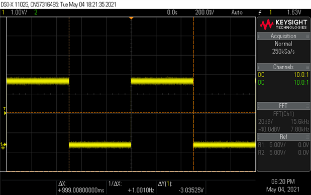
Square Wave
The RTC has a 1Hz temperature compensated square which is shown in the screenshot from my oscilloscope below: Accuracy is 1ppm/V according to the datasheet.

Summary: The oscilloscope shows 1Hz as expected.
CLKOUT
The datasheet states the CLKO pin is an uncompensated output with +/- 1% accuracy. Output frequency can be 32.875kHz or 1Hz - 128Hz by factors of two. The output is CMOS Push-Pull with a 50% Duty Cycle. The clock output can be enabled in the RTC Configuration box and J1 used to measure the output.
The 32.875kHz as measured on a Keysight DSOX1102G oscilloscope is shown below (32.798kHz with some variation observed).

The 1Hz output is shown below (1.001Hz measured, little variability).
Summary: The CLKO pin gives uncompensated output which may be useful for some applications. Brief tests showed it to be within the +/- 1% accuracy given in the datasheet.
Voltage Threshold and Power Mode Configuration
The MAX31343SHLD# can be set to supply power from an onboard Super Cap or external battery upon power failure. The jumper settings on JU2 are changed according to the diagram shown below:

Credit: Maxim MAX31343SHLD# User Manual
The tests for external battery backup were performed as follows:
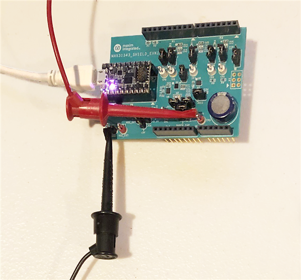
The Shield is shown below setup for the battery backup test with power coming in through the mini-grabbers.
The experiment were run several times and the MAX31343 maintained time without issue on the power supply simulating a battery.
The test was repeated but by charging up the super capacitor with the power supply to 3V (rated at 5V5) and changing the jumpers to back up from the super capacitor. Note that the MAX31343 has a trickle charger that can be used instead of a power supply to charge the super capacitor or a battery but this was not tested.
The MAX31343 was run for 1 hour on the super capacitor backup and maintained time with the voltage falling from 3.018V to only 2.969V.
Summary: The battery and super capacitor backup tests for lost power performed as expected.
Registers
The Registers tab gives access to all the registers. To read, select the desired checkboxes and click Read.
Registers can also be written to by entering an 8 bit value as hexadecimal and clicking Write (deselect all register that you don't want to write to first) as shown below. The Status Log reports the results.

Summary: Reading and writing to registers is easy and useful.
RAM
The GUI also gives full read and access to RAM on the device.

The MAX31343 has a data retention mode shuts down the functional blocks (including the oscillator) except for I2C. In this mode it consumes 100nA according to the datasheet and retains all the register and RAM contents. Reading and writing to RAM was successfully observed.
Summary: The data retention mode was not explored further than to review the datasheet and observe that the feature functions.
Arduino Code
Maxim provides an Arduino Library for the MAX31343 with examples for the Alarm and Timer. The MAX31343SHLD# has the Arduino Uno form factor and that is what it was tested with. There is not a lot of direction on using the shield with an Arduino but I removed the MAX32625 PICO development board from the shield and plugged the Arduino Uno into the bottom. The male pins on the shield are somewhat longer than needed and spindly - they had to be straightened and coaxed a bit into the Arduino Uno. It was not necessary to move the jumper connections from the default positions.

The MAX31343_Alarm.ino example provided in the library demonstrates the time of day alarm feature with interrupts. Alarm1 is set to interrupt when date, hour, minute and seconds match. Alarm2 is set for date, hour, and minute matching. The output worked as expected for the example code and the setup and screen are shown below.

The second example provided with the library demonstrates use of the timer with interrupts. The screenshot below shows the output.

The Arduino code examples ran without issue which is the way we like it. The library C++ code looked well structured and complete so it shouldn't be too hard to port since this has an I2C interface. It compiled within the Arduino IDE for the Adafruit QtPy M0+ development board so it didn't appear to have AVR specific code in it but I didn't try running the shield from the QtPy.
Summary: The Arduino examples provided by Maxim ran without issue and provide well structured code for porting to other microcontrollers.
Future Plans
All of the tests outlined in my submission for this RoadTest were successfully completed. As a future project I considered designing a simple PCB breakout board for the MAX31343 as a self learning exercise on use of BGA parts. There are a minimal number of passives but the WLP pitch is 0.5mm with 8 balls on the IC. In the end discretion got the better part of valor and I've shelved that project for the time being.
I intend to continue measuring clock accuracy in the coming weeks.
Summary and Conclusions
Thank you to Maxim Integrated and element14 for providing the MAX31343SHLD# and the MAX31343 Real Time Clock for testing. All the testing that was planned and submitted in my RoadTest application were carried out successfully and without major issues. The MAX31343 met the datasheet specifications within the ability of the test procedures used to measure them. Just as important, the GUI and MAX31343SHLD# provide the means for doing more precise testing and further testing for temperature and voltage supply influence.
The features on the MAX31343 RTC include:
In my scoring system a 9 represents high as quality expected from a major manufacturer and a 10 represents exceptional quality. I felt the GUI was exceptional and met all my needs. The Arduino code should be easily ported to other microcontrollers. Everything was easy to use once installed. The shield might seem expensive at $122.88 USD compared to the inexpensive mass produced breakout boards available for some RTC chips but those lack the testing capabilities of the MAX31343SHLD#. Thanks for reading and comments and suggestions are always appreciated.


Top Comments
Update: I continued checking accuracy daily for another 3 weeks using the procedure outlined in the Roadtest. The maximum difference from received NTP time was less than a second after a month which is…