RoadTest: Digilent OpenLogger Kit
Author: fmilburn
Creation date:
Evaluation Type: Test Equipment
Did you receive all parts the manufacturer stated would be included in the package?: True
What other parts do you consider comparable to this product?: A high level comparison was made to the Pico data loggers in the RoadTest. Brief mention is also made to microcontroller based solutions.
What were the biggest problems encountered?: Not all features in the marketing material were supported by the software. Bugs were encountered in the software.
Detailed Review:
Introduction
Thank you to element14 and Digilent for the opportunity to review the OpenLogger. The RoadTest contents are as follows:
A brief summary of positive findings and problems encountered is given after the review of each feature. The demonstration project utilizes 5 channels of the OpenLogger to record light levels using photo resistors.
Unboxing
The instrument came well packaged and undamaged in a plastic bag surround by packing material inside a Newark corrugated box.
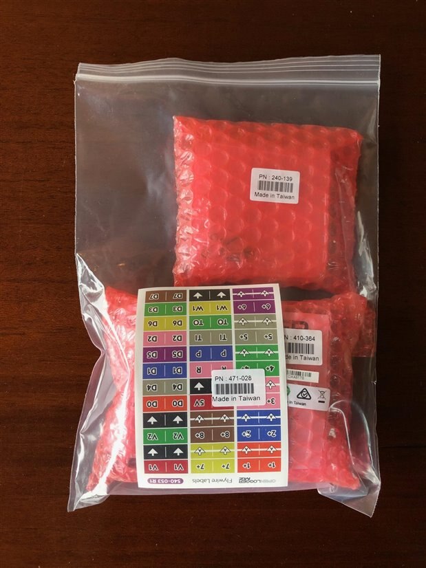
The parts are spread out below:

The package included:
UPDATE: Element14 sent me a package with the screw terminal adapter a few days after starting this review. Thank you! The screw terminal adapter is a worthwhile option in my opinion.
Overview of OpenLogger
The OpenLogger was originally a stretch goal of the OpenScope Kickstarter project. It evolved into a separate project according to this Digilent blog post and the OpenLogger Kickstarter was funded in January 2019.
Digilent made an OpenLogger new product announcement on their blog April 11, 2019. The most recent firmware on Github is Version 1.2.0 dated May 30, 2019. However, the latest version loaded by the Digilent Agent is Version 1.3.0 so Github does not appear to have been updated. Waveforms Live was last updated November 2019 as documented here. The changes were Cloud logging, log on boot, save console logging behavior between uses, bug fixes, and some changes that appear minor. The log on boot was an important addition for data logging for my use.
The OpenLogger is based on the PIC32MZ with separate ADC and DAC. The ADC is an ADS8332IBRGE. The DAC is a resistance ladder with Microchip MCP6H91-E/SN Op Amp. The WiFi is an ATWINC1500-MR210PB1952. A schematic is available here. The annotated overview below of the instrument was taken from the Digilent website.
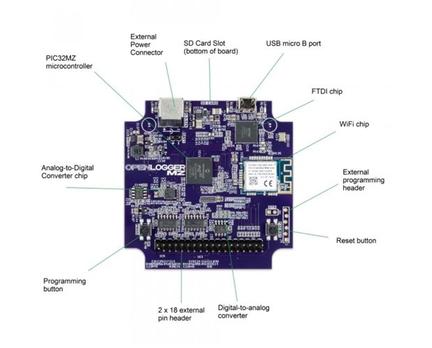
The OpenLogger hardware and firmware are marketed as being open source.
Market Comparison
Pico also makes data loggers and a comparison to the Digilent OpenLogger is shown in the table below (click to enlarge).
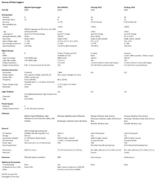
The Digilent OpenLogger compares well feature and price wise but software performance is a determining factor for this type instrument. Since the Pico instruments were not evaluated and a software comparison made the relative value was not determined.
Another option might be microcontroller based daughter boards like the Adafruit Data Logging shield for Arduino which while having resolution and voltage limitations does have a real time clock.
Getting Started with OpenLogger
NOTE: OpenLogger can only be used in a Windows environment but the forum states it can be used on a Mac running Windows.
A small sheet of paper packaged with the kit that gives a link to the instructions and training material. The user interface is through WaveForms Live (waveformslive.com) a browser based interface. Before Waveforms Live is used it is necessary to install the Digilent Agent for updating the firmware and getting started. Installation of Digilent Agent went without issue on a Windows 10 machine and directions were easy to follow.
The first time the Digilent Agent interface is opened it is necessary to ADD A DEVICE and connect via the AGENT over USB to the OpenLogger. A firmware update to the OpenLogger must be made before it can be used. The most recent version is 1.3.0 which was installed without incident. As noted above, the most recent version in Github was version 1.2.0 at the time this was written. WaveForms Live can then be opened.
Upon opening WaveForms Live a calibration is done by following the instructions provided. This went without incident. Only the 8 analog channels require calibration and the parameters are stored for future use and available on startup of the instrument. Recalibration is easily done if needed. The OpenLogger Pinout shown below is available on their website as well as in the software and shows the 8 pins which must be calibrated in the top row, left.
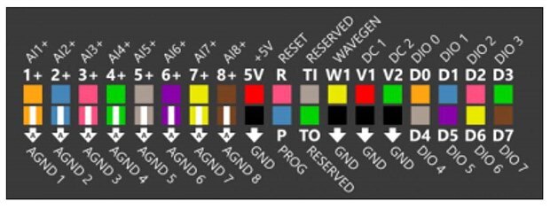
After that the instrument is ready to use when the Agent is launched and WaveForms Live is in the browser.
RECOMMENDATION: Install the case before calibration which I did not do. The flying leads must be removed before the case is assembled and the connection to the flying leads was quite tight. The PCB was flexing even though the leads were removed slowly and evenly. No damage was done but still removal and replacement should probably be minimized.
The case is fiddly to assemble but the instructions are clear and it went together without incident.

The tags for the leads took a while to attach and though taking care not to place them wrong I still put one in the wrong place. Pulling the adhesive apart is impossible so I ended up cutting it and then reattaching it in the correct place with sticky tape.
UPDATE: As noted above Element14 sent me the screw terminal adapter a few days after I started the review. Again, the flying leads had to be removed which flexes the PCB but the screw terminal adapter installed easily and neatly as seen in the photo below.

Summary:
Overall the boards appear well made and are neatly laid out. No issues were encountered other than the difficulty of removing the flying leads and the fiddly case assembly.
Feature Review
The tutorials were followed in order and observations are documented here to demonstrate how the instrument works and the available features. The tutorials are professionally done and of high quality. The videos were developed for the Digilent OpenScope but for the most part the OpenLogger works the same since the WaveForms Live interface is being used.
A Keysight DSO1102G oscilloscope and an Extech EX330 Multimeter were used as a comparison check for output and recorded values on the OpenLogger.
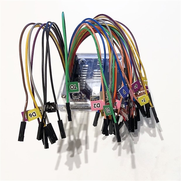
Before going further, a word about the flying leads. The leads are handy for breadboard activities and students but more robust connections are desirable for many activities and a daughter board with screw type connectors is available. Below is a representative setup using a breadboard and the flying leads. I find the flying leads difficult to sort through and prefer the connections made by screw terminals. Fortunately Element14 provided a screw terminal adapter which arrived after the RoadTest began but in time for most of the testing.

Function Generator
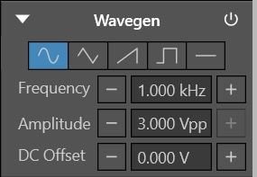
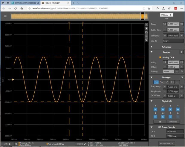
The waveform generator (and a number of the other features) cannot be adjusted on the fly. It is necessary to stop streaming / datalogging before making changes. The waveforms available are sine, triangle, sawtooth, square, and DC. Frequency, amplitude and DC Offset can all be adjusted. A control panel screen shot is shown below.
After starting up the Wavegen at the default setting in the panel above a clean signal is seen. But immediately upon starting streaming of the OpenLogger inside Waveforms Live a glitch occured which can be seen in the screenshot below from Waveforms Live.

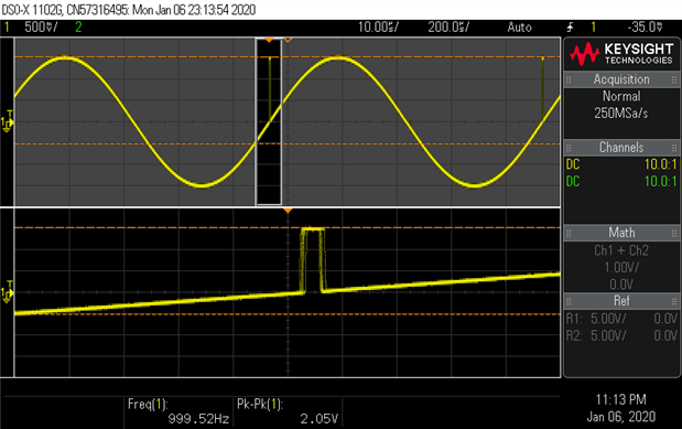
The glitch was observed only on the first attempt after start-up and disappeared when the Wavegen and Streaming were turned off and then on again. It was reproducible whenever the OpenLogger and Waveforms Live were started anew (but again disappeared when Wavegen and Streaming were restarted). The screenshot below from the Keysight oscilloscope shows the glitch zoomed in.
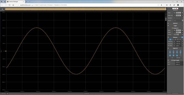
If the Wavegen is turned off and then restarted inside the same session the glitch disappears as shown on Waveforms Live below.
Most of the time things behaved more or less as expected although there was lag noted in the controls. The browser interface is not overly responsive. This behavior is shown in the videos below. There were also times where things froze completely and the browser needed to be restarted.
The Wavegen output from OpenLogger and the resulting input viewed with Waveforms Live Streaming were tested at 10 Hz, 1 kHz, 10 kHz, and 50 kHz. 50 kHz being the stated bandwidth at -3dB.
Below are all of the 10 Hz waveforms.
| {gallery} My Gallery Title |
|---|
10 Hz Sine
|
10 Hz Sawtooth
|
10 Hz Square
|
10 Hz Triangle
|
The waveforms at 10 Hz all looked OK on the oscilloscope. In a similar manner, the 1 kHz and 10 kHz signals looked OK.
This is what the 50 kHz sine wave generated by OpenLogger looks like in WaveForms Live.

The same 50 kHz sine wave generated by OpenLogger is shown below on the Keysight oscilloscope for comparison.
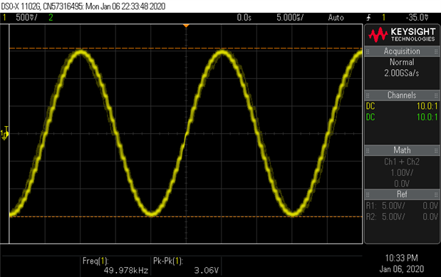
Capture detail is much reduced on the OpenLogger and adding channels further reduces the ability to capture high frequency waveforms proportionally. The Keysight oscilloscope shows some stair stepping in the 50 kHz signal generated by the OpenLogger Wavegen.
A quick look at the various outputs from the OpenLogger was done using FFT on the DSOX1102G oscilloscope. The screenshot below is a 2 Vp-p 10 kHz sine wave which compared favorably with the output from the Keysight DSOX1102G waveform generator.

The cursor was purposely manually set slightly off the peak frequency in the screenshot above so the peak could be seen. The actual frequency is very close to the 10 kHz set in the OpenLogger.
Summary:
The display is large and easy to read. Measurements of the output voltage, frequency, and waves compared well with the oscilloscope for this type instrument and would be suitable for educational use.
There is a bug in the waveform generator / streaming when it is first turned on which causes a glitch. It was reported 7 Jan 2020 to the Digilent user forum. It was acknowledged quickly by the forum moderator and I am awaiting response. Input to Waveforms Live is useable but not overly responsive and can lock up at times or at least become completely unresponsive for practical purposes. Some of these issues are demonstrated in the videos below.
Data Logging
Data can be logged to an SD card and/or streamed to WaveForms Live. There was a November 2019 update to the software which allows uploads to Mathworks ThingSpeak Cloud which was not tested. A 32 GB Lexar “HIGH-PERFORMANCE” 633x microSDHC UHS-I card was used in the done tests here and no problems were encountered with the card. According to forum comments the largest card that can be handled is 32 GB and it should be a “high speed camera” card.
The data logging entry panel is shown below:

The time scale is for viewing on the chart. The important parameters are:
As noted above, data files can be huge if defaults are not changed. There is a setting in the Advanced menu which can be used to select a finite number of samples and this might be useful at times but as will be noted below the minimum sample rate from the datasheet is 50 samples / second.
There is not a real time clock and the data is not time stamped.
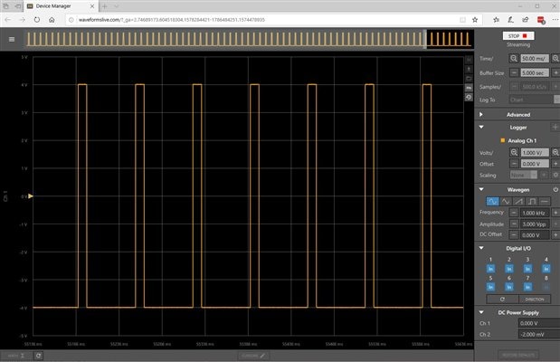
The test setup for datalogging is shown below and used the screw terminal adapter. The Keysight DSOX1102G was used to generate a 10 ms pulse from -4 V to +4V which is displayed on Waveforms Live and on the oscilloscope.

In the photo above the pulse is being fed to two channels of the OpenLogger. In the screenshot below Waveforms Live is displaying a single channel.
During datalogging output to the SD card is made in a binary compressed format that cannot be read directly in other applications such as a spreadsheet. There was not a converter when the firmware / software was first released but subsequently an executable that can be run from the command line was released which will convert the binary file to a comma separated value (CSV) file. The conversion instructions are described here.
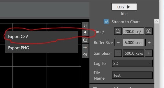
It is also possible to directly export CSV files from Waveforms Live using the button circled below and the flyout input panel although I did not see it mentioned in the tutorials.
On the first attempt to log data the default values in the data logging entry form were used and logging left running for quite some time (minutes). This resulted in a binary log file of size 434 MB. When the converter was run it grabbed 15.9 GB of memory on a 16 GB memory machine and took a very long time to convert (on a very fast machine). The resulting csv file was 3.2 GB. This made the data difficult to analyze so pay attention to the samples / second when setting up to log data.
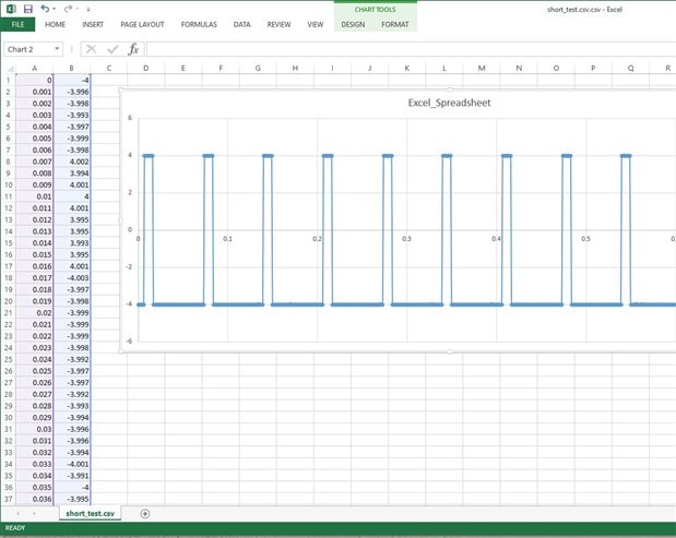
The input panel settings were then changed to 1000 samples / second and saved into a new file called Short_Test for 5 seconds. The resulting file was 14 KB (much more reasonable) and the csv file was 87 KB. The csv file was opened up in Excel without issue and plotted to demonstrate the integrity of the data.
Summary: The data is not timestamped which would be nice and imperative in some applications. Data can be captured on a SD card, moved to the computer, and converted for use via a command line executable. Data conversion for large files is not efficient for very large files but does work.
Digital I/O
The marketing material says this (yellow highlight added) about digital I/O:
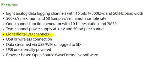
The training material says this:

Since the control panel does have the digital I/O panel I tried it anyway and found that it is not implemented.
Summary: While the marketing data states that there are eight digital I/O channels, the instructional material states that it has not been implemented in software and a test showed it not to be there as well.
DC Power Supply
The OpenLogger has two DC power supplies that can provide plus or minus 4V and up to 50 mA per channel. The input panel is shown below.
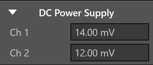
Input is done by typing in the desired value. After input the panel reads back the value – in the default case above values of 0 V were entered for both channels and the measured output is displayed as 14 and 12 mV.
Limited testing was done. The values for each channel were set as shown in the table below and checked with an Extech EX330 multimeter. All values in Volts.
Channel 1 Set | Channel 1 Display | Channel 1 Extech | Channel 2 Set | Channel 2 Display | Channel 2 Extech |
|---|---|---|---|---|---|
-4 | -3.969 | -3.951 | -4 | -3.966 | -3.963 |
-3 | -2.971 | -2.960 | -3 | -2.971 | -2.968 |
-2 | -1.977 | -1.969 | -2 | -1.979 | -1.975 |
-1 | -0.980 | -0.979 | -1 | -0.982 | -0.982 |
| 0 | 0.014 | 0.010 | 0 | 0.012 | 0.009 |
| 1 | 1.009 | 1.000 | 1 | 1.011 | 1.002 |
| 2 | 2.006 | 1.990 | 2 | 2.001 | 1.994 |
| 3 | 2.998 | 2.980 | 3 | 2.993 | 2.987 |
| 4 | 3.995 | 3.971 | 4 | 3.998 | 3.980 |
A screenshot from the Keysight DSOX1102G showing output noise with Channel 1 set at 4 V with a 100 ohm resistive load (40 mA being delivered) is shown below. The major vertical divisions are 5 mV and time base is 20 ms / division.

Summary: The DC power supplies were not tested extensively but look acceptable for an instrument of this type and where no more than 50 mA at plus or minus 4 V is required. It is nice that there are two channels. Current is not displayed and there is no current limiting. As will be seen later, the DC power supply does is not remembered when logging from boot up and thus is not available. This would seem to be an omission that could be added in a future software / firmware update.
Math and Cursors
The OpenLogger is capable of setting cursors and providing some additional information on a waveform called math. The input panel for cursors is located at the bottom center of the WaveForms Live window and looks like this:
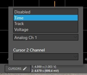
Cursors can be set for time, “track”, or voltage and can be moved about with the mouse. These settings are rudimentary but work well enough. It is not possible to independently move both time and voltage settings.
The math input panel is shown below and is located at bottom left of the WaveForms Live window.

These are not the traditional math function of an oscilloscope but rather various measurements taken from the waveform / trace. If selected, the measurement is shown at the bottom of the Waveforms Live Window. Unfortunately the software has a bug and can produce erroneous results as described below.
The following is a screenshot from the Keysight DSOX1102G which is producing a 100 Hz, 2 Vp-p sine wave to be read by the OpenLogger.

And here is a screenshot from the OpenLogger that shows the problem:

It is hard to read but the frequency is shown to be 250 Hz when it is actually 100 Hz as demonstrated by the oscilloscope and by counting time divisions in Waveforms Live. There is a forum entry posted July 2019 on the Digilent site explaining the problem.
If insufficient time is given for the math function to process the buffer, which is more likely with a large buffer, then erroneous results can occur. Unfortunately the errors are posted without warning that the calculation was not completed. It is possible to get accurate answers by using a smaller buffer or by stopping streaming early as shown below:
Summary:
The cursors are rudimentary but work. There is a bug associated with math that allows it to make erroneous reports without warning to the user which will be demonstrated in one of the videos that follows. The math functions are actually measurements of frequency, amplitude, voltage, etc. If the sample size is small enough and sufficient time is given then the math function gives correct output. Math function output should disappear along with the cursors when streaming is started up again.
While not demonstrated here there is a scaling feature in the channels menu that allows simple multiplication by a factor which is useful for say using Ohm’s Law to convert voltage to current across a known resistor. This was tested and works.
WiFi
The OpenLogger had more difficulty obtaining a reliable WiFi connection in my lab (which is located some ways from the network connection) than other devices I commonly use there. By placing the OpenLogger closer to the router a reliable connection was obtained. There is a WaveForms Live app for Apple devices that was successfully added to an iPhone and an iPad. However, WaveForms Live would not open up and show the OpenLogger in either device and gave the message "No Response Received". Perhaps it is for the OpenScope and was not implemented for the OpenLogger.
It was possible however to connect to the OpenLogger through an iPhone and iPad using a browser and advice from the Digilent forum. The WiFi connection was set up over a PC and the IP address recorded. The screenshot below is from an iPad displaying the first channel from the Demonstration Project which will be described shortly.
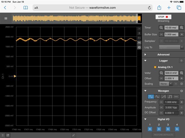
My experience was that the sample rate needed to be quite low in order to keep from losing data and the connection dropping out and similar issues are reported on the forum. The example above is at 60 kS/s. Controls were not reliable and this method is not recommend for anything other than monitoring output at the lowest rates with a tablet. Control is best done using a USB connection.
Summary:
It is possible to observe data from the OpenLogger using WiFi but only at low sample rates using a browser connection. The connection was easily dropped. The controls were not useable with a tablet and it is recommended that be done over USB.
Demonstration Project
My original project ideas for the OpenLogger were modified to better demonstrate capabilities after having used it a while. The revised test used photo diodes to demonstrate multi-channel capability away from the WaveForms Live environment.
Datalogging Photo Resistors
An experiment using photo resistors was set up on a breadboard as shown below:

In the video below basic usage is demonstrated and several bugs pointed out in the software. Apologies for the poor video quality.
Portable Logging
Additional testing was carried out to test automatic logging to the SD card when booting without WaveForms Live. The SD card was removed from the OpenLogger when logging was complete and the binary formatted data converted to CSV format so that it could be read into a spreadsheet as described above. Care must be taken to push the "prog" button (which is somewhat concealed by the screw terminal adapter) before removing power from the OpenLogger so as to properly close the Log file.
To log data to the SD card upon booting up the “Log To” set to SD and Samples/ set to the desired values in the menu as seen below (note that a user range input mistake is made and not flagged by the software).

The OpenLogger does not remember the DC power settings upon booting up and no power is supplied. Accordingly setup was changed to allow power from elsewhere for the photo resistors - in this case two “C” cell batteries were used to provide roughly 3 V. The results from the first test appeared to be in error with the time base being off. Experimenting a bit showed that the OpenLogger will not record samples at rates as low as 1.000 S/s even though the input panel allows it without warning. After hunting around the following statement was found in the Features section of the marketing material (yellow emphasis added) although it may be elsewhere in the documentation as well.

This is a "feature bug" in that it is more of a shortcoming than a feature. Something greater than 50 samples per second (rather than the 50 Samples/s minimum given above) was required in my tests as shown in the following video.
Ideally the OpenLogger would have a Real Time Clock with battery backup and allow recording data in periods of seconds and minutes or even fixed times and dates. As it is, having to record data at 100 samples per second or so with no time stamp can result in very large datasets if tests were to go on for hours or days.
The photo below shows the OpenLogger set up in a window with 5 photo resistors being recorded. The OpenLogger boots when powered from the USB supply on the far left and starts recording data.

Eventually everything worked and about an hour of data was recorded at 100 samples per second. Note that this is 100 x 60 x 60 = 360,000 data points for something that is changing very slowly. Once per second or even once per minute would be sufficient for this use.
It then occurred that averaging which is available in the advanced options might be helpful in this regard. Averaging is available in multiples of 2, e.g. 1, 2, 4, 8, …, 128 up to 256. A test run was made using 256 point averaging. The resultant logged data was converted to CSV format and brought into Excel. The results for the first 250 points (approximately 2.5 seconds) are shown below

The data was smoothed which was useful for this experiment but it does not reduce the number of data points recorded.
Conclusions and Summary
The OpenLogger will be primarily of interest to students and hobbyists. It is capable of recording large amounts of data at relatively high data rates and there are a number of auxiliary functions such as DC power supply and a waveform generator. The display is informative and attractive. Data entry is straight forward and for the most part intuitive. There are useful but basic cursors for examining streamed data. Two rudimentary 50 mA DC power channels are provided as well as a single channel waveform generator of sine, triangle, sawtooth, and square waves. The logged data and output were found to be generally accurate. The training material is generally good and professionally produced although developed for a separate product. The OpenLogger is easiest to used in the lab on the bench and connected to WaveForms Live by USB.
The Github repository does not seem to be up to date for the OpenLogger and bugs were observed. Among the bugs were a glitch in the waveform generator, slow response and freezing, and data not updated in the math function which could result in erroneous readings. Regardless, it was possible to use the instrument as intended and workarounds for some of the bugs exist. The digital I/O function has not been implemented in the software. Connection to WiFi was possible through the browser but display / control options are limited due to bandwidth. The OpenLogger evolved from an oscilloscope product and there are features lacking such as a real time clock, time stamping and the ability to set longer logging periods in seconds and minutes that would add value.
21 Jan 2020 Update: Issues encountered and suggestions for improvement are listed below:
Marketing Features not Implemented
Bugs and Issues Encountered
Desirable Features Missing
Miscellaneous
Useful Links:
https://store.digilentinc.com/openlogger-high-resolution-portable-data-logger/
https://reference.digilentinc.com/reference/instrumentation/openlogger/reference-manual
https://blog.digilentinc.com/openlogger-origins-the-beginning/
https://reference.digilentinc.com/reference/software/waveforms-live/how-to-convert-dlog
https://reference.digilentinc.com/reference/software/waveforms-live/start
https://reference.digilentinc.com/reference/software/waveforms-live/how-to-convert-dlog


Top Comments
A very thorough and well-written RoadTest. Thanks!
A very nice review of the Digilent Openlogger kit. These are pretty cool devices, that are well suited to students and hobbyist as you mentioned. I have an older version of this product, that while inexpensive…
Thank you 14rhb and clem57 for the comments...
I wrote this RoadTest as I completed each section and it stretched over an extended period of time which is probably the cause of confusion. This approach…