RoadTest: Vishay Synchronous Buck Regulator EV Board
Author: rsc
Creation date:
Evaluation Type: Power Supplies
Did you receive all parts the manufacturer stated would be included in the package?: True
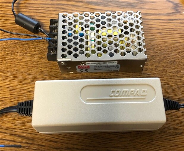
What other parts do you consider comparable to this product?: LM78XX, LM350 with a MOSFET driver and some fault circuits or COMPAQ laptop vehicle power supply adapter, driving a MW SD-15B-05 DC to DC converter, for 5V 3A output
What were the biggest problems encountered?: No problems encountered.
Detailed Review:
I was looking for a good power supply to use a Raspberry Pi in my truck, and this road test came along just in time.
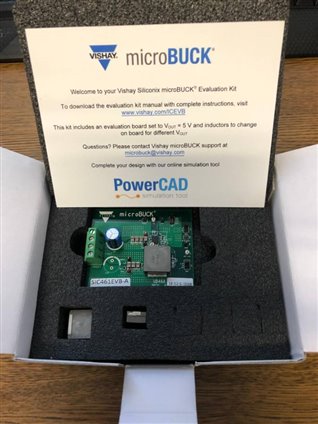
Unboxing:
The VISHAY Power IC Evaluation Board SIC461EVB-A came in a nice foam lined box, and included two extra inductors, 3.3uh and 10uh.
My board has a 5.6uh installed and the output voltage was set to 5VDC.
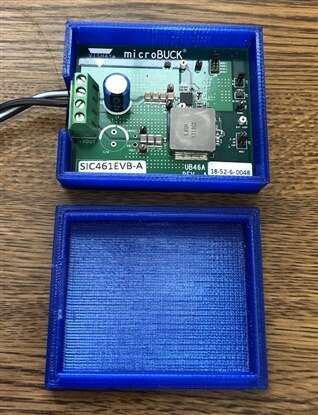
Enclosure:
Because I want to use this in my truck, I made a simple 3D printed enclosure.
One con for this board is a lack of mounting holes.
Initial Testing:
I used a variable power supply on the input lines to check the output voltage.
The advertised input voltage from the specification data sheet:
>> Single supply operation from 4.5 V to 60 V input voltage for SiC461 and SiC462, and 55 V for SiC471 and SiC472
My board shuts down below 9.5VDC on the input. I haven't tried to change any of the factory settings for now.
Since I'm planning to use the board in an automotive application, 9.5V-16 should be fine.
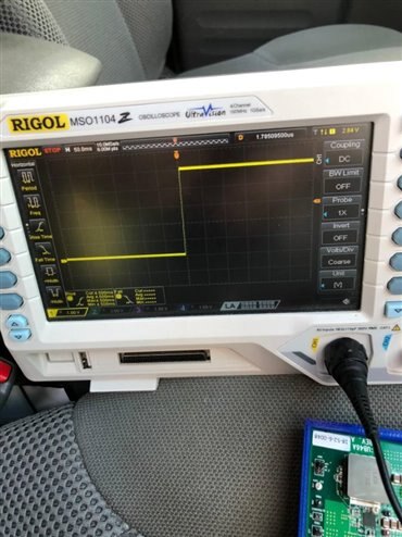
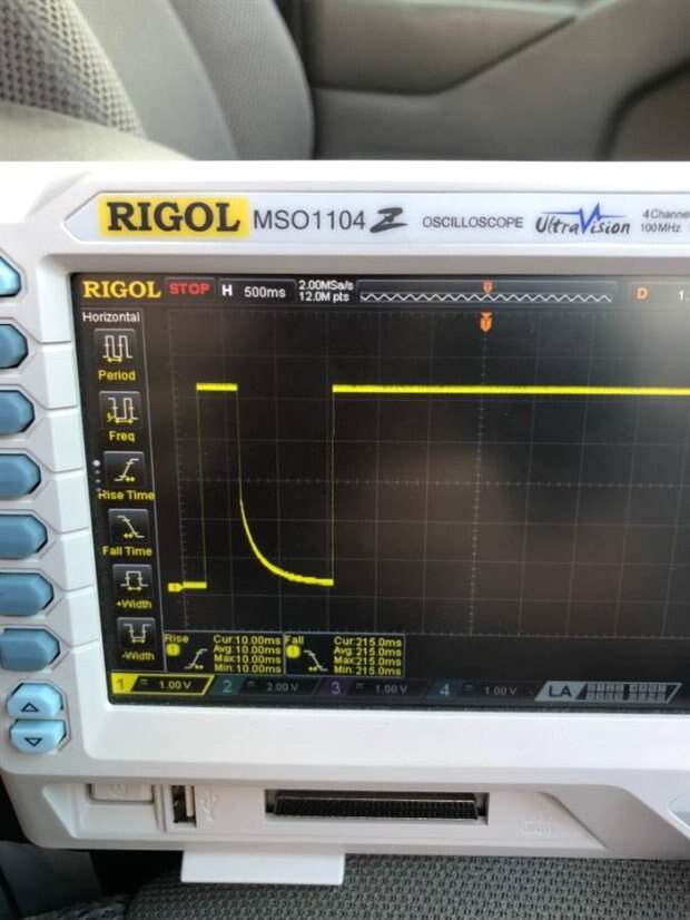
I wanted to see how the board started up and shut down, so I connected an oscilloscope to the output and a 4S 14.8VDC LiPo on the input.
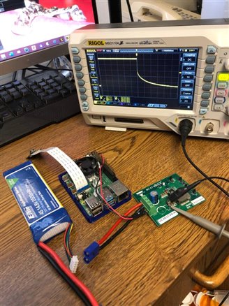
I set the trigger for rising edge capture and plugged in the LiPo battery.
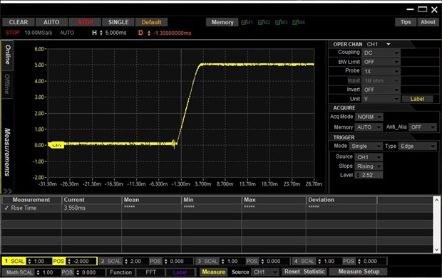
The rise time with no load was 3.95ms, with a RPi 4 as a load, the rise time was slightly longer.
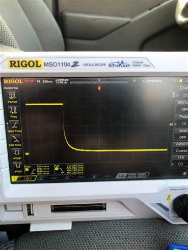
(Note the scale on the above graph is 5ms/div and 1ms/div below)
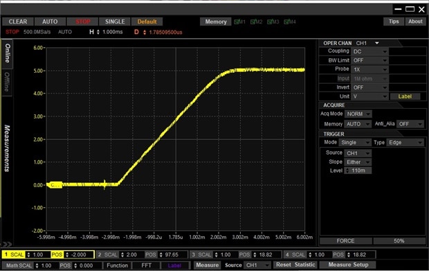
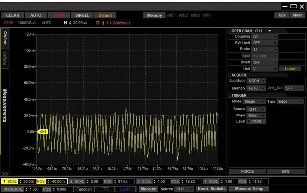
I measured about +-20mv ripple on the DC. The background noise on the scope is +-850uv with the probe grounded.
The fall time with no load was very long >10s. The fall time with the RPi 4 connected dropped quickly to about 2.5VDC, then fell slowly to 0V.
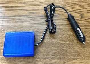
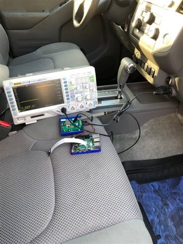
Vehicle Test:
The next test was to plug the microBUCK board into my truck cigarette lighter port and see how it handles ignition noise.
Here's the setup:
The Keyon ACC test looked similar to the battery test on the bench.
Key off voltage drop was also similar to battery test
The Keyon crank and start test had two starts with a dropout, but it followed the same patterns as before.
The Raspberry Pi didn't seem to mind the double start, although it could be a problem depending on where in the boot cycle it is when the power drops out.
I will need to investigate this further, maybe add a power switch or a larger output cap for vehicle starting.
This is an ongoing project, and I'm still building up the final system, but I believe the VISHAY microBUCK will work well for this application.
My original solution was a COMPAQ laptop vehicle power supply adapter, driving a MW SD-15B-05 DC to DC converter, for 5V 3A output.
Summary:
The VISHAY Power IC Evaluation Board SIC461EVB-A seems to work as advertised, although I haven't tried to modify the board for different voltages
or otherwise change the factory configuration since it fits my application as received.
I may only need 3-4A depending on how I set up my IR LED array for the night vision security camera feature.
I will update this road test as I build more of the system, so far the board works well. I'll do some thermal tests and efficiency also.
Thanks VISHAY and Element14 for letting me evaluate this board.


