RoadTest: Raspberry Pi Pico
Author: robogary
Creation date:
Evaluation Type: Development Boards & Tools
Did you receive all parts the manufacturer stated would be included in the package?: True
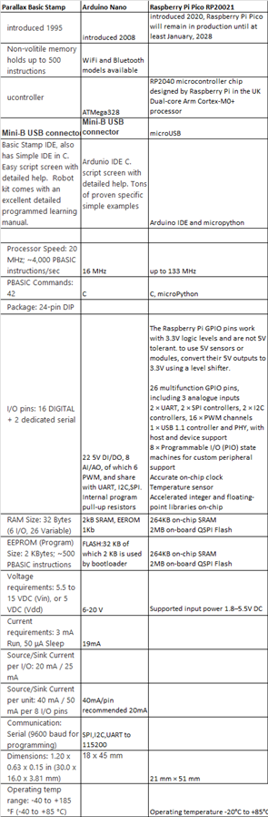
What other parts do you consider comparable to this product?: For robotics Parallax BoEBot and Arduino Nano.
What were the biggest problems encountered?: GPIO pins silk screen is on bottom. Had to glue a printout pin chart next to the Pico to track GPIO.
Detailed Review:
I run a robotics and makers club at the local library.
My Road Test Mission: Build a simple robot(s) using RPi Pico, record experience and compare with other beginner robot platforms.
Comparative beginner robot platforms – Parallax BoeBot (Basic Stamp with PBASIC) , Arduino Nano
Comparative matrix of RP2020 controllers: Adafruit & Sparkfun. MicroBit and CircuitPython weren’t considered for this road test, altho robots can be built with them, they really are better suited for premade accessory boards.
Road Test Results In a nutshell:
Raspberry Pi Pico blows previous microcontrollers for robots out of the water !
The analog and PWM resolution is so much better in the Pico, and easy to program. Reliably driving servos and H bridges is a piece of cake !
The book "Getting Started with MicroPython on Raspberry Pi Pico" is very helpful.
I hadnt even got to loading advanced features like AI or generic I2C shields to the Pico, but it will be on the list.
internally programmed pull up and pull down resistors are really handy !
Here is my first pass robot in action: https://youtu.be/7ty-Tb7d824
The second version, named Beetlebot, can be seen operating at this link: https://youtu.be/wE7IzgW8qr4
Versiion 2 adds a HC-SR04 ultrasonic sensor in the rear for backing up collision avoidance and makes all backup and turning times random,
its acts more like a bug, at least thats what kitty tells me :-) and BeetleBot wont get stuck in corners.
Tutorials and online references:
https://hackspace.raspberrypi.org/books/micropython-pico
https://www.raspberrypi.org/documentation/rp2040/getting-started/
https://www.tomshardware.com/how-to/program-raspberry-pi-pico-with-arduino-ide this link has the help to install the Arduino version needed for Pico programming on a Raspberry Pi
https://www.tomshardware.com/news/raspberry-pi-pico-tutorials-pinout-everything-you-need-to-know
To clear out Arduino (or micropython) load on the RPi Pico, use flash_nuke.uf2 , found at :
Getting Started with RP2040 – Raspberry Pi
This is the Thonny Python robot program:
from machine import Pin, PWM
import utime
LHSWhisker= Pin(14, machine.Pin.IN,machine.Pin.PULL_DOWN)
RHSWhisker= Pin(13, machine.Pin.IN,machine.Pin.PULL_DOWN)
LHSWhiskerLED= Pin(12, machine.Pin.OUT)
RHSWhiskerLED= Pin(11, machine.Pin.OUT)
AliveLED = Pin(25,machine.Pin.OUT)
LHSservo = PWM(Pin(16))
RHSservo = PWM(Pin(17))
# 50 Hz is 20 msec period
LHSservo.freq(50)
RHSservo.freq(50)
# 100% duty of PWM is 65200 counts
# 2 ms of 20 ms is 10% for full spd FWD
# ( 1.5 ms / 20 ms ) * 65200 = 4875 for servo zerospeed
# 1 ms of 20 ms is full spd rev , .05* 65200
zerospd = 4875
LHS_FullSpd = 3250 # LHS side servo is mounted opposite so gets a reversed reference
RHS_FullSpd = 6500
LHS_TopSpdRev = 6500
RHS_TopSpdRev = 3250
AliveLED.value(1)
while True:
AliveLED.toggle()
LHSservo.duty_u16(LHS_FullSpd) #top speed forward on LHS
RHSservo.duty_u16(RHS_FullSpd) # top spd fwd on RHS
# zerospeed = 4875
# if no action on the whiakers go straight
if ((LHSWhisker.value() ==0) & (RHSWhisker.value() ==0)):
LHSWhiskerLED.value(0)
if LHSWhisker.value() ==1:
LHSWhiskerLED.value(1)
LHSservo.duty_u16(LHS_TopSpdRev) #top speed rev on LHS
RHSservo.duty_u16(RHS_TopSpdRev) # top spd rev on RHS
utime.sleep(2)
# back up tthen right turn
LHSservo.duty_u16(LHS_FullSpd) #top speed forward on LHS
RHSservo.duty_u16(zerospd) # zerospeed on RHS
utime.sleep(2)
LHSservo.duty_u16(LHS_FullSpd) #top speed forward on LHS
RHSservo.duty_u16(RHS_FullSpd) # top spd fwd on RHS
if RHSWhisker.value() ==0:
RHSWhiskerLED.value(0)
if RHSWhisker.value() ==1:
RHSWhiskerLED.value(1)
LHSservo.duty_u16(LHS_TopSpdRev) #top speed rev on LHS
RHSservo.duty_u16(RHS_TopSpdRev) # top spd rev on RHS
utime.sleep(2)
# turn right
LHSservo.duty_u16(zerospd) # zerospeed on LHS
RHSservo.duty_u16(RHS_FullSpd) # top spd fwd on RHS
utime.sleep(2)
LHSservo.duty_u16(LHS_FullSpd) #top speed forward on LHS
RHSservo.duty_u16(RHS_FullSpd) # top spd fwd on RHS
MY usual PC: Install Arduino 1.8.15 on my W10 PC, wouldn’t connect COM PORT to Raspberry Pi Pico or compile Arduino example code without errors.
My Raspbeery Pi 3B: Install Arduino 2.1.05 on my Raspberry Pi, then following update instructions on: https://www.tomshardware.com/how-to/program-raspberry-pi-pico-with-arduino-ide. .
https://www.raspberrypi-spy.co.uk/2020/12/install-arduino-ide-on-raspberry-pi/
Step 5 failed, user “pi” doesn’t exist, but does. Arduino 2.1.05 is so old, it doesn’t resemble the instruction’s screen shots. Uninstall & reinstall per Tom’s instructions. Tried a couple different ways to install, all failed.
My backup PC: Fresh Arduino load on a different W10 PC that never had Arduino IDE installed, installed 1.8,15.
Pico GP25 lit, but I had it used as a PU LED, so did BOOTSEL. ISE didn’t see COM port. Recycled connection and it worked for a second ! Pico connected to COM3 ! It errord on upload on Example BLINK. Did a BOOTSEL and NukeFlash. Installed pico-setup-windows-.0.3.1-x86.exe on PC from Tom’s hardware without positive effect
NOTE: Raspberry Pi Pico has 40 pins. It doesnt fit on a177 hole breadboard. A minimum of 400 hole breadboard is needed.

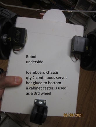
Robot photos: a 7.4v Lipo powers the robot. A Buck boot power supply converts 7.4 V to 5.5V to a forward biased diode.
The diode output is fed to the Rspberry Pi Pico VSYS. The diode blocks 5V from backfeeding the robot from the Pico USB port when plugged in from the programming PC.
Level shifters are used in between the 3V GPIO pins to the servo 5V signal pins.
With a working mobile platform, ping sensors, PixyCams, GPS, QTIs, etc can be easily added to enhance the functionality of the robot.


Here is the Pico robot V1 in action: https://youtu.be/7ty-Tb7d824
The second version, named Beetlebot, can be seen operating at this link: https://youtu.be/wE7IzgW8qr4
Versiion 2 adds a HC-SR04 ultrasonic sensor in the rear for backing up collision avoidance and makes all backup and turning times random,
its acts more like a bug, at least thats what kitty tells me :-) and BeetleBot wont get stuck in corners.
This is the V2 python code:
# This code has the BeetleBot run FWD at top spped.
# If the LHS side whisker bumps an object, Beetbot backs up and makes a righthand turn to avoid it.
# The time BeetleBot backs up is random, from 1.5 seconds to 6 seconds,.
# It will stop backing up if an object is detected 7 inches from the
# HC-SR04 ping sensor in the reat of BeetleBot.
# If the RHS whisker encounters an object, the behavior is the same except Beetlebot turns left after backing up.
from machine import Pin, PWM
# Pin uses the GPIO value , not the actual pin number
import utime
import random
LHSWhisker= Pin(14, machine.Pin.IN,machine.Pin.PULL_DOWN)
RHSWhisker= Pin(13, machine.Pin.IN,machine.Pin.PULL_DOWN)
LHSWhiskerLED= Pin(12, machine.Pin.OUT)
RHSWhiskerLED= Pin(11, machine.Pin.OUT)
AliveLED = Pin(25,machine.Pin.OUT)
LHSservo = PWM(Pin(16))
RHSservo = PWM(Pin(17))
# 50 Hz is 20 msec period
LHSservo.freq(50)
RHSservo.freq(50)
# 100% duty of PWM is 65200 counts
# 2 ms of 20 ms is 10% for full spd FWD
# ( 1.5 ms / 20 ms ) * 65200 = 4875 for servo zerospeed
# 1 ms of 20 ms is full spd rev , .05* 65200
zerospd = 4875
LHS_FullSpd = 3250 # LHS side servo is mounted opposite so gets a reversed reference
RHS_FullSpd = 6500
LHS_TopSpdRev = 6500
RHS_TopSpdRev = 3250
AliveLED.value(1)
PingTrigger=Pin(9,Pin.OUT)
PingEcho=Pin(8,Pin.IN)
def Ping():
echotries=0
PingTrigger.low()
utime.sleep_us(2) # note sleep_us is for microsecs
PingTrigger.high()
utime.sleep_us(10)
PingTrigger.low()
while ((PingEcho.value() == 0) and (echotries<30)):
EchoStartTime = utime.ticks_us()
echotries=echotries+1
# This check bails out of the loop on a problem with a long echo or failed echo, I havent been able to prove its needed.
while PingEcho.value()==1:
EchoHeard = utime.ticks_us()
PingDeltaTime=EchoHeard-EchoStartTime
PingDistance_cm =(PingDeltaTime*.0343)/2 # sound is 343.2 m/s .0343 cm/usec
PingDistance_in=(PingDistance_cm)/2.54
#print ("Measured distance is ",PingDistance_cm, "cm" )
print ("Measured distance is ",PingDistance_in, "inches" )
#print ("Echotries =", echotries)
return PingDistance_in
def backup():
LHSservo.duty_u16(LHS_TopSpdRev) #top speed rev on LHS
RHSservo.duty_u16(RHS_TopSpdRev) # top spd rev on RHS
while True: #this is start of the main loop routine
AliveLED.toggle()
# if no action on the whiakers go straight
LHSservo.duty_u16(LHS_FullSpd) #top speed forward on LHS
RHSservo.duty_u16(RHS_FullSpd) # top spd fwd on RHS
# zerospeed = 4875
# if no action on the whiakers go straight, clear LEDs
if ((LHSWhisker.value() ==0) & (RHSWhisker.value() ==0)):
LHSWhiskerLED.value(0)
RHSWhiskerLED.value(0)
################ LHS whisker routine, backup and turn right
if LHSWhisker.value() ==1: #gotta latch this operation
LHSWhiskerLED.value(1)
count=1
while True: # using break to exit the loop
backup()
#Ping()
PingDistance=Ping()
utime.sleep(.2)
count=count+1
backuptime=random.randint(8,30) # backuptime is comprised as the number of 200msec cycles before breaking out of the backup loop
#print ("backuptime = ",backuptime)
print ("count = ",count)
print ("backuptime = ",backuptime)
#print ("LoopCycles= ",Loopcycles)
if (PingDistance<6):
break
if (count>backuptime):
break
# print ("ping distance = ",PingDistance)
# back up tthen right turn
RHturntime=random.uniform(.5,3)
LHSservo.duty_u16(LHS_FullSpd) #top speed forward on LHS
RHSservo.duty_u16(zerospd) # zerospeed on RHS
utime.sleep(RHturntime)
#on exit of LHS Whisker routine, go staright again
LHSservo.duty_u16(LHS_FullSpd) #top speed forward on LHS
RHSservo.duty_u16(RHS_FullSpd) # top spd fwd on RHS
## start RHS side whisker behavior definition
if RHSWhisker.value() ==0:
RHSWhiskerLED.value(0)
if RHSWhisker.value() ==1:
RHSWhiskerLED.value(1)
count=1
while True: # using break to exit the loop
backup()
#Ping()
PingDistance=Ping()
utime.sleep(.2)
count=count+1
backuptime=random.randint(8,30) # backuptime is comprised as the number of 200msec cycles before breaking out of the backup loop
#print ("backuptime = ",backuptime)
print ("RHScount = ",count)
print ("RHSbackuptime = ",backuptime)
if (PingDistance<6):
break
if (count>backuptime):
break
# print ("ping distance = ",PingDistance)
# turn left
LHturntime=random.uniform(.5,3)
LHSservo.duty_u16(zerospd) # zerospeed on LHS
RHSservo.duty_u16(RHS_FullSpd) # top spd fwd on RHS
utime.sleep(LHturntime)
LHSservo.duty_u16(LHS_FullSpd) #top speed forward on LHS
RHSservo.duty_u16(RHS_FullSpd) # top spd fwd on RHS


