element14 Community
element14 Community
    Register Log In
  • Site
  • Search
  • Log In Register
  • About Us
  • Community Hub
    Community Hub
    • What's New on element14
    • Feedback and Support
    • Benefits of Membership
    • Personal Blogs
    • Members Area
    • Achievement Levels
  • Learn
    Learn
    • Ask an Expert
    • eBooks
    • element14 presents
    • Learning Center
    • Tech Spotlight
    • STEM Academy
    • Webinars, Training and Events
    • Learning Groups
  • Technologies
    Technologies
    • 3D Printing
    • FPGA
    • Industrial Automation
    • Internet of Things
    • Power & Energy
    • Sensors
    • Technology Groups
  • Challenges & Projects
    Challenges & Projects
    • Design Challenges
    • element14 presents Projects
    • Project14
    • Arduino Projects
    • Raspberry Pi Projects
    • Project Groups
  • Products
    Products
    • Arduino
    • Avnet Boards Community
    • Dev Tools
    • Manufacturers
    • Multicomp Pro
    • Product Groups
    • Raspberry Pi
    • RoadTests & Reviews
  • Store
    Store
    • Visit Your Store
    • Choose another store...
      • Europe
      •  Austria (German)
      •  Belgium (Dutch, French)
      •  Bulgaria (Bulgarian)
      •  Czech Republic (Czech)
      •  Denmark (Danish)
      •  Estonia (Estonian)
      •  Finland (Finnish)
      •  France (French)
      •  Germany (German)
      •  Hungary (Hungarian)
      •  Ireland
      •  Israel
      •  Italy (Italian)
      •  Latvia (Latvian)
      •  
      •  Lithuania (Lithuanian)
      •  Netherlands (Dutch)
      •  Norway (Norwegian)
      •  Poland (Polish)
      •  Portugal (Portuguese)
      •  Romania (Romanian)
      •  Russia (Russian)
      •  Slovakia (Slovak)
      •  Slovenia (Slovenian)
      •  Spain (Spanish)
      •  Sweden (Swedish)
      •  Switzerland(German, French)
      •  Turkey (Turkish)
      •  United Kingdom
      • Asia Pacific
      •  Australia
      •  China
      •  Hong Kong
      •  India
      •  Korea (Korean)
      •  Malaysia
      •  New Zealand
      •  Philippines
      •  Singapore
      •  Taiwan
      •  Thailand (Thai)
      • Americas
      •  Brazil (Portuguese)
      •  Canada
      •  Mexico (Spanish)
      •  United States
      Can't find the country/region you're looking for? Visit our export site or find a local distributor.
  • Translate
  • Profile
  • Settings
Transportation & Automotive
  • Technologies
  • More
Transportation & Automotive
Blog The Blinker in a Side-View Mirror - What's Inside?
  • Blog
  • Forum
  • Documents
  • Quiz
  • Polls
  • Members
  • Mentions
  • Sub-Groups
  • Tags
  • More
  • Cancel
  • New
Join Transportation & Automotive to participate - click to join for free!
  • Share
  • More
  • Cancel
Group Actions
  • Group RSS
  • More
  • Cancel
Engagement
  • Author Author: Jan Cumps
  • Date Created: 4 Sep 2020 2:32 PM Date Created
  • Views 3311 views
  • Likes 11 likes
  • Comments 10 comments
  • blinker
  • mercedes
  • power_led
  • leds
  • automotive
  • mirror
Related
Recommended

The Blinker in a Side-View Mirror - What's Inside?

Jan Cumps
Jan Cumps
4 Sep 2020

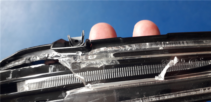
I had an accident last Monday on my way to meet balearicdynamics.

No one got hurt, but my side-view mirror is damaged.

There's a blinker in the mirror housing that's now exposed. A good opportunity to see how it's designed.

image


Here's  a view of an intact mirror. The part in the photo above is the horizontal construct you see in the middle.


image

image source: snippet from Mercedes commercial portal, fair use.


Mechanical Construct


The majority is plastic light piping. There's a PCB inside with two power LEDs.

The LEDs are at the far outer side of the construction.

Their light is diffused across the whole mirror width by that pipe. That pipe is molded in a way that the light appears as narrow vertical lines.

image

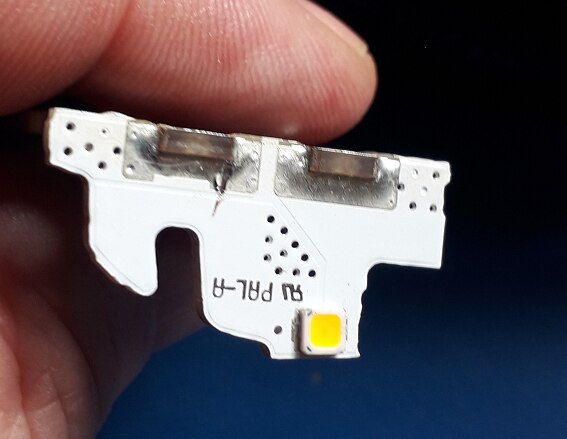
The two power LEDs are at opposite sides of their PCB. The pipe is wrapped around them and combines, then directs, the light of both LEDs.


Electronic Construct


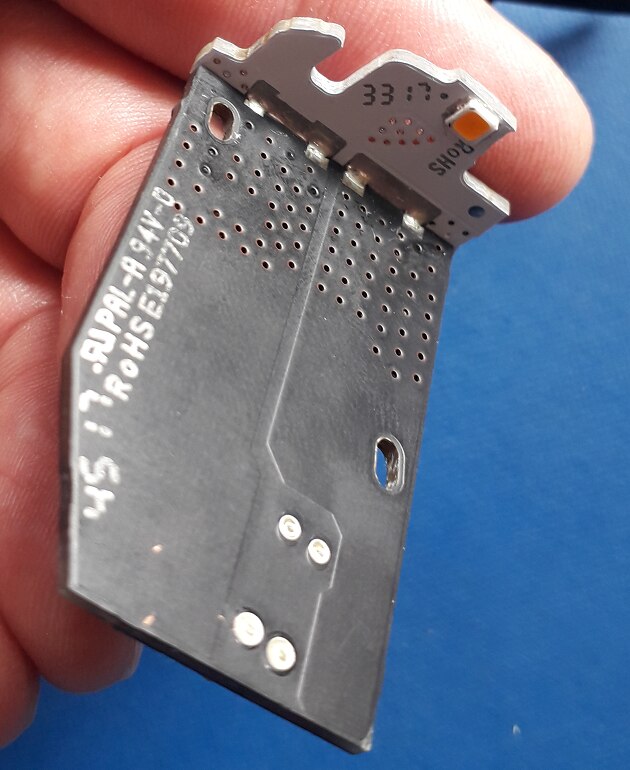
The device is built up with two PCBs. One, mounted flush with the mirror, has the driving circuit.


image


The other one, mounted at a 90° angle facing in the direction of the traffic, has an LED on each side.


image

The PCBs fit into each other like 2 puzzle pieces and are soldered together. Both as mechanical and electronic joints.

Both boards are double-sided. The driving circuit has all components on one side.


The Circuit

It's not hard at all to derive the schematics. All traces are beefy and easy to follow (see photo below).

image

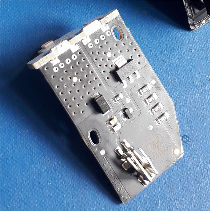
I could identify most of the components. The ones that I don't have a product code for, I know what type they are.

The result is a very simple circuit. As you can see, this is an imperfect but good enough current driver.

There's no blinking logic on-board. That's part of circuitry inside the car.

image

Components:

  • two capacitors at input (the first white one is probably input protection instead of a cap edit: I think it's a Würth or Murata TVS diode) are 95 nF together.
  • The diode in the 12 V path has markings PJ811K. Search brings me to the LittleFuse website, but I can't find a match.
  • The transistor is a bipolar BCP55BCP55, power NPN
  • The diode in the bias circuit is a SOT-23, with marking Z1W. I think it's a 4.6 V Zener (edit: it's a 4.7 V Zener: Nexperia BZX84-C4V7Nexperia BZX84-C4V7)
  • The bias resistor is 1K2.
  • The power LEDs have no identification
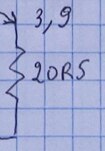
  • The emitter resistor is made out of 4 82 Ohm ones in parallel.


image

source: photo of the same design, from my own copy of The Art of Electronics


The LEDs take about 190 mA,

image


Circuit Analysis


(the measurements in the drawings are what I really measured. The text here uses the theoretical values. It's only 0.1 V difference).


The base of the transistor is kept at 4.7 V always, by the Zener diode.

The 1K2 resitor is there to bias the Zener. To give it the right current so that it is in its operation range.

That Zener bias current is: (11.4 V - 4.7 V) / 1200 Ohm = 6.7 V / 1200 Ohm = 5.6 mA (ignoring the base-emitter current that eats away a tiny bit of that).

5 mA is a typical Ir for these Zeners. The circuit biases the diode perfectly.


image


The emitter of a transistor, in this "common-emitter" design, is always one diode drop (the base-emitter diode) lower than the base.

4.7 V - 0.7 V = 4.0 V


image


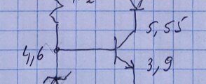
So we know that the voltage over the emitter resistor (in reality 4 resistors in parallel), is 4.0 V.

The resistor is 20.5 Ohm.

Ohms law says that I = U/R = 4.0 / 20.5 = 195 mA


image


Because the current through the collector is the same as the one through the emitter, we know that 195 mA will flow through the LEDs (ignore the base-emitter current. It's neglectable in this calculation).

Equation solved. This current driver circuit drives the LEDs at 195 mA.


image


Why four 82 Ohm resistors instead of a single 20.5 Ohm one?

The power dissipated by the resistor is 4.0 V * 195 mA = 780 mW.

It's cheaper to mount 4 resistors that can dissipate 250 mW than a single 1 W resistor.

image

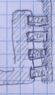
And the 82 Ohms is just a plain E12 series resistor.


How much power is dissipated in the transistor?

(For this calculation I use the measured values)

The collector is at 5.55 V.  The emitter is at 3.9 V

That gives a voltage drop of  (I'm rounding here) 5.6 V - 3.9 V = 1.7 V.

The current is 190 mA.

The transistor dissipates 1.7 V * 190 mA = 323 mW.

  • Sign in to reply

Top Comments

  • jw0752
    jw0752 over 5 years ago +5
    Only an engineer would turn a traffic accident into an electronics experiment. Bravo!! My car goes in to the garage on Tuesday for new tire pressure sensors. I already have it on my list to get the old…
  • DAB
    DAB over 5 years ago in reply to Jan Cumps +4
    Hi Jan, At the end you talk about diodes for wattage. DAB
  • Jan Cumps
    Jan Cumps over 5 years ago in reply to DAB +4
    DAB wrote: At the end you talk about diodes for wattage. I corrected it.
Parents
  • DAB
    DAB over 5 years ago

    Nice analysis Jan.


    DAB


    PS, I think you meant to say four resistors in parallel to get the wattage.

    • Cancel
    • Vote Up +3 Vote Down
    • Sign in to reply
    • More
    • Cancel
  • Jan Cumps
    Jan Cumps over 5 years ago in reply to DAB

    DAB  wrote:


    PS, I think you meant to say four resistors in parallel to get the wattage.

    I was refering to "E12 series": The Resistor E series tables of values.

    image

    • Cancel
    • Vote Up +2 Vote Down
    • Sign in to reply
    • More
    • Cancel
  • DAB
    DAB over 5 years ago in reply to Jan Cumps

    Hi Jan,


    At the end you talk about diodes for wattage.


    DAB

    • Cancel
    • Vote Up +4 Vote Down
    • Sign in to reply
    • More
    • Cancel
  • Jan Cumps
    Jan Cumps over 5 years ago in reply to DAB

    DAB  wrote:


    At the end you talk about diodes for wattage.


    I corrected it.

    • Cancel
    • Vote Up +4 Vote Down
    • Sign in to reply
    • More
    • Cancel
Comment
  • Jan Cumps
    Jan Cumps over 5 years ago in reply to DAB

    DAB  wrote:


    At the end you talk about diodes for wattage.


    I corrected it.

    • Cancel
    • Vote Up +4 Vote Down
    • Sign in to reply
    • More
    • Cancel
Children
No Data
element14 Community

element14 is the first online community specifically for engineers. Connect with your peers and get expert answers to your questions.

  • Members
  • Learn
  • Technologies
  • Challenges & Projects
  • Products
  • Store
  • About Us
  • Feedback & Support
  • FAQs
  • Terms of Use
  • Privacy Policy
  • Legal and Copyright Notices
  • Sitemap
  • Cookies

An Avnet Company © 2025 Premier Farnell Limited. All Rights Reserved.

Premier Farnell Ltd, registered in England and Wales (no 00876412), registered office: Farnell House, Forge Lane, Leeds LS12 2NE.

ICP 备案号 10220084.

Follow element14

  • X
  • Facebook
  • linkedin
  • YouTube