element14 Community
element14 Community
    Register Log In
  • Site
  • Search
  • Log In Register
  • Community Hub
    Community Hub
    • What's New on element14
    • Feedback and Support
    • Benefits of Membership
    • Personal Blogs
    • Members Area
    • Achievement Levels
  • Learn
    Learn
    • Ask an Expert
    • eBooks
    • element14 presents
    • Learning Center
    • Tech Spotlight
    • STEM Academy
    • Webinars, Training and Events
    • Learning Groups
  • Technologies
    Technologies
    • 3D Printing
    • FPGA
    • Industrial Automation
    • Internet of Things
    • Power & Energy
    • Sensors
    • Technology Groups
  • Challenges & Projects
    Challenges & Projects
    • Design Challenges
    • element14 presents Projects
    • Project14
    • Arduino Projects
    • Raspberry Pi Projects
    • Project Groups
  • Products
    Products
    • Arduino
    • Avnet Boards Community
    • Dev Tools
    • Manufacturers
    • Multicomp Pro
    • Product Groups
    • Raspberry Pi
    • RoadTests & Reviews
  • Store
    Store
    • Visit Your Store
    • Choose another store...
      • Europe
      •  Austria (German)
      •  Belgium (Dutch, French)
      •  Bulgaria (Bulgarian)
      •  Czech Republic (Czech)
      •  Denmark (Danish)
      •  Estonia (Estonian)
      •  Finland (Finnish)
      •  France (French)
      •  Germany (German)
      •  Hungary (Hungarian)
      •  Ireland
      •  Israel
      •  Italy (Italian)
      •  Latvia (Latvian)
      •  
      •  Lithuania (Lithuanian)
      •  Netherlands (Dutch)
      •  Norway (Norwegian)
      •  Poland (Polish)
      •  Portugal (Portuguese)
      •  Romania (Romanian)
      •  Russia (Russian)
      •  Slovakia (Slovak)
      •  Slovenia (Slovenian)
      •  Spain (Spanish)
      •  Sweden (Swedish)
      •  Switzerland(German, French)
      •  Turkey (Turkish)
      •  United Kingdom
      • Asia Pacific
      •  Australia
      •  China
      •  Hong Kong
      •  India
      •  Korea (Korean)
      •  Malaysia
      •  New Zealand
      •  Philippines
      •  Singapore
      •  Taiwan
      •  Thailand (Thai)
      • Americas
      •  Brazil (Portuguese)
      •  Canada
      •  Mexico (Spanish)
      •  United States
      Can't find the country/region you're looking for? Visit our export site or find a local distributor.
  • Translate
  • Profile
  • Settings
Circuit Protection
  • Technologies
  • More
Circuit Protection
Forum Roast My Circuit:  LiPo Battery Protection for Raspberry Pi
  • Blog
  • Forum
  • Documents
  • Quiz
  • Events
  • Polls
  • Files
  • Members
  • Mentions
  • Sub-Groups
  • Tags
  • More
  • Cancel
  • New
Join Circuit Protection to participate - click to join for free!
Actions
  • Share
  • More
  • Cancel
Forum Thread Details
  • Replies 8 replies
  • Subscribers 68 subscribers
  • Views 2337 views
  • Users 0 members are here
  • raspberry pi
  • regulator
Related

Roast My Circuit:  LiPo Battery Protection for Raspberry Pi

Sean_Miller
Sean_Miller over 4 years ago

I dreamed up a circuit that would prevent my Raspberry Pi project from damaging its LiPo battery.  A 3 cell LiPo should not go below around 10V or it will balloon and become unusable - if not a fire hazard.


The Pi and circuit work together to shutdown cleanly and disconnect the LiPo entirely.


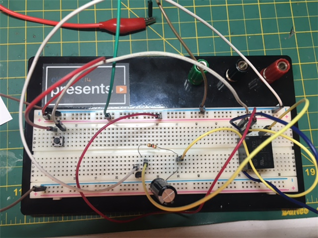
I bread boarded the basics and it appears to work fine.  Being that I scribbled it out of my noggin versus copying from a trusted source, it probably has all kinds of theoretical holes.
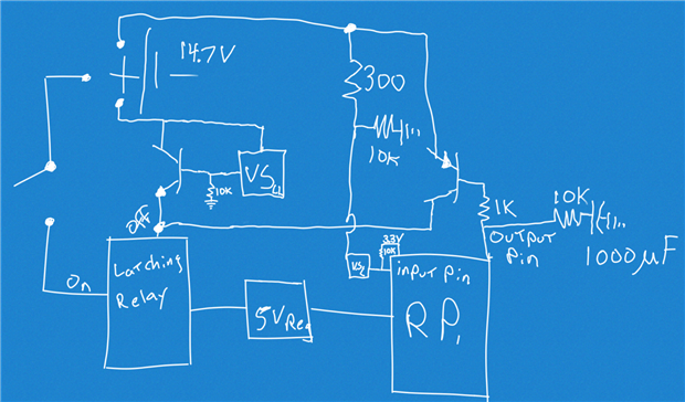
 

Here is the gist:

  • 14.8V LiPo is switched with a momentary switch.
  • When switched, power gets to a voltage regulator which powers the Raspberry Pi.  (The user knows to keep holding the switch until they hear the click of the relay.)
  • The Raspberry Pi outputs a pin high when it starts to boot which switches a NPN transistor.
  • The transistor takes the relay to ground latching in power to the regulator/Pi.  It's latched in as long as the Pi keeps that pin high.
  • The user can let go of the momentary switch once they hear the click as the relay is now latched in.
  • There is circuit block that monitors the main battery voltage and takes a pin low once it decreases to ~10V.
  • The Pi detects this and takes action to alert the user and shutdown safely.
  • A 1000uF capacitor is on the signal line so that the circuit will remain latched for 20 Seconds more to give the Pi time to finish the shutdown process after it takes the signal pin low.


So, please roast my circuit - what could be better (not the crappy schematic - but the design/components)?


image


image


Thanks,

Sean

  • Sign in to reply
  • Cancel

Top Replies

  • Gough Lui
    Gough Lui over 4 years ago +3
    Relays are horribly power inefficient - the draw of the coil could easily add several tens to hundreds of mA to your power consumption. Perhaps consider buying a "latching" relay if you can - those only…
  • Gough Lui
    Gough Lui over 4 years ago in reply to Sean_Miller +2
    Interesting sketch ... but perhaps there are still improvements afoot, at least from my point of view. The voltage supervisor function isn't all that clear (in terms of how it is implemented) - most latching…
  • Sean_Miller
    Sean_Miller over 4 years ago in reply to Gough Lui +2
    Good point on the voltage supervisor blocks. They would at least have some micro amps. I'll move it's inputs downstream of the relay as you said. Another good point on the flyback diode. I remember doing…
  • Gough Lui
    Gough Lui over 4 years ago

    Relays are horribly power inefficient - the draw of the coil could easily add several tens to hundreds of mA to your power consumption. Perhaps consider buying a "latching" relay if you can - those only need a "pulse" of power on a coil to change the state, thus not taking any power while otherwise running. Electromechanical relays may be a bit vulnerable to vibration and bumps ...


    Not sure the 1000uF would keep the circuit latched that long ... relays are pretty power hungry.


    To be honest, you're probably better off with a proper 3s battery pack protector circuit that will disconnect the battery regardless - no intervention from a Pi or anything, as that could crash or hang. Such a circuit would unconditionally protect the battery while only using very small amounts of current (tens of uA). Usually they also incorporate cell balancing as well, but need connections to the intermediate tap points. They often also provide short circuit and over-voltage protection too.


    Then you're basically reduced to having the RPi detect the voltage of the battery and shut down below a given voltage. Something like a cheap uC with an ADC input could provide that data to the Pi, or if you're daring, an ADC hooked into an I2C/SPI port in much the same way.


    In essence, that would achieve a similar result, but minus the mechanical relay and power consumption associated with it, and the risk of software crashes causing the protection to fail.


    - Gough

    • Cancel
    • Vote Up +3 Vote Down
    • Sign in to reply
    • Cancel
  • Sean_Miller
    Sean_Miller over 4 years ago in reply to Gough Lui

    I like the sound of the latching relay.  My breadboarded circuit drew about 43mA, which is acceptable for the application, but 0mA - now that's a bargain.


    The capacitor in my circuit is actually on the base of the transistor that is completing grounding the relay.  So, it is very slow to drain.  The breadboard proved it to be about 20 seconds to drain through the base - plenty of time for the Pi to shutdown cleanly after the pin voltage is dropped.


    To address the software failure concern, I'll add a second voltage supervisor.  One supervisor will use a voltage divider as a LOW alarm that triggers a user warning and a shutdown timer for a clean shutdown by the PI.  The other will be monitoring for the LOW-LOW interlock which simply punches the latching relay regardless of the PI state.  Ideally, that one would never be reached.  This will be the best of both worlds and will prevent SD card corruption from hard power downs.


    I'll update the schematic once I find one of those latching relays.


    Thanks for the assessment.

    Sean

    • Cancel
    • Vote Up +1 Vote Down
    • Sign in to reply
    • Cancel
  • Sean_Miller
    Sean_Miller over 4 years ago in reply to Sean_Miller

    This latching relay looks like a winner - plenty of amps, lapping, and works good with my battery:


         G5RLK1EDC12 - Omron - General Purpose Relay, G5RL-K Series, Power (newark.com)

    • Cancel
    • Vote Up +1 Vote Down
    • Sign in to reply
    • Cancel
  • Gough Lui
    Gough Lui over 4 years ago in reply to Sean_Miller

    Indeed, for applications where the relay is staying "on" for long periods, latching relays are the norm.


    Sorry, I didn't notice the capacitor was on the transistor - you might want to make sure your Pi turns "off" the supply by going high impedance rather than low on the pin that is connected to the transistor base/RC combination, otherwise the Pi could try to discharge the cap via the GPIO which would probably burn it out or make it very unhappy (depending on where your resistors are placed).


    - Gough

    • Cancel
    • Vote Up +1 Vote Down
    • Sign in to reply
    • Cancel
  • Sean_Miller
    Sean_Miller over 4 years ago

    Concept art for the new circuit.


    I'm using a dual N&P channel MOSFET surface mount chip along with two voltage supervisors.


    The clean software shutdown is triggered by a voltage supervisor that is sensing off a voltage divider.  I call it the Low Alarm point.


    To be safe from glitches, a transistor only branch in the circuit handles the Low Low condition and does a hard shutdown.  Hopefully, it will never be needed.


    See ya',

    Sean


    image

    • Cancel
    • Vote Up 0 Vote Down
    • Sign in to reply
    • Cancel
  • Gough Lui
    Gough Lui over 4 years ago in reply to Sean_Miller

    Interesting sketch ... but perhaps there are still improvements afoot, at least from my point of view. The voltage supervisor function isn't all that clear (in terms of how it is implemented) - most latching relays only expect to have a short "pulse" input, so if it's supposed to be turned off, then perhaps having it hooked to the battery long term will cause current drain from the battery through the voltage supervisor if its output just "remains high" (the opposite of what you want).


    Instead, I suggest you might have the voltage supervisors powered from the output of the latching relay itself, so if there is no "initial" pulse to start the circuit, everything is essentially open circuit. Likewise, same with the voltage divider for sense - the way you have it is it will always drain the battery over time (and not an insignificant drain at that). That also takes care of not having current drain through the voltage supervisor and its associated transistor when powering off - because as soon as enough current passes to latch the relay off, it will cut power to the supervisor circuit itself.


    Another thing that you're probably missing is the "flyback" diodes for the relay coils - when you de-energize coils, the inductive kick you get results in a high voltage spike that will eventually destroy most semiconductors. A diode placed in reverse across the coil is customary to "snub" out this spike.


    - Gough

    • Cancel
    • Vote Up +2 Vote Down
    • Sign in to reply
    • Cancel
  • Sean_Miller
    Sean_Miller over 4 years ago in reply to Gough Lui

    Good point on the voltage supervisor blocks.  They would at least have some micro amps.  I'll move it's inputs downstream of the relay as you said. 


    Another good point on the flyback diode.  I remember doing this with my motor circuits.  I'll add it in.


    This whole circuit block is being added to a bigger circuit that also contains a speaker amplifier, display screen port, and some auxiliary headers for I2C devices.  Looks like it will all fit well in my camera project reducing the cobbled together protoboards I have now to 1/3rd the footprint. 


    The board is basically a Pi Hat that will make my future battery powered/portable projects much more end user friendly.  I'll share it on OSHPARK.


    Thanks for the roasting!

    Sean

    • Cancel
    • Vote Up +2 Vote Down
    • Sign in to reply
    • Cancel
  • Sean_Miller
    Sean_Miller over 4 years ago

    Still a work in progress, but its coming together...


    image

    • Cancel
    • Vote Up 0 Vote Down
    • Sign in to reply
    • Cancel
element14 Community

element14 is the first online community specifically for engineers. Connect with your peers and get expert answers to your questions.

  • Members
  • Learn
  • Technologies
  • Challenges & Projects
  • Products
  • Store
  • About Us
  • Feedback & Support
  • FAQs
  • Terms of Use
  • Privacy Policy
  • Legal and Copyright Notices
  • Sitemap
  • Cookies

An Avnet Company © 2025 Premier Farnell Limited. All Rights Reserved.

Premier Farnell Ltd, registered in England and Wales (no 00876412), registered office: Farnell House, Forge Lane, Leeds LS12 2NE.

ICP 备案号 10220084.

Follow element14

  • X
  • Facebook
  • linkedin
  • YouTube