element14 Community
element14 Community
    Register Log In
  • Site
  • Search
  • Log In Register
  • Community Hub
    Community Hub
    • What's New on element14
    • Feedback and Support
    • Benefits of Membership
    • Personal Blogs
    • Members Area
    • Achievement Levels
  • Learn
    Learn
    • Ask an Expert
    • eBooks
    • element14 presents
    • Learning Center
    • Tech Spotlight
    • STEM Academy
    • Webinars, Training and Events
    • Learning Groups
  • Technologies
    Technologies
    • 3D Printing
    • FPGA
    • Industrial Automation
    • Internet of Things
    • Power & Energy
    • Sensors
    • Technology Groups
  • Challenges & Projects
    Challenges & Projects
    • Design Challenges
    • element14 presents Projects
    • Project14
    • Arduino Projects
    • Raspberry Pi Projects
    • Project Groups
  • Products
    Products
    • Arduino
    • Avnet & Tria Boards Community
    • Dev Tools
    • Manufacturers
    • Multicomp Pro
    • Product Groups
    • Raspberry Pi
    • RoadTests & Reviews
  • About Us
  • Store
    Store
    • Visit Your Store
    • Choose another store...
      • Europe
      •  Austria (German)
      •  Belgium (Dutch, French)
      •  Bulgaria (Bulgarian)
      •  Czech Republic (Czech)
      •  Denmark (Danish)
      •  Estonia (Estonian)
      •  Finland (Finnish)
      •  France (French)
      •  Germany (German)
      •  Hungary (Hungarian)
      •  Ireland
      •  Israel
      •  Italy (Italian)
      •  Latvia (Latvian)
      •  
      •  Lithuania (Lithuanian)
      •  Netherlands (Dutch)
      •  Norway (Norwegian)
      •  Poland (Polish)
      •  Portugal (Portuguese)
      •  Romania (Romanian)
      •  Russia (Russian)
      •  Slovakia (Slovak)
      •  Slovenia (Slovenian)
      •  Spain (Spanish)
      •  Sweden (Swedish)
      •  Switzerland(German, French)
      •  Turkey (Turkish)
      •  United Kingdom
      • Asia Pacific
      •  Australia
      •  China
      •  Hong Kong
      •  India
      •  Korea (Korean)
      •  Malaysia
      •  New Zealand
      •  Philippines
      •  Singapore
      •  Taiwan
      •  Thailand (Thai)
      • Americas
      •  Brazil (Portuguese)
      •  Canada
      •  Mexico (Spanish)
      •  United States
      Can't find the country/region you're looking for? Visit our export site or find a local distributor.
  • Translate
  • Profile
  • Settings
Circuit Protection
  • Technologies
  • More
Circuit Protection
Forum Simple FET question
  • Blog
  • Forum
  • Documents
  • Quiz
  • Events
  • Polls
  • Files
  • Members
  • Mentions
  • Sub-Groups
  • Tags
  • More
  • Cancel
  • New
Join Circuit Protection to participate - click to join for free!
Actions
  • Share
  • More
  • Cancel
Forum Thread Details
  • Replies 6 replies
  • Subscribers 71 subscribers
  • Views 963 views
  • Users 0 members are here
Related

Simple FET question

billabott
billabott over 12 years ago
image

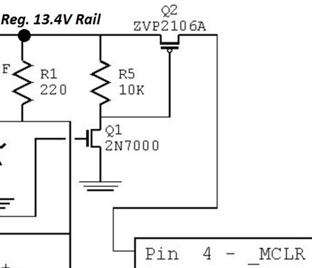
I will be double checking any opinion with a Multimeter.  I ordered a less expensive part for this project "by mistake" from Newark.   The N-Channel FET equivalent of Q2 (ZVN2106A) was ordered and was 33% of the cost of the P-Channel FET.  The gate of Q1 is controlled by a signal coming over the Parallel port of a desktop PC.  It seems to me that Q1 and R5 can be swapped and everybody will be happy.   Am I correct?

  • Sign in to reply
  • Cancel

Top Replies

  • shabaz
    shabaz over 12 years ago in reply to mconners +2
    I don't have a youtube video, but here is a pic of a SOT-23-sized device, and an 0603 resistor on stripboard. An alternative is to use the board with separated solder holes (see pic below), and use very…
  • johnbeetem
    johnbeetem over 12 years ago in reply to shabaz +2
    Michael Kellett posted a link to a very nice TI adapter board that's an array of DIP adapters for small packages.
  • billabott
    billabott over 12 years ago in reply to shabaz +1
    Thanks for the feedback, guys. shabaz : That is interesting because I intend to use strip board with a lot of project builds and was wondering if it was possible to use the SMD size devices on that kind…
Parents
  • johnbeetem
    johnbeetem over 12 years ago

    If I understand your question correctly, you want to replace Q2 with an NFET and swap Q1 and R5 to get a higher voltage on the gate of Q2.


    If that's the case, I don't think it's going to work.  To turn on, an NFET requires that the gate voltage be higher than the source.  It must be higher by at least Vth, the threshold voltage.  However, this turns it on weakly: it's in saturation mode and Vsource will be at most Vgate - Vth.  To fully turn on the NFET, you need Vgate to be higher than both Vdrain and Vsource.  This puts the NFET in ohmic mode where it behaves like a resistor.  The higher the gate voltage, the lower the resistance.


    Your diagram uses a PFET for Q2 because it's easy to turn it on and off with a low voltage signal.  The disadvantage is that PFETs are far less efficient than NFETs, thus more expensive to get the same resistance.  So it's better to have Q2 be an NFET.  But in that case you need a charge pump to get the NFET's Vgate above Vdrain and Vsource.  "Hot swap" controller chips typically boost the NFET gate by 6-10V so that it turns on with low resistance.


    Wikipedia has a good article on MOSFETs describing modes of operation, but it doesn't show application circuits.

    • Cancel
    • Vote Up 0 Vote Down
    • Sign in to reply
    • Cancel
  • shabaz
    shabaz over 12 years ago in reply to johnbeetem

    Unfortunately there are not many TO-92 sized MOSFETS (either N-ch or P-ch), so that also makes them rare too, to compound the issue.

    I just tend to use SOT-23 sized SMD devices, because it is still possible to solder them to the stripboard side, if you cut a track and then

    mount the device so that it straddles a couple of rows.


    However, according to the schematic snippet, it looks like it is an MCLR pin of a microcontroller, so maybe this is a microcontroller

    programmer circuit?

    If so, you could check the current requirement, and possibly replace the P-ch with just a TO-92 sized PNP BJT (e.g. BC557). You should

    stick a small resistor (maybe 10k) in series with the base lead of the BJT. The rest of the circuit would then remain the same as

    the indicated image. This is all assuming that not much current (a few tens of mA) is needed to program this microcontroller.

    I think this may be the case.

    • Cancel
    • Vote Up 0 Vote Down
    • Sign in to reply
    • Cancel
  • billabott
    billabott over 12 years ago in reply to shabaz

    Thanks for the feedback, guys.


    shabaz:  That is interesting because I intend to use strip board with a lot of project builds and was wondering if it was possible to use the SMD size devices on that kind of board.  I wouldn't mind seeing some youtube video on the possibilities of "SMD on Strip board."


    After studying and researching with Google for a couple of hours, I have hedged my bet that JohnB is correct and purchased 50 of these SUPERTEX TP0606N3 P-Channel DMOS FET on ebay.  They appear to have the "Right Stuff" for $0.26 each and free shipping.  Besides, I had $9.26 in eBay cash to spend on something and these will, I think, fill my current and future needs for P-Channel DMOS FETs.


    MichaelC:  I uncovered the following web page that shines a light on the theory you and I have forgotten in the mists of time.  http://www.electronics-tutorials.ws/transistor/tran_8.html

      Seems that JohnB is one crack EE.  Slamming the gate shut on a P-Channel FET is trivial by pulling it to ground, just as the original circuit shows, because VG << Vs.  I will not claim to understand it deeply until I get my hands dirty with them.  image

    • Cancel
    • Vote Up +1 Vote Down
    • Sign in to reply
    • Cancel
  • mconners
    mconners over 12 years ago in reply to billabott

    Thanks Bill. Interesting link.


    Mike

    • Cancel
    • Vote Up 0 Vote Down
    • Sign in to reply
    • Cancel
  • shabaz
    shabaz over 12 years ago in reply to mconners

    I don't have a youtube video, but here is a pic of a SOT-23-sized device, and an 0603 resistor on stripboard.

    image

    An alternative is to use the board with separated solder holes (see pic below), and use very thin wire (called tefzel on the Farnell website, also known as kynar, and Fry's have it pre-cut and stripped, very convenient) for connecting up. The result looks like a nest of wires, but is ok for prototypes. I often combine that method with copper tape, because I can stick that down to act as power supply rails or just small pieces of tape as a 'landing zone' for a node where there are many connections. It becomes a bit delicate because the tape can lift, but as long as the board is not subjected to rough treatment it is ok. The tape is expensive but very little is used (I cut it halfway along it's length too, because I only need it to be a few mm wide). I use this 3M one, it stays stuck as long as you don't heat the tape for too long. Others may be just as effective, but I've not tried them.

    Regarding the technique, I think everyone has their own personal favorites. I have a cheap iron, but it is fairly mid-high power (50W) temperature controlled, and the bit is 1mm. I'd like to try a more advanced iron, but never got round to it.

    This is the size of it in relation to proto board holes:

    image

    The particular iron I have uses this tip.

    Once the SMD part is being held in the correct place (with tweezers), just touching the iron tip will deposit a small bit of solder to hold one end in place, then you can remove the tweezers, solder the remaining pins as normal, and then rework the first pin. Another method is to hold the SMD part and the solder simultaneously in one hand, if you can manage it. This is the grip I use:

    image

    It allows you to adjust the solder wire by a millimeter or two as you solder by just compressing some fingers, without losing the pressure on the tweezers.

    But actually the Supertex device you found looks perfect. I might get some because TO-92 is sometimes convenient for quick experiments. By the way, (you may probably know already anyway) it is good to solder in the resistors first and then solder the FET in last, so that the gate is protected. I'm not sure if that is being overcautious or if others do it too.

    Here is a pic of the tape method. It's not pretty (I was in a hurry). You can see two SMD inductors, and a couple of SMD diodes near the top. This was done on the plain side of normal stripboard, so it can be combined with normal wired components. The white wire is the tefzel/kynar wire mentioned earlier. If you want to use surface-mount ICs, you could glue an SMD adapter board on the plain side of stripboard too. And run the copper tape power planes three-dimensionally, from the surface of the stripboard and on to the

    adapter board. SMD IC adapter boards are depressingly expensive, since you need a variety at hand. I get mine from ebay, but even those are not ideal.

    image

    • Cancel
    • Vote Up +2 Vote Down
    • Sign in to reply
    • Cancel
  • johnbeetem
    johnbeetem over 12 years ago in reply to shabaz

    Michael Kellett posted a link to a very nice TI adapter board that's an array of DIP adapters for small packages.

    • Cancel
    • Vote Up +2 Vote Down
    • Sign in to reply
    • Cancel
Reply
  • johnbeetem
    johnbeetem over 12 years ago in reply to shabaz

    Michael Kellett posted a link to a very nice TI adapter board that's an array of DIP adapters for small packages.

    • Cancel
    • Vote Up +2 Vote Down
    • Sign in to reply
    • Cancel
Children
No Data
element14 Community

element14 is the first online community specifically for engineers. Connect with your peers and get expert answers to your questions.

  • Members
  • Learn
  • Technologies
  • Challenges & Projects
  • Products
  • Store
  • About Us
  • Feedback & Support
  • FAQs
  • Terms of Use
  • Privacy Policy
  • Legal and Copyright Notices
  • Sitemap
  • Cookies

An Avnet Company © 2025 Premier Farnell Limited. All Rights Reserved.

Premier Farnell Ltd, registered in England and Wales (no 00876412), registered office: Farnell House, Forge Lane, Leeds LS12 2NE.

ICP 备案号 10220084.

Follow element14

  • X
  • Facebook
  • linkedin
  • YouTube