


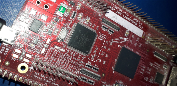
Goal: Continuously sample an ADC on a single thread microcontroller, with as little as possible CPU overhead. I'm trying to use internal timers and DMA to fill memory with samples, and leaving all processing power for working with that data.
|
This post is a side effect of porting a TI example for another controller of the Hercules family.
The example works, but it's useful to find out the settings done in the HAL utility. Those weren't documented so it took me some effort to sort those out.
That work to adapt from a Hercules RM46 to a TMS570LC43 is documented here.
Example's functionality: Hardware triggered sampling, DMA to move results into RAM.
One of the on-board ADCs is used to sample a signal. Results are moved to memory via DMA.
The trigger for each sample is a PWM signal generated by one of the on-board hardware timers.
HAL Configuration
The majority of the initialisation and driver generation is done via the HALCoGen utility.
Driver Enable
Two need to be enabled: the ADC and HET (timer) drivers.

The ADC 1 is used to sample. HET 1 (high-end-timer) for generating the hardware trigger at a fixed frequency.
Later in the post I will point out why the particular HET and a specific pin of that timer is used (giveaway: It 'll be HET1 pin 17).
ADC and HET clock frequency
To stay as close as possible to the original example, that runs on a different clock frequency, I changed prescalers:
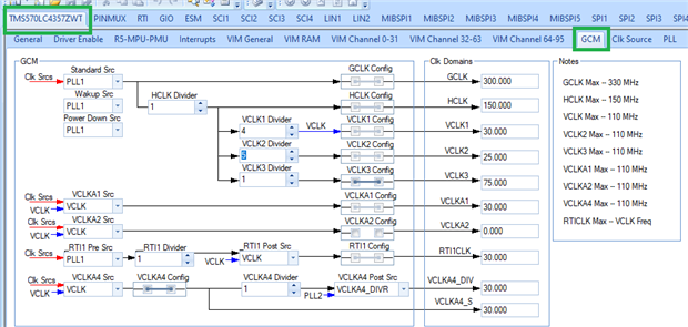
I didn't calculate. Just used settings until the timer and ADC frequencies (see later) matched the RM46 example.
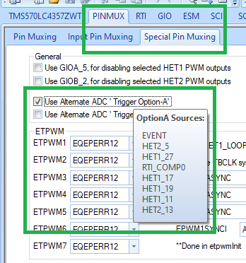
Configure the HET and DMA Interupt
Some of the Hercules members have specialised trigger options available in hardware.
One of those "easy-overrides" called Alternative ADC Trigger Options is that you can trigger ADC from a few other internal peripherals without external connections.
We want to use a clocked ADC sequence. HET is a good candidate to generate those trigger blips.
There are other peripherals that could be used with similar result: the real time interrupt ant the ePWM. Both are also able to generate timed interrupts to the ADC.
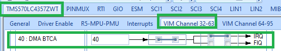
Also the DMA interrupt needs to be set.
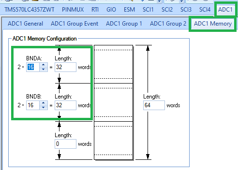
Configure Memory for DMA
This is a difficult exercise. I need to do some reading. I'll update the blog or write a follow up after that.
For DMA, the correct memory block must have correct cache attibutes.
A post I wrote about that earlier, that I'll reuse if possible: https://texasinstruments.hackster.io/jancumps/hercules-configure-memory-cache-for-dma-0945cd
Configure the Timer (HET)
HET1 pin 17 is used. It's one of the pins that are eligible to provide the internal alternate ADC interrupt.
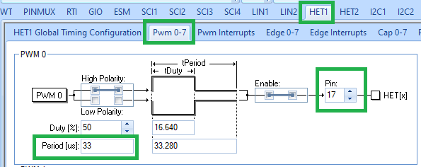
Although it can be tricky to work with the HET, configuring it to generate a 30 kHz PWM isn't.
You select one of the 7 PWM slots, set it to pin 17 and set the period (30 kHz = 33.3.. µs).
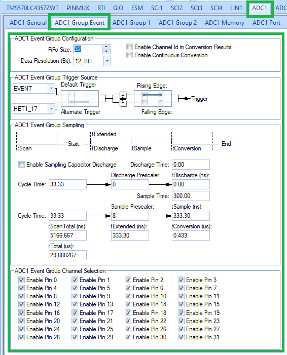
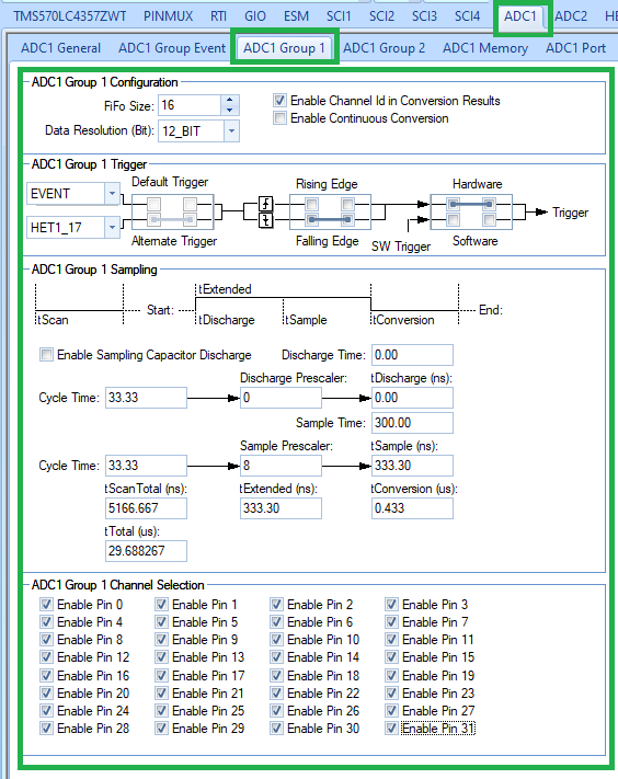
Configure ADC
The ADC 1 is the one we use. Here's the config:
Firmware
That's 1-to-1 portable without changes, except for the header file names that are different.
/* USER CODE BEGIN (0) */
#include "HL_adc.h"
#include "HL_het.h"
#include "HL_sys_dma.h"
#include "HL_sys_core.h"
/* USER CODE END */
The enable interrupt on the TMS570 takes a mandatory parameter extra. The info on hat this should be is a little cryptic.
One more todo
    // todo: check if parameter 3 i INTA or Lockstep-specific INTB
    dmaEnableInterrupt(DMA_CH0, BTC, DMA_INTA);
    dmaEnableInterrupt(DMA_CH1, BTC, DMA_INTA);
With these actions, I have firmware that compiles. Ready to load it and check with a debugger...
