Table of Contents
Introduction
This is a very short blog that simply builds on earlier work: Using Segment LCD and ADC with Renesas RA Microcontrollers
I was interested in finding a large segment LCD that could be read from several meters away, with dual number fields, so that things like (say) voltage and current could be displayed simultaneously, or time and temperature, or temperature and humidity, and so on.
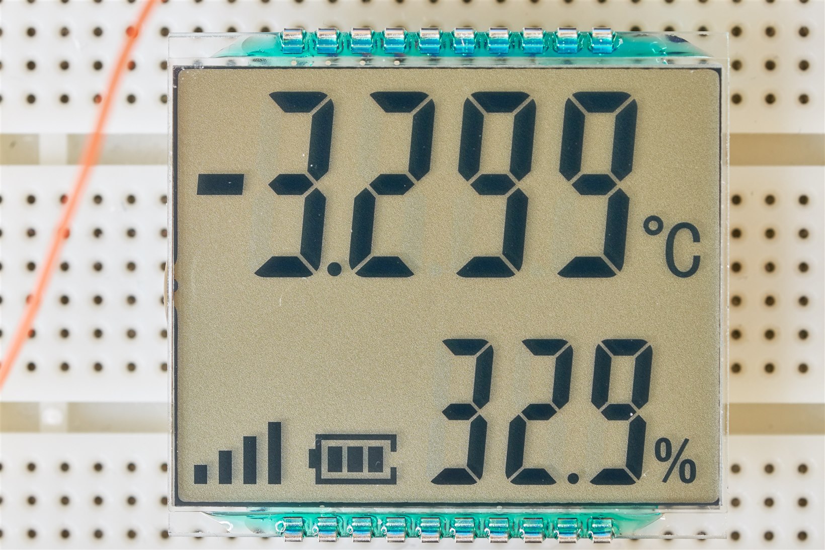
The display I used has digits at the top and bottom, which are 14 and 11 mm high respectively, and I can read them from a distance. I also liked that there were signal and battery level indicators that could come in handy.
The display comes in two compatible variants; one with a fully reflective backing sheet and another with a slightly translucent one for optional backlighting. The photo below shows the variant with no backlighting.

Please read the earlier blog for more detail on interfacing, configuring, and coding for segment LCDs with Renesas RA microcontrollers. This blog post merely shows how to pick almost any arbitrary segment LCD and get it working with the microcontroller. With LCDs with multiple fields, such as the one here, it is desirable to have functions that can update portions of the LCD without re-writing all the data for the rest of the display, so I figured writing a blog for such a scenario would be interesting.
LCD Connections
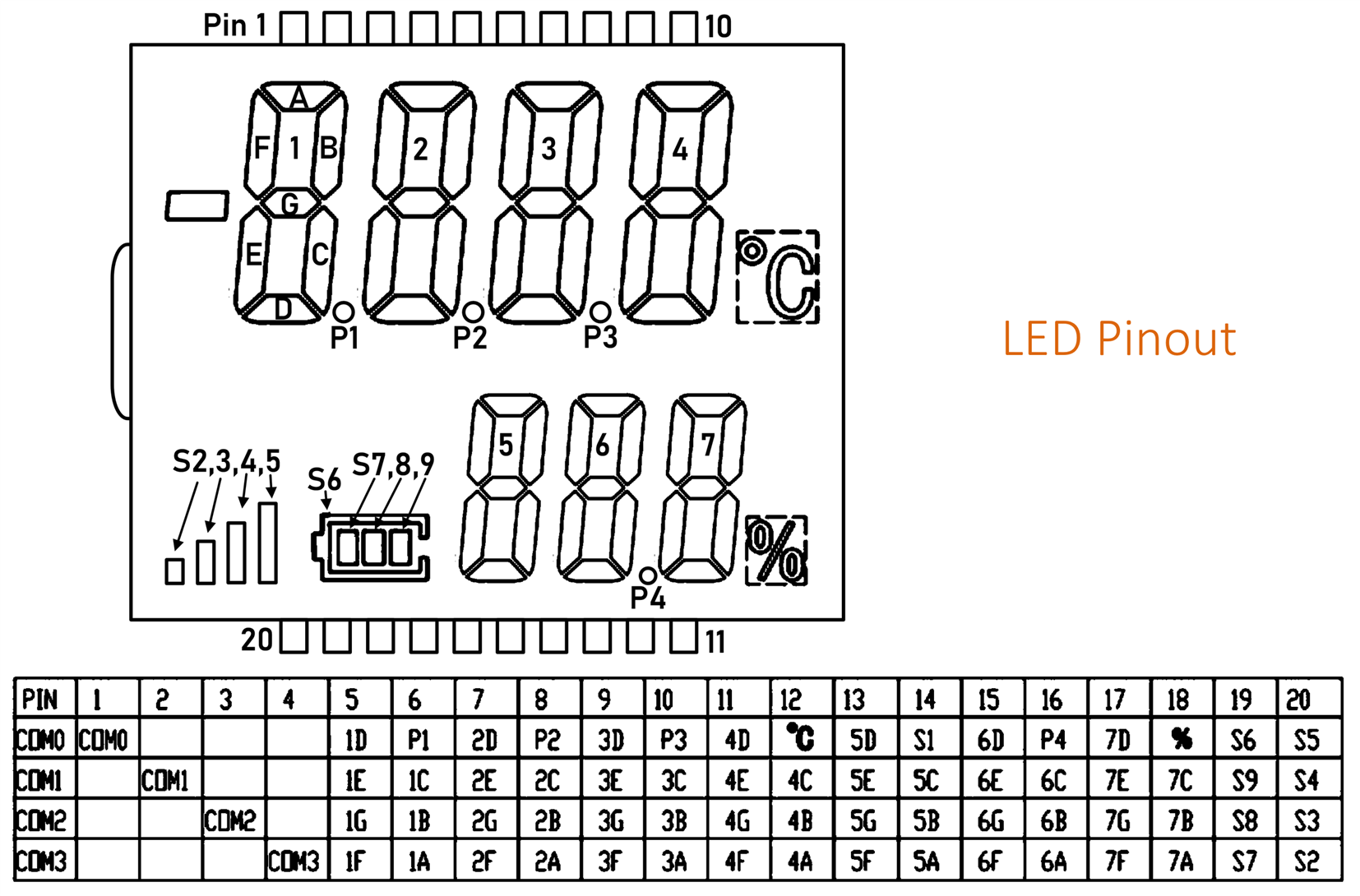
The LCD is wired up to the Renesas RA4M1 microcontroller in a similar way as described in the earlier blog post. The only difference is that the LCD used in this blog post has 20 pins (4 COM and 16 SEG pins) versus 12 pins (4 COM and 8 SEG) in the previous one.

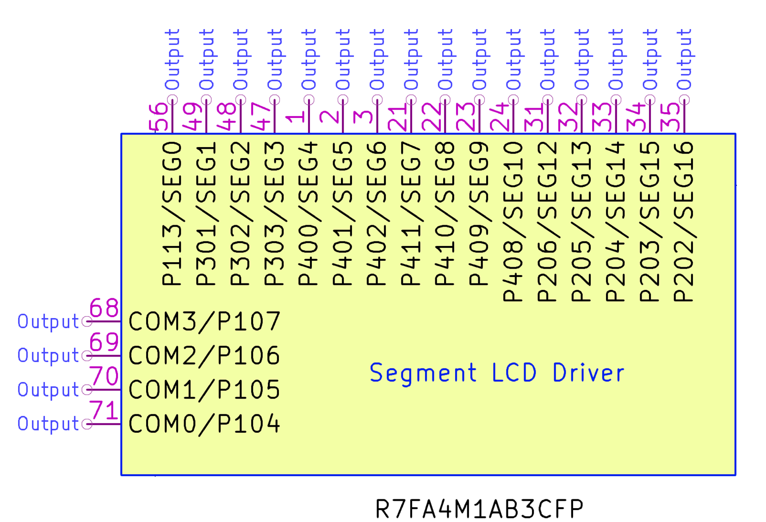
Here are the connection details for the GPIO pins configured for Segment LCD driver output for the TQFP 100-pin RA4M1 chip:

LCD Code
As with the previous blog post, an LCD bitmap array was created so that the code can translate ASCII characters into 7-segment output. Note that this time I’ve only checked the digits 0-9 since that's all I need, so there may be an error or two in the rest, but it would be a quick thing to fix. If you spot any errors, please let me know so I can correct them!
// LCD bitmap defines
#define IDX_NUM 0
#define IDX_ALPHA 10
#define IDX_HYPHEN 36
#define IDX_ROT 37

uint8_t char_bitmap[] = {
        0xbe, 0x06, 0x7c, 0x5e, 0xc6, 0xda, 0xfa, 0x0e, 0xfe, 0xde, /* 0-9 */
        0xee, 0xf2, 0xb8, 0x76, 0xf8, 0xe8, /*A-F*/
        0xb2, 0xe6, 0x02, 0x16, 0x00, 0xb0, 0x6a, 0x62, 0x72, /*G-O*/
        0xec, 0xce, 0x60, 0xda, 0xf0, 0x32, 0x00, 0x3a, /*P-W*/
        0x00, 0xd6, 0x00, /*X-Z*/
        0x40, /*-*/
        0x08, 0x04, 0x02, 0x10, 0x20, 0x80 /*rotation right from top*/
};
With this LCD screen, a single lcd_display function is insufficient because it may be desired to update the upper digits at a different rate to the lower digits. It may also be desired to independently control the signal and battery level bars. A single lcd_display function would be inconvenient.
Some definitions were created to simplify using all the various indicators on the display:
// LCD special indicator defines
// negative number indicator
#define NO_IND_NEG 0
#define IND_NEG 1
// percent sign indicator
#define NO_IND_PCT 0
#define IND_PCT 1
// degrees C indicator
#define NO_IND_DEGC 0
#define IND_DEGC 1
// battery icon
#define ICON_BATT 0
// signal level icon
#define ICON_SIGNAL 1
The following function, called lcd_display_4dig, is used to update the top digits.
void lcd_display_4dig(const char* char_data, uint8_t dp, uint8_t neg, uint8_t degc)
The function accepts a decimal point value (same as with the previous blog post) but now also accepts a negative value indicator, and a degC indicator. So, to display the text “-1.234” without a degC indicator, the code would be:
lcd_display_4dig(“1234”, 3, IND_NEG, NO_IND_DEGC);
Here is the entire function:
// global var:
uint8_t neg_indicator = 0;

// lcd_display_4dig accepts a 4-byte array char_data, and a decimal point indicator dp (0-3)
// and a negative value indicator neg (0-1) and a degc indicator (0-1)
// example to display the number -123.4 without a degC label:
//     uint8_t char_data[] = "1234";
//     lcd_display_4dig(char_data, 1, 1, 0);
void
lcd_display_4dig(const char* char_data, uint8_t dp, uint8_t neg, uint8_t degc) {
    fsp_err_t err;
    uint8_t i;
    uint8_t seg_data[17];
    uint8_t seg_idx;
    uint8_t seg_mask;
    for (i=0; i<17; i++) {
        seg_data[i] = 0;
    }
    for (i=0; i<4; i++) {
        seg_idx = i << 1;
        if ((char_data[i] >= '0') && (char_data[i] <= '9')) {
            seg_mask = char_bitmap[(char_data[i] - '0') + IDX_NUM];
        } else if ((char_data[i] >= 'A') && (char_data[i] <= 'Z')) {
            seg_mask = char_bitmap[(char_data[i] - 'A') + IDX_ALPHA];
        } else if (char_data[i] == '-') {
            seg_mask = char_bitmap[IDX_HYPHEN];
        } else if ((char_data[i] >= 'a') && (char_data[i] <= 'f')) {
            seg_mask = char_bitmap[(char_data[i] - 'a') + IDX_ROT];
        } else if (char_data[i] == ' ') {
            seg_mask = 0x00;
        } else { // unrecognized character
            seg_mask = char_bitmap[IDX_HYPHEN];
        }
        seg_data[seg_idx] = seg_mask >> 4;
        seg_data[seg_idx+1] = seg_mask & 0x0f;
    }
    switch(dp) {
        case 0:
            break;
        case 1:
            seg_data[5] |= 0x01;
            break;
        case 2:
            seg_data[2] |= 0x01;
            break;
        case 3:
            seg_data[1] |= 0x01;
            break;
        default:
            break;
    }
    if (neg) {
        neg_indicator = 1;
        err = R_SLCDC_Modify(&g_slcdc0_ctrl, 9, 0x01, 0x01);
        assert(FSP_SUCCESS == err);
    } else {
        neg_indicator = 0;
        err = R_SLCDC_Modify(&g_slcdc0_ctrl, 9, 0x00, 0x01);
        assert(FSP_SUCCESS == err);
    }
    if (degc)
        seg_data[7] |= 0x01;

    err = R_SLCDC_Write(&g_slcdc0_ctrl, 0, seg_data, 8);
    assert(FSP_SUCCESS == err);
}
In a similar vein, a function for the 3-digit display was created. If you can understand the 4-digit function, then this one is fairly self-explanatory. One difference between this function and the 4-digit one, is that a few segments need to be shifted in the array, because one of the segment GPIOs is not available on the RA4M1, because it clashes with the USB port. It is mentioned in the earlier blog post. This solution simply skips that segment GPIO, called P407 (SEG11) and uses an extra GPIO pin instead. This is easy enough, but it slightly complicates the code (not by much).
// lcd_display_3dig accepts a 3-byte array char_data, and a decimal point indicator dp (0-1)
// and a percent indicator (0-1)
// example to display the number 12.3 with no percent sign:
//     uint8_t char_data[] = "123";
//     lcd_display_3dig(char_data, 1, 0);
void
lcd_display_3dig(const char* char_data, uint8_t dp, uint8_t percent) {
    fsp_err_t err;
    uint8_t i;
    uint8_t seg_data[7];
    uint8_t seg_idx;
    uint8_t seg_mask;

    for (i=0; i<3; i++) {
        seg_idx = i << 1;
        if ((char_data[i] >= '0') && (char_data[i] <= '9')) {
            seg_mask = char_bitmap[(char_data[i] - '0') + IDX_NUM];
        } else if ((char_data[i] >= 'A') && (char_data[i] <= 'Z')) {
            seg_mask = char_bitmap[(char_data[i] - 'A') + IDX_ALPHA];
        } else if (char_data[i] == '-') {
            seg_mask = char_bitmap[IDX_HYPHEN];
        } else if ((char_data[i] >= 'a') && (char_data[i] <= 'f')) {
            seg_mask = char_bitmap[(char_data[i] - 'a') + IDX_ROT];
        } else if (char_data[i] == ' ') {
            seg_mask = 0x00;
        } else { // unrecognized character
            seg_mask = char_bitmap[IDX_HYPHEN];
        }
        seg_data[seg_idx] = seg_mask >> 4;
        seg_data[seg_idx+1] = seg_mask & 0x0f;
    }
    // shift the last three bytes because we are not using P407 (SEG11)
    seg_data[6] = seg_data[5];
    seg_data[5] = seg_data[4];
    seg_data[4] = seg_data[3];
    seg_data[3] = 0;
    if (dp)
        seg_data[4] |= 0x01;
    if (percent)
        seg_data[6] |= 0x01;
    if (neg_indicator) {
        seg_data[1] |= 0x01;
    }
    err = R_SLCDC_Write(&g_slcdc0_ctrl, 8, seg_data, 7);
    assert(FSP_SUCCESS == err);
}
Finally, a lcd_display_icon function was created to control the signal and battery level bars. The levels can be set between 0 and 4 (0 = no icon, 1 = lowest level, 4 = highest level).
For instance, to set the battery level indication to the maximum, use the code line:
lcd_display_icon(ICON_BATT, 4);
Here is the entire function:
// lcd_display_icon is used to set the battery level or signal level indicators
// usage: lcd_display_icon(ICON_BATT, 1); // 4 = max batt, 1= min batt, 0 = no batt icon
//        lcd_display_icon(ICON_SIGNAL, 4); // 4 = max signal, 1=min signal, 0 = no signal icon
void
lcd_display_icon(uint8_t icon, uint8_t val) {
    fsp_err_t err;
    uint8_t seg_data;
    switch (icon) {
        case ICON_SIGNAL:
            switch(val) {
                case 0:
                    seg_data = 0x00;
                    break;
                case 1:
                    seg_data = 0x08;
                    break;
                case 2:
                    seg_data = 0x0c;
                    break;
                case 3:
                    seg_data = 0x0e;
                    break;
                case 4:
                default:
                    seg_data = 0x0f;
                    break;
            }
            break;
        case ICON_BATT:
            switch(val) {
                case 0:
                    seg_data = 0x00;
                    break;
                case 1:
                    seg_data = 0x01;
                    break;
                case 2:
                    seg_data = 0x03;
                    break;
                case 3:
                    seg_data = 0x07;
                    break;
                case 4:
                default:
                    seg_data = 0x0f;
                    break;
            }
            break;
        default:
            break;
    }
    err = R_SLCDC_Write(&g_slcdc0_ctrl, icon+15, &seg_data, 1);
    assert(FSP_SUCCESS == err);
}
Summary
It’s fairly straightforward to add larger segment LCD screens to the Renesas RA family microcontrollers. The code allows for independent control of the two groups of digits, and the battery and signal strength level displays.
Since there are lots of wires connected to the LCD (20 pins), it would be worthwhile creating a circuit board.
Thanks for reading!
