element14 Community
element14 Community
    Register Log In
  • Site
  • Search
  • Log In Register
  • Community Hub
    Community Hub
    • What's New on element14
    • Feedback and Support
    • Benefits of Membership
    • Personal Blogs
    • Members Area
    • Achievement Levels
  • Learn
    Learn
    • Ask an Expert
    • eBooks
    • element14 presents
    • Learning Center
    • Tech Spotlight
    • STEM Academy
    • Webinars, Training and Events
    • Learning Groups
  • Technologies
    Technologies
    • 3D Printing
    • FPGA
    • Industrial Automation
    • Internet of Things
    • Power & Energy
    • Sensors
    • Technology Groups
  • Challenges & Projects
    Challenges & Projects
    • Design Challenges
    • element14 presents Projects
    • Project14
    • Arduino Projects
    • Raspberry Pi Projects
    • Project Groups
  • Products
    Products
    • Arduino
    • Avnet Boards Community
    • Dev Tools
    • Manufacturers
    • Multicomp Pro
    • Product Groups
    • Raspberry Pi
    • RoadTests & Reviews
  • Store
    Store
    • Visit Your Store
    • Choose another store...
      • Europe
      •  Austria (German)
      •  Belgium (Dutch, French)
      •  Bulgaria (Bulgarian)
      •  Czech Republic (Czech)
      •  Denmark (Danish)
      •  Estonia (Estonian)
      •  Finland (Finnish)
      •  France (French)
      •  Germany (German)
      •  Hungary (Hungarian)
      •  Ireland
      •  Israel
      •  Italy (Italian)
      •  Latvia (Latvian)
      •  
      •  Lithuania (Lithuanian)
      •  Netherlands (Dutch)
      •  Norway (Norwegian)
      •  Poland (Polish)
      •  Portugal (Portuguese)
      •  Romania (Romanian)
      •  Russia (Russian)
      •  Slovakia (Slovak)
      •  Slovenia (Slovenian)
      •  Spain (Spanish)
      •  Sweden (Swedish)
      •  Switzerland(German, French)
      •  Turkey (Turkish)
      •  United Kingdom
      • Asia Pacific
      •  Australia
      •  China
      •  Hong Kong
      •  India
      •  Korea (Korean)
      •  Malaysia
      •  New Zealand
      •  Philippines
      •  Singapore
      •  Taiwan
      •  Thailand (Thai)
      • Americas
      •  Brazil (Portuguese)
      •  Canada
      •  Mexico (Spanish)
      •  United States
      Can't find the country/region you're looking for? Visit our export site or find a local distributor.
  • Translate
  • Profile
  • Settings
Embedded and Microcontrollers
  • Technologies
  • More
Embedded and Microcontrollers
Blog ESP32 I2C programming tutorial with ESP-IDF
  • Blog
  • Forum
  • Documents
  • Quiz
  • Polls
  • Files
  • Members
  • Mentions
  • Sub-Groups
  • Tags
  • More
  • Cancel
  • New
Join Embedded and Microcontrollers to participate - click to join for free!
  • Share
  • More
  • Cancel
Group Actions
  • Group RSS
  • More
  • Cancel
Engagement
  • Author Author: embeddedguy
  • Date Created: 2 Jun 2025 11:44 AM Date Created
  • Views 455 views
  • Likes 7 likes
  • Comments 5 comments
  • esp32
  • embedded
Related
Recommended

ESP32 I2C programming tutorial with ESP-IDF

embeddedguy
embeddedguy
2 Jun 2025

Table of Contents

  • Blog List
    • Introduction to I2C hardware
    • I2C API in ESP-IDF
    • Programming sequence
    • References

Blog List

ESP32 UART tutorial

ESP32 ADC tutorial

Some time ago I wrote two blogs about programming ESP32 devices. One of them was about using ADC (Analog to Digital converters) and another was using UART (Universal Asynchronous Receiver Transmitter) peripheral. These peripherals were simple in terms of complexity. They are very basic peripherals. In this tutorial I am going to write about I2C (Inter integrated Circuit) peripheral in ESP32 devices. 

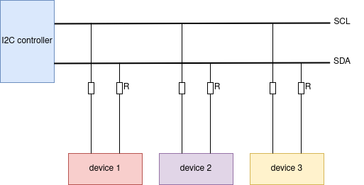
I2C is simple and one of the quite commonly used protocol for data transfer between master and slave devices. The I2C is two wire interface, namely SCL (Serial Clock Line) for clock signal and SDA (Serial Data Line) for transferring data. Each I2C device has 7-bit address assigned to them. 

Introduction to I2C hardware

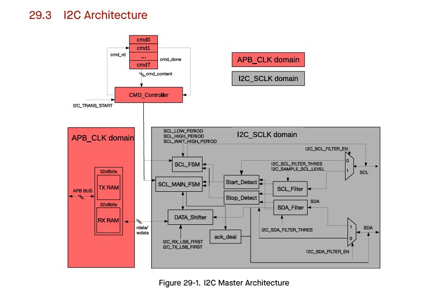
Before going deep into the working of I2C, let's have a look at the I2C hardware block in ESP32 devices. The ESP32 series of devices have dedicated hardware block for I2C peripheral. These peripherals are divided into master and slave blocks. In this tutorial the focus is on ESP32 as master devices only. As you could see in the following block diagram of I2C peripheral there are several things in the peripheral block. One of them is command controller that controls the I2C device commands. These commands are then sent over the I2C bus. The FSM (Finite state machine) will fetch these commands from the list and send them over to the bus. Similarly as you could see in the following block, there is start/stop detector, data shifter, and acknowledge detector. The block has 32x8 bits of separate memory for TX and RX data that can store the data from the transmit and receive operations. 

image

I2C API in ESP-IDF

The I2C API in ESP-IDF is designed to work with master/slave I2C device function. The ESP32 can act as master, or it can act as slave to other master such as other SoC or microrontroller. The most commonly used function is I2C master. In this the ESP32 device will communicate with other slave device such as sensors based on I2C protocol. The figure below shows the wiring between the master (controller) and the slave (device) functions. Sometimes pull-up resistors are required to pull the device line status up by default if the peripheral lines are not in use. The ESP32 has internal pull-ups that can be enabled in software to avoid external pull-ups. 

image

The following figure shows the sequence of data transfer between the master and slave devices. The master sends the start condition plus device address and write-bit to initiate the communication with slave device. The device responds with data that was requested. At the end an ACK and stop bits are sent.

image

Programming sequence

The programming sequence requires the respective API to be enabled in the CmakeList.txt file. Include the following lines in the CMakeList.txt file to enable the API.

                                        PRIV_REQUIRES esp_driver_i2c
                    PRIV_REQUIRES esp_driver_ledc
                    PRIV_REQUIRES esp_driver_gpio  
After that include the required header files in the main.c
#include "driver/i2c_master.h"
#include "driver/ledc.h"
For this tutorial I have create a simple I2C scanner that can scan available I2C slave devices on the I2C bus. I am using a camera module that has OV-2640 camera module that uses SCCB interface compatible with I2C communication. 
image
The SCCB interface requires some extra pins for functioning. Such as MCLK, Reset, PCLK. The MCLK is a master clock and can be supplied with clock of 24 MhZ. For that reason, I am using LEDC (PWM) interface available in ESP-IDF. This will create the required signal on MCLK pin.
Then the I2C will be able to find the camera module on the I2C bus. The camera has the device address of 0x30 and as you could see from the output console that the I2C probe function finds the device on that particular address.!
The I2C requires some configuration parameters to work. The API has i2c_master_bus_config_t structure that can be configured to I2C I/O pins and parameters as shown in the following code snippet. 
 
 i2c_master_bus_config_t i2c_mst_config = {
    .clk_source = I2C_CLK_SRC_DEFAULT,
    .i2c_port = -1,
    .scl_io_num = 39,
    .sda_io_num = 40,
    .glitch_ignore_cnt = 7,
    .flags.enable_internal_pullup = true,
   
    };

i2c_master_bus_handle_t bus_handle;
i2c_new_master_bus(&i2c_mst_config, &bus_handle);
/*
 * SPDX-FileCopyrightText: 2010-2022 Espressif Systems (Shanghai) CO LTD
 *
 * SPDX-License-Identifier: CC0-1.0
 */

#include <stdio.h>
#include <inttypes.h>
#include "sdkconfig.h"
#include "freertos/FreeRTOS.h"
#include "freertos/task.h"
#include "esp_chip_info.h"
#include "esp_flash.h"
#include "esp_system.h"
#include "driver/i2c_master.h"
#include "driver/ledc.h"

#include "esp_log.h"

void app_main(void)
{
    int ret;
    printf("Hello world!\n");

    ledc_timer_config_t ledc_timer = {
        .speed_mode = LEDC_LOW_SPEED_MODE,
        .duty_resolution = LEDC_TIMER_1_BIT,
        .timer_num = LEDC_TIMER_0,
        .freq_hz = 24000000,
        .clk_cfg = LEDC_AUTO_CLK
    };

    ledc_timer_config(&ledc_timer);

    ledc_channel_config_t ledc_channel = {
        .speed_mode = LEDC_LOW_SPEED_MODE,
        .channel = LEDC_CHANNEL_0,
        .timer_sel = LEDC_TIMER_0,
        .intr_type = LEDC_INTR_DISABLE,
        .gpio_num = 10,
        .duty = 1,
        .hpoint = 0,
    };

    ledc_channel_config(&ledc_channel);

    i2c_master_bus_config_t i2c_mst_config = {
    .clk_source = I2C_CLK_SRC_DEFAULT,
    .i2c_port = -1,
    .scl_io_num = 39,
    .sda_io_num = 40,
    .glitch_ignore_cnt = 7,
    .flags.enable_internal_pullup = true,
   
    };

i2c_master_bus_handle_t bus_handle;
i2c_new_master_bus(&i2c_mst_config, &bus_handle);

i2c_master_dev_handle_t dev_handle;

while (1)
{
    uint8_t slave = 0x00;
    printf("Start\n");

    for(int i = 0; i<=127; i++) {
        ret = i2c_master_probe(bus_handle, slave, -1);
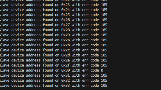
        printf("slave device address found on 0x%x with err code %x\n", slave, ret);
        vTaskDelay(50);
        slave = slave + 1;
    }    
}
}
image

References

1> ESP32 technical reference manual

2> ESP-IDF documentation

  • Sign in to reply

Top Comments

  • michaelkellett
    michaelkellett 11 days ago in reply to embeddedguy +1
    I had a quick look at their documentation and it certainly leaves quite a lot to be desired in the brief description of I2C hardware. You need to take care with putting resistors between I2C devices…
  • michaelkellett
    michaelkellett 10 days ago in reply to embeddedguy

    Hello,

    I may be wrong here because the Espressif Data sheet is a bit lacking and the information I found on the web is quite old but it looks as if the I2C relies on the standard GPIO internal week pullups which are any where between 10k and 100k.

    This will not provide good I2C compatibility.

    The snippets below from the ESP forum suggest that Espressif recommend the use of external pull ups.

    Large variations in chip internal pull up resistor values are normal.

    You should be looking for an RC time constant of about 1us (rough estimate see the I2C spec for details) so with a 100k pull up the maximum capacitance that can be tolerated is of the order of 10pF. 

    The first chip I checked claims a maximum pin capacitance of 10pF so you would expect an interface between 2 chips or even 3 to work at 100kHz rate with a typical internal pull up if all three chips were 10pF.

    With the generally recommended 4k7 pull up you would be 100% confident.

    Resistors are cheap - debugging time is expensive and pcb re-work costs horrendous and there is the added bonus that the pull up resistors make good places to attach probes for when you need to look at the I2C bus with a scope or logic analyser.

    MK

    image

    image

    • Cancel
    • Vote Up 0 Vote Down
    • Sign in to reply
    • More
    • Cancel
  • embeddedguy
    embeddedguy 11 days ago in reply to michaelkellett

    Device Pull-ups are essential but in my case the sensors that I used have it. So no need to have extra wiring. Also the for Pull-ups there are common values ranging from 4.7K to 10K means the internal resistors should be near to that value. Still, if there is issue in I2C communication one can use appropriate external resistors to get the bus to right working state. 

    From the experience that I have so far with I2C these external resistors are rarely needed. 

    UR

    • Cancel
    • Vote Up 0 Vote Down
    • Sign in to reply
    • More
    • Cancel
  • michaelkellett
    michaelkellett 11 days ago in reply to embeddedguy

    I had a quick look at their documentation and it certainly leaves quite a lot to be desired in the brief description of I2C hardware. 

    You need to take care with putting resistors between I2C devices and the bus and it is not common to do so.

    The Technical Reference Manual is better but its probably easier to understand I2C by reading the Bus Specification (you still need the Technical Reference to understand the chip !) 

    www.nxp.com/.../UM10204.pdf

    Pull up devices are essential.

    Ideally they should be tuned to optimise performance (as the ESP-IDF doc mentions but then fails to tell you about the built in ones or their value.)

    MK

    • Cancel
    • Vote Up +1 Vote Down
    • Sign in to reply
    • More
    • Cancel
  • embeddedguy
    embeddedguy 11 days ago in reply to michaelkellett

    I have just copied that image from ESP-IDF documentation. I think they show this for the resistance faced by signals from the wire of I2C.

    • Cancel
    • Vote Up 0 Vote Down
    • Sign in to reply
    • More
    • Cancel
  • michaelkellett
    michaelkellett 11 days ago

    Why are you showing resistors in the signal lines to the I2C devices in your diagram. ?

    MK

    • Cancel
    • Vote Up 0 Vote Down
    • Sign in to reply
    • More
    • Cancel
element14 Community

element14 is the first online community specifically for engineers. Connect with your peers and get expert answers to your questions.

  • Members
  • Learn
  • Technologies
  • Challenges & Projects
  • Products
  • Store
  • About Us
  • Feedback & Support
  • FAQs
  • Terms of Use
  • Privacy Policy
  • Legal and Copyright Notices
  • Sitemap
  • Cookies

An Avnet Company © 2025 Premier Farnell Limited. All Rights Reserved.

Premier Farnell Ltd, registered in England and Wales (no 00876412), registered office: Farnell House, Forge Lane, Leeds LS12 2NE.

ICP 备案号 10220084.

Follow element14

  • X
  • Facebook
  • linkedin
  • YouTube