


Recently, I started making pour-over coffee at home, and it turns out that water temperature can change the taste a lot. I don’t have a kettle that can measure temperature, so time to make something.
I found a few DS18B20s with stainless steel housing and a long cable, which are perfect for this purpose. Initially, I just used an Arduino Uno with a TFT display shield, but it was quite janky, and also needed USB power to run.
So here’s the plan:
- 18650 cell for power
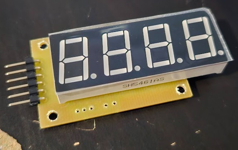
- 4 digit 7 segment displays
- USB-C charging
- 3D printed housing
Schematics and PCB
I didn’t want to wait a week for PCBs, so I decided to use my 3D printer, which I modified to be able to hold a 48V spindle motor. To make this more interesting, I decided to limit myself to using a single layer PCB design, and an ATTINY AVR microcontroller.
I chose the ATTINY24A, and a MAX7219 for driving the display. The ATTINY needs 1.8V to 5.5V, while the MAX7219 requires 4V to 5.5V, but I found that it works down to about 3V without any issues. This means I do not need a voltage regulator and can run everything straight off the 18650(~3.5V to 4.2V).

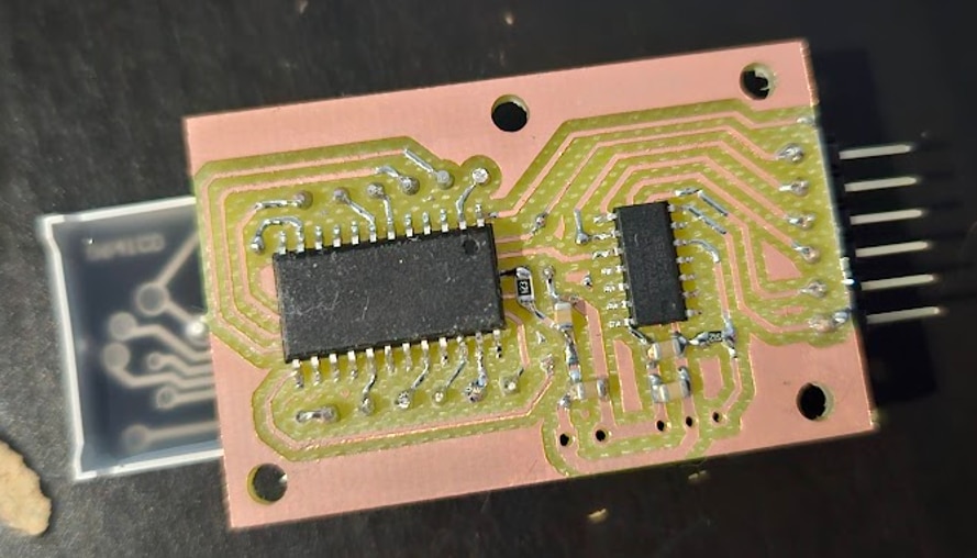
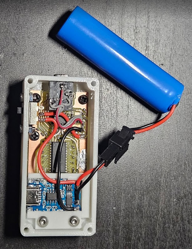
Originally I had the MAX7219 share the SCK/MISO pins with the ICSP header, and also forgot the RST pullup, but didn’t make a new PCB with these changes, just cut the traces and hooked up some bodge wires, visible in later photos. The original version would’ve worked too, but having separate pins helped with debugging, and had plenty of unused GPIOs on the AVR anyways.
Here’s the original layout that I ended up milling:
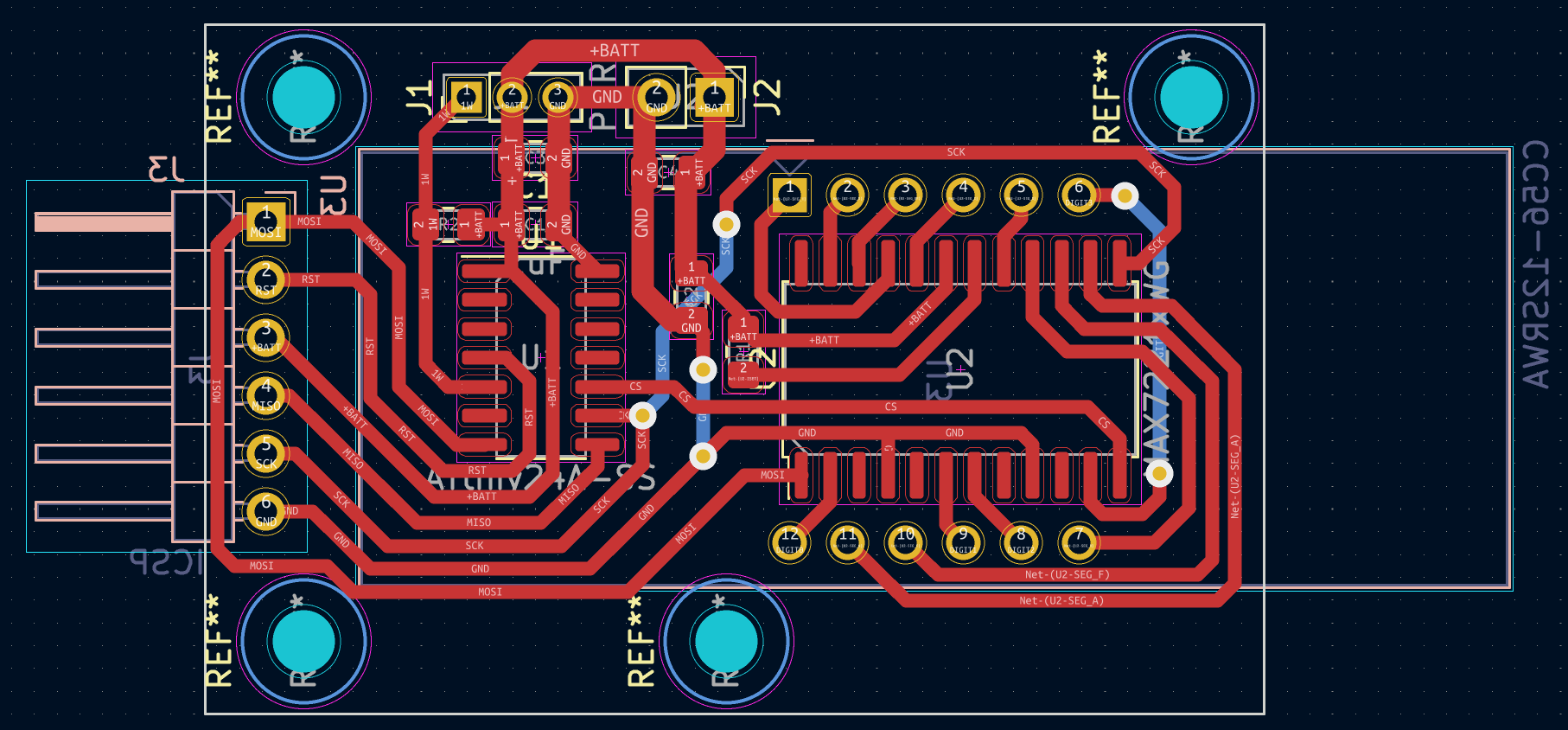
In the end, I needed 3 through-hole jumpers, shown as the back layer with blue in the layout.
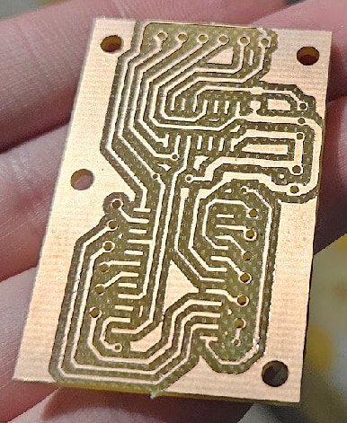
This was one of the first PCBs I milled, didn’t have everything figured out yet, so it’s not the best looking, with a lot of the traces ending up thinner than they should be. They all made proper electrical contact though, so good enough for this purpose.
AVR code
Controlling the MAX7219 was quite easy, just need to send out two bytes on MOSI, the first being register address, and the second is the value to write.
#define CS 3
#define MOSI 2
#define SCK 1

void set(uint8_t pin, uint8_t val) {
	if (val == 0) {
		PORTA &= ~(1 << pin);
	}
	else {
		PORTA |= (1 << pin);
	}
}

void shiftOut(uint8_t data) {
	for(uint8_t i = 0; i < 8; i++) {
		int bit = data & (1 << (7-i));
		set(MOSI, bit);

		_delay_us(1);
		set(SCK, 1);
		_delay_us(1);
		set(SCK, 0);
	}
}

void setMAXRegister(uint8_t reg, uint8_t value) {
	set(CS, 0);
	_delay_us(1);
	shiftOut(reg);
	shiftOut(value);
	_delay_us(1);
	set(CS, 1);
	_delay_us(1);
}
To set up the MAX7219, I had to disable shutdown mode, disable “Display Test mode”, enable “Code B decode for digits 0-3”, set the brightness, and enable the first 4 displays only:
setMAXRegister(0x0C, 1);	// Shutdown -> Normal mode
setMAXRegister(0x0F, 0);	// Display Test -> Normal mode
setMAXRegister(0x09, 0x0F);	// Decode Mode -> Code B decode for digits 0-3
setMAXRegister(0x0A, 0);	// Intensity -> 0
setMAXRegister(0x0B, 3);	// Scan Limit -> 0,1,2,3
Displaying digits was simple as well, the MAX7219 can figure out on its own what segments to power on, all I needed to do was put the number I wanted to display in a register.
void setMAXDigit(uint8_t digit, uint8_t val, bool dot) {
	uint8_t lookup[] = {0, 2, 3, 1};
	uint8_t dig = lookup[digit];
	if (dot == true) {
		val |= (1 << 7);
	}
	setMAXRegister(dig+1, val);
}
The lookup array is needed, because I didn’t connect the 7 segment displays in order, due to layout constraints on the PCB.
For reading temperature from the DS18B20, I ended up slightly modifying a library I found on GitHub(https://github.com/Jacajack/avr-ds18b20), mostly just removing parts I didn’t need.
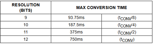
First, I set the DS18B20 to 11bit resolution (0.125C per count), which I found to be a good compromise between readout rate and precision:
ds18b20wsp(&PORTB, &DDRB, &PINB, ( 1 << 2 ), 0, 0, 125, DS18B20_RES11);
Then all I had to do was tell the DS18B20 to start a conversion, and then read the result.
int16_t temp = 0;
ds18b20convert(&PORTB, &DDRB, &PINB, ( 1 << 2 ), 0);
_delay_ms(10);
ds18b20read(&PORTB, &DDRB, &PINB, ( 1 << 2 ), 0, &temp);
The library returns the temperature multiplied by 16, to avoid having to use floats/doubles(the highest resolution 12-bit mode has a resolution of 0.0625C, which is 1/16th C).
To display this number properly, I wrote the following function:
void setMAXfromDS(int16_t dstemp) {
	if(dstemp >= 0) {
		uint16_t temp_integer = dstemp / 16;
		if(dstemp < 100*16) { // Under 100C
			uint16_t temp_fraction = ((dstemp % 16) * 100) / 16;

			setMAXDigit(0, temp_integer / 10, false);
			setMAXDigit(1, temp_integer % 10, true);
			setMAXDigit(2, temp_fraction / 10, false);
			setMAXDigit(3, temp_fraction % 10, false);
		}
		else { // Over 100C
			uint16_t temp_fraction = ((dstemp % 16) * 10) / 16;

			setMAXDigit(0, temp_integer / 100, false);
			temp_integer = temp_integer % 100;
			setMAXDigit(1, temp_integer / 10, false);
			setMAXDigit(2, temp_integer % 10, true);
			setMAXDigit(3, temp_fraction, false);
		}
	}
	else {
		//TODO - negative temp handling
	}
}
Temperatures at or over 100C are displayed with one decimal point of accuracy, between 0-100 two decimal points are used. I haven’t implemented negative temperature handling yet, as I have no need for it currently.
I also wanted some way to measure battery voltage and display it at startup. The straightforward solution, which would be to connect the battery to an ADC pin, wouldn’t work without an external reference, which would also need to be at least 4.2V to work properly.
The solution is to not connect the battery to an ADC pin at all, but use the ADC to measure an internal 1.1V reference instead, with the ADC reference set to Vcc. Here’s an example how this would work:
The ADC is 10-bit, meaning 0-1023. Let’s assume Vcc=2.2V, and we know that the internal reference is 1.1V. This means the ADC will read 512, since the internal reference(1.1V) is exactly half the voltage of the ADC reference(Vcc). (Vcc/1.1V = 1024/ADC_counts)
The internal reference isn’t exactly 1.1V though, so first step is to figure out the exact value. By measuring Vcc externally with a multimeter, and taking an ADC measurement, we can calculate the accurate value using this formula: measured_vcc * ADC_counts / 1024. In my case, I got 1.0906875V.
Knowing this, Vcc can be calculated like so: 1.0906875V * 1024 / ADC_counts. To avoid having to deal with floats here too, I further multiplied this value by 1000, to end up with 3 decimal points of accuracy in the end. Since Vcc will always be a number between 1.8V(hopefully more like 3.5V) and 4.2V, I can always assume the decimal point is after the first digit(that’s what the “true” in the first “setMAXDigit” function call is). The formula now simplifies to 1116860 / ADC_counts.
Accuracy is within 0.05V compared to what my multimeter measures, so I’m pleasantly surprised with how well this works, although I haven’t tested how much the reference drifts with ambient temperature change.
void showVccVoltage(uint16_t adcval) {
	// Bandgap voltage: (actualVcc * adcReading) / 1024
	// Vcc: (bandgapVoltage * 1024) / adcReading

	uint16_t num = 1116860 / adcval; // Multiplied by 1000 to not have to deal with floats

	setMAXDigit(0, num / 1000, true);
	num = num % 1000;
	setMAXDigit(1, num / 100, false);
	num = num % 100;
	setMAXDigit(2, num / 10, false);
	setMAXDigit(3, num % 10, false);
}

ADMUX = 0b00100001; // Vcc as reference, measuring 1.1V internal bandgap
ADCSRA = 0b10000100; // Enable ADC, prescaler 16

ADCSRA |= (1 << ADSC); // Start conversion
while(!(ADCSRA & (1 << ADIF))); // Wait for conversion to complete
ADCSRA |= (1 << ADIF); // Clear the ADC interrupt flag
volatile uint16_t adcl = ADCL; // Read lower byte
uint16_t value = (((uint16_t)ADCH) << 8) | adcl; // Read upper byte and merge into uint16_t
showVccVoltage(value);
Here's the entire code:
#include <avr/io.h>
#include <util/delay.h>
#include <stdbool.h>
#include "ds18b20.h"

#define CS 3
#define MOSI 2
#define SCK 1

void set(uint8_t pin, uint8_t val) {
	if (val == 0) {
		PORTA &= ~(1 << pin);
	}
	else {
		PORTA |= (1 << pin);
	}
}

void shiftOut(uint8_t data) {
	for(uint8_t i = 0; i < 8; i++) {
		int bit = data & (1 << (7-i));
		set(MOSI, bit);

		_delay_us(1);
		set(SCK, 1);
		_delay_us(1);
		set(SCK, 0);
	}
}

void setMAXRegister(uint8_t reg, uint8_t value) {
	set(CS, 0);
	_delay_us(1);
	shiftOut(reg);
	shiftOut(value);
	_delay_us(1);
	set(CS, 1);
	_delay_us(1);
}

void setMAXDigit(uint8_t digit, uint8_t val, bool dot) {
	uint8_t lookup[] = {0, 2, 3, 1};
	uint8_t dig = lookup[digit];
	if (dot == true) {
		val |= (1 << 7);
	}
	setMAXRegister(dig+1, val);
}

void showVccVoltage(uint16_t adcval) {
	// Bandgap voltage: (actualVcc * adcReading) / 1024
	// Vcc: (bandgapVoltage * 1024) / adcReading

	uint16_t num = 1116860 / adcval; // Multiplied by 1000 to not have to deal with floats

	setMAXDigit(0, num / 1000, true);
	num = num % 1000;
	setMAXDigit(1, num / 100, false);
	num = num % 100;
	setMAXDigit(2, num / 10, false);
	setMAXDigit(3, num % 10, false);
}

void setMAXfromDS(int16_t dstemp) {
	if(dstemp >= 0) {
		uint16_t temp_integer = dstemp / 16;
		if(dstemp < 100*16) { // Under 100C
			uint16_t temp_fraction = ((dstemp % 16) * 100) / 16;

			setMAXDigit(0, temp_integer / 10, false);
			setMAXDigit(1, temp_integer % 10, true);
			setMAXDigit(2, temp_fraction / 10, false);
			setMAXDigit(3, temp_fraction % 10, false);
		}
		else { // Over 100C
			uint16_t temp_fraction = ((dstemp % 16) * 10) / 16;

			setMAXDigit(0, temp_integer / 100, false);
			temp_integer = temp_integer % 100;
			setMAXDigit(1, temp_integer / 10, false);
			setMAXDigit(2, temp_integer % 10, true);
			setMAXDigit(3, temp_fraction, false);
		}
	}
	else {
		//TODO - negative temp handling
	}
}

int main(void) {
	_delay_ms(500);

	// Set pins as output
	DDRA |= (1 << CS);
	DDRA |= (1 << SCK);
	DDRA |= (1 << MOSI);

	set(CS, 1);
	set(SCK, 0);
	set(MOSI, 0);

	ADMUX = 0b00100001; // Vcc as reference, measuring 1.1V internal bandgap
	ADCSRA = 0b10000100; // Enable ADC, prescaler 16
	_delay_ms(1);

	setMAXRegister(0x0C, 1);	// Shutdown -> Normal mode
	setMAXRegister(0x0F, 0);	// Display Test -> Normal mode
	setMAXRegister(0x09, 0x0F);	// Decode Mode -> Code B decode for digits 0-3
	setMAXRegister(0x0A, 0);	// Intensity -> 0
	setMAXRegister(0x0B, 3);	// Scan Limit -> 0,1,2,3
	_delay_ms(200);

	ds18b20wsp(&PORTB, &DDRB, &PINB, ( 1 << 2 ), 0, 0, 125, DS18B20_RES11); // Set DS18B20 to 11bit resolution mode

	// Display battery voltage for about 3 seconds (displays 30 values, each taking 100ms to calculate)
	for(uint8_t j = 0; j < 30; j++) {
		// Take an average of 100 ADC readings
		uint16_t adcsum = 0;
		for(uint8_t i = 0; i < 100; i++) {
			ADCSRA |= (1 << ADSC); // Start conversion
			while(!(ADCSRA & (1 << ADIF))); // Wait for conversion to complete
			ADCSRA |= (1 << ADIF); // Clear the ADC interrupt flag
			volatile uint16_t adcl = ADCL; // Read lower byte
			adcsum += (((uint16_t)ADCH) << 8) | adcl; // Read upper byte and merge into uint16_t, add to sum
			_delay_ms(1);
		}
		// Show the averaged voltage
		showVccVoltage(adcsum / 100);
	}

	int16_t temp = 0;
	while (1) {
		// Start DS18B20 conversion
		ds18b20convert(&PORTB, &DDRB, &PINB, ( 1 << 2 ), 0);
		_delay_ms(10);
		// Fetch result
		ds18b20read(&PORTB, &DDRB, &PINB, ( 1 << 2 ), 0, &temp);
		// Display result
		setMAXfromDS(temp);
	}

	return 0;
}
Housing
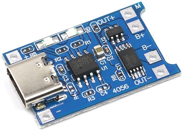
I found a TP4056 and DW01 based USB-C charger and protection board to use, but it didn’t have any mounting holes:
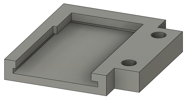
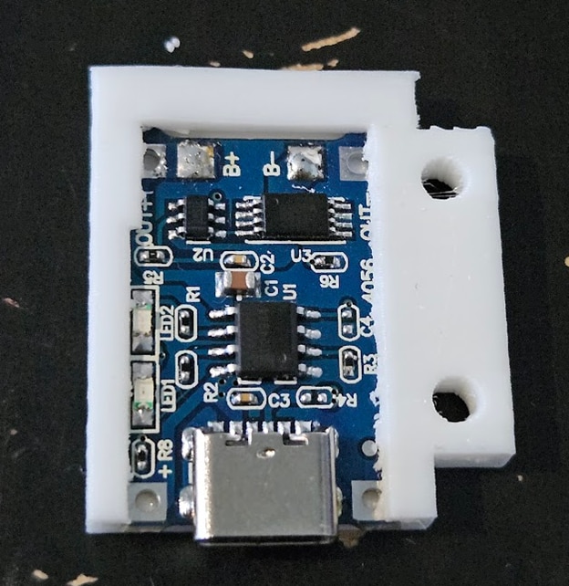
To simplify the housing design, I made a small plastic holder that the module can slide into, and has two holes on the side for screws:
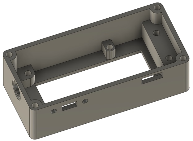
I will use a simple slide switch for turning the power on and off, and a 3.5mm audio jack to connect the DS18B20. Here’s the top part of the case:
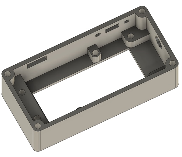


The other half of the case only has to fit the round 18650 cell, so I made the top and bottom angled, and the back curved:


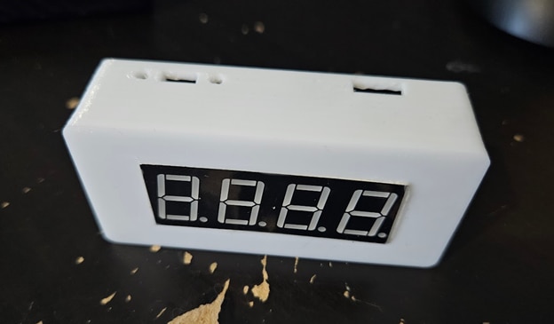
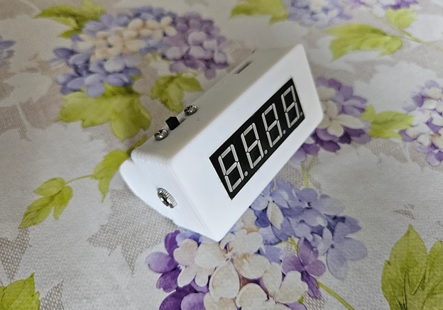
Finished device

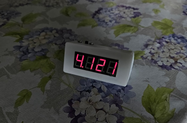
Showing battery voltage on startup, for about 3 seconds:
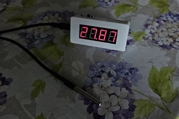
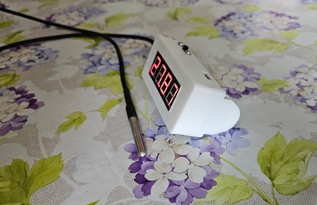
And measuring temperature:
Top Comments