


|
I was evaluating the Renesas RX65N MCU EV Kit a few years ago. While doing my road tests, the LCD screen died*. Andrew J sent me his screen (and his EV kit!). I can now investigate the latest RX65N - Segger emWin tool chain. In this post: I collect all info that got me to a working minimal viable product, with the GCC toolchain.
Documentation captures are from Renesas public releases. I link to the source. Fair use doctrine. |
I haven't cleaned up this post. I don't know yet what info is important. It 'll be rendered into a manual once I know what's working correctly.
Current state: all sections are ready, except the last one: Software Configuration.
Evaluation Kit specifics
I've captured the LCD specific settings in Renesas RX65 Envision Kit - Display Configuration for EastRising 5" TFT LCD display . I didn't document the capacitive touchscreen setup in that post. Below is the info related to the screen of the Evasion kit:
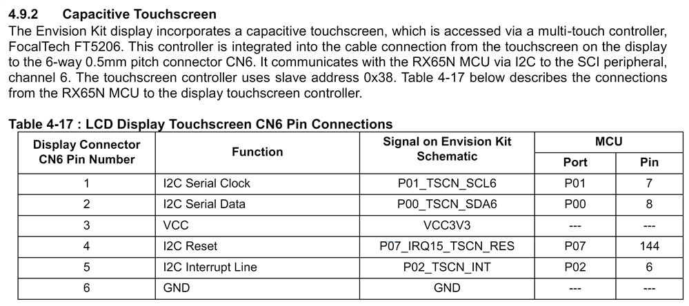
https://www.renesas.com/us/en/document/mat/rx65n-envision-kit-users-manual-rev100
emWin toolchain
The emWin layer has changed since Road Test times.
- The GUI design application is called AppWizard. Until version 6, it was GUIBuilder.
- Renesas' Eclipse plug-in QE for Display walks to all the steps from FIT block selection and configuration, up to installation of AppWizard and priming the GUI project for you.
Majority of the settings are derived from the Renesas board definition file in Eclipse, and from a board definition file that's part of the AppWizard install.
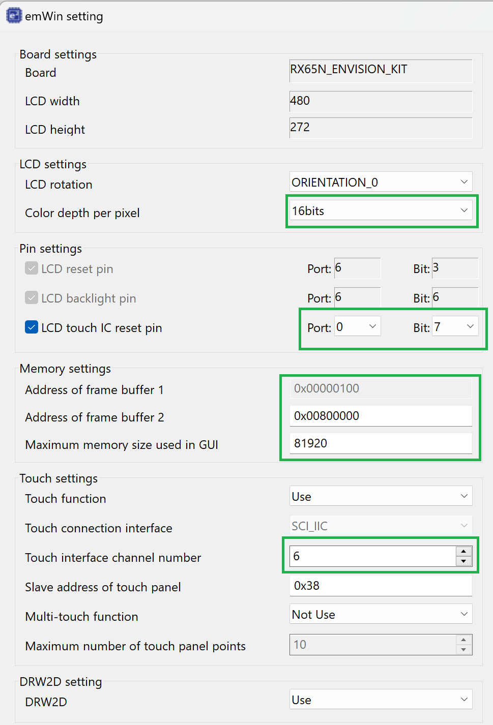
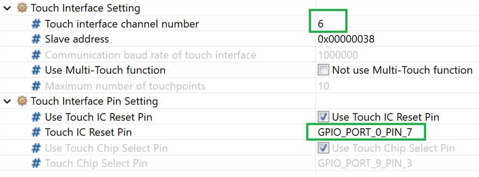
Following the QE plug-in steps doesn't result in a working example. I have to manually correct a few things: The Touch IC reset is not the correct pin (should be P07). Memory buffer addresses, at least on GCC, seem to be are wrong for this processor. I still have to find out a buffer and linker file definition that gives a full image on the display.
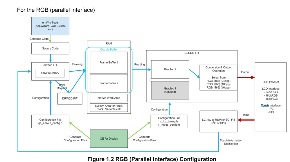
Below is a diagram that shows how the software stack works together, specific for the colour depth that I'm using.
Frame Buffer Configuration
This is the part where I don't have a correct setup yet.
The RX65N memory is split in RAM and extended RAM. Both chunks are not big enough to contain both frame buffers. Careful memory layout is required. emWin works best with 3 buffers, but that's not possible with the available RAM. Two buffers is a working compromise.
Sizing of the two frame buffers:
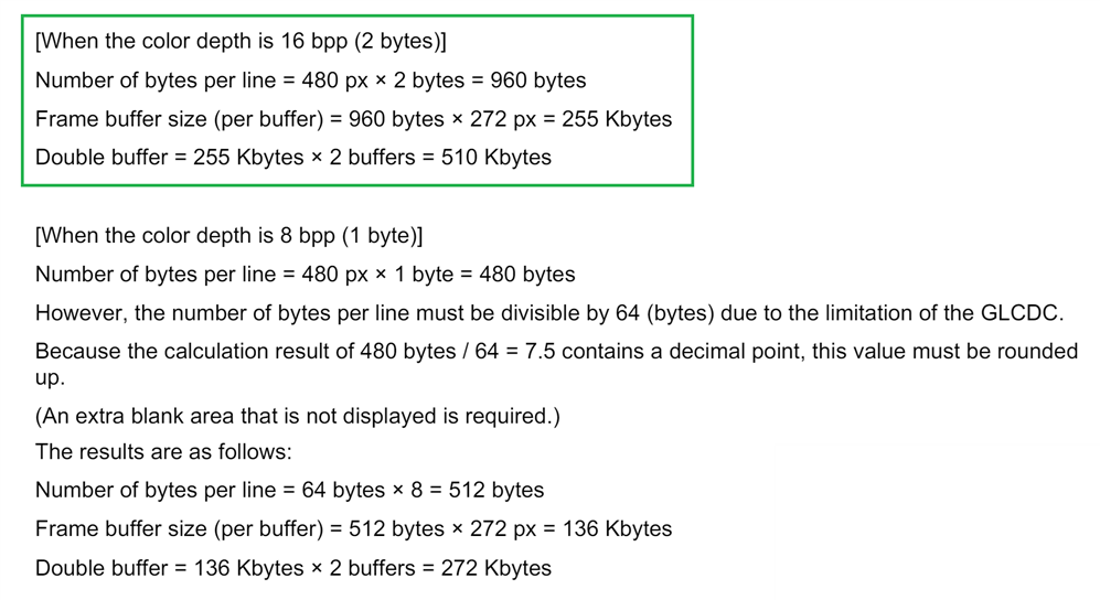
I'm using 16 bits per pixel (bpp) colour depth.
Available RAM areas for the Renesas controllers that have an LCD driver below. The RX65N specs are on the first row, and the layout in the diagram on the left.
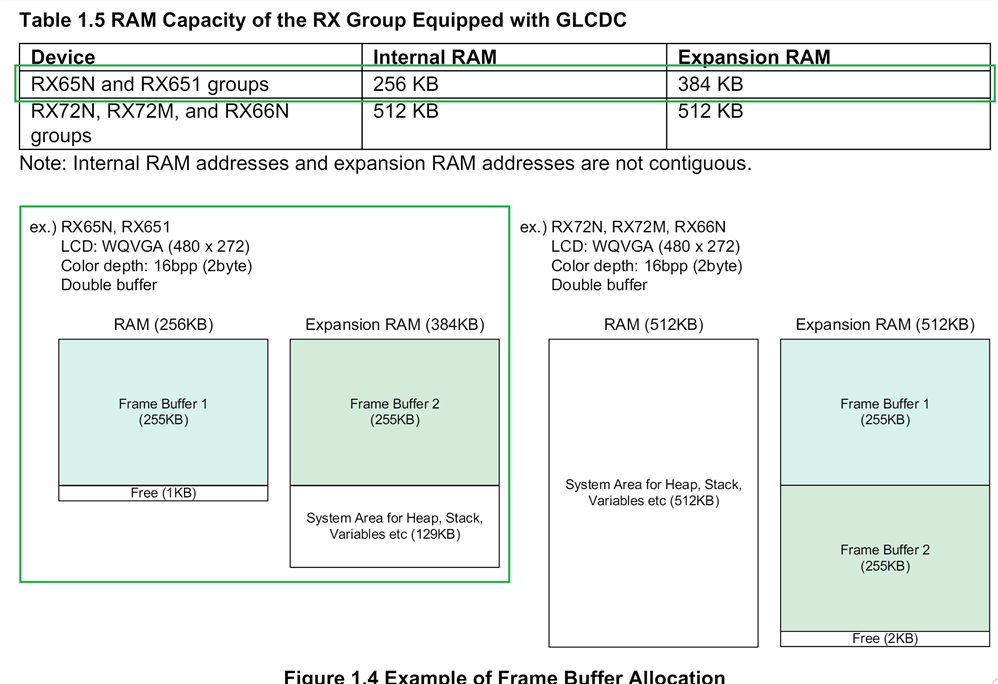
The 2 RAM areas can each contain one buffer with 16 bpp. They are physically distinct RAM blocks:
source: https://www.renesas.com/us/en/document/dst/rx65n-group-rx651-group-datasheet
The addresses are not contiguous:
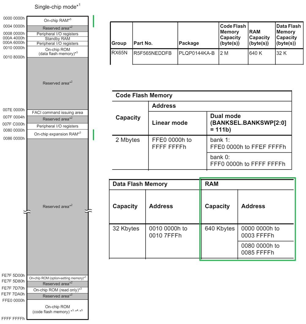
source: https://www.renesas.com/us/en/document/dst/rx65n-group-rx651-group-datasheet
|
settings of an older project, using the emWin GUIBuilder: Display: #define COLOR_CONVERSION GUICC_M565
#define NUM_BUFFERS 2
#define COLOR_FORMAT FORMAT_RGB_565
//
// Buffer size and stride
//
#define BYTES_PER_LINE ((BITS_PER_PIXEL * XSIZE_PHYS) / 8)
#define LINE_OFFSET (((BYTES_PER_LINE + 63) / 64) * 64)
#define VXSIZE_PHYS ((LINE_OFFSET * 8) / BITS_PER_PIXEL)
#define BYTES_PER_BUFFER (LINE_OFFSET * YSIZE_PHYS)
static const U32 _aBufferPTR[] = {
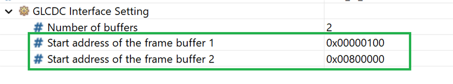
0x00000100, // Begin of On-Chip RAM
0x00800000 // Begin of Expansion RAM
};
//
// Define the available number of bytes available for the GUI
//
#define GUI_NUMBYTES (1024 * 49)
Capacitive touch: #define USE_MULTITOUCH 0 #define SLAVE_ADDRESS 0x38 #define MAX_NUM_TOUCHPOINTS 10 #define MAX_NUM_IDS 10 #define NUM_CALIB_POINTS 5 #define XSIZE 480 #define YSIZE 272 // // Reset touch ic // R_GPIO_PinDirectionSet(GPIO_PORT_0_PIN_7, GPIO_DIRECTION_OUTPUT); R_GPIO_PinWrite(GPIO_PORT_0_PIN_7, GPIO_LEVEL_LOW); R_BSP_SoftwareDelay(10, BSP_DELAY_MILLISECS); R_GPIO_PinWrite(GPIO_PORT_0_PIN_7, GPIO_LEVEL_HIGH); R_BSP_SoftwareDelay(300, BSP_DELAY_MILLISECS); // // Sets IIC Information (Ch6) // _Info.ch_no = 6; Even though the software stack has evolved since the road test times, it looks like most of the configuration settings are similar. This is useful, because the settings come from a proven working example. |
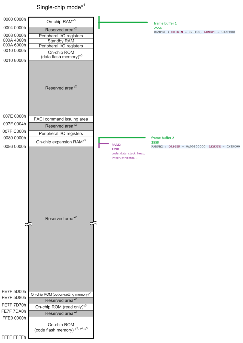
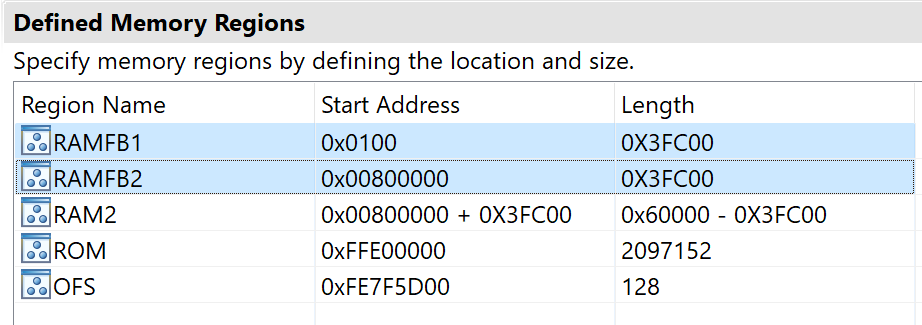
Proposed loader settings:
MEMORY
{
	RAMFB1 : ORIGIN = 0x0100, LENGTH = 0X3FC00
	RAMFB2 : ORIGIN = 0x00800000, LENGTH = 0X3FC00
	RAM2 : ORIGIN = 0x00800000 + 0X3FC00, LENGTH = 0x60000 - 0X3FC00
	ROM : ORIGIN = 0xFFE00000, LENGTH = 2097152
	OFS : ORIGIN = 0xFE7F5D00, LENGTH = 128
}
Software Configuration
This section is not correct yet. I will update this post while experimenting with the kit.
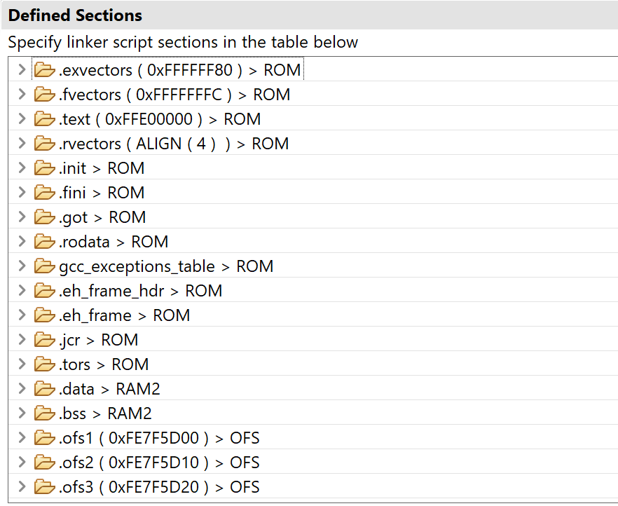
In the previous section, I reserved 2 memory sections for the 255K frame buffers:
buffer 1: 0x00000100
buffer 2: 0x00800000
The linker script is defined in a way, that all data , code, buffers, heaps, ... are now placed in the extended memory area, after buffer 2. And both buffer areas are reserved in the linker script. No section is placed in the 2 areas.
Full loader script:
MEMORY
{
	RAMFB1 : ORIGIN = 0x0100, LENGTH = 0X3FC00
	RAMFB2 : ORIGIN = 0x00800000, LENGTH = 0X3FC00
	RAM2 : ORIGIN = 0x00800000 + 0X3FC00, LENGTH = 0x60000 - 0X3FC00
	ROM : ORIGIN = 0xFFE00000, LENGTH = 2097152
	OFS : ORIGIN = 0xFE7F5D00, LENGTH = 128
}
SECTIONS
{
	.exvectors 0xFFFFFF80: AT(0xFFFFFF80)
	{
		"_exvectors_start" = .;
		KEEP(*(.exvectors))
	"_exvectors_end" = .;
	} >ROM
	.fvectors 0xFFFFFFFC: AT(0xFFFFFFFC)
	{
		KEEP(*(.fvectors))
	} > ROM
	.text 0xFFE00000: AT(0xFFE00000)
	{
		*(.text)
		*(.text.*)
		*(P)
		etext = .;
	} > ROM
	.rvectors ALIGN(4):
	{
		_rvectors_start = .;
		INCLUDE ../src/smc_gen/r_bsp/mcu/all/linker_script_rvectors.inc
		_rvectors_end = .;
	} > ROM
	.init :
	{
		KEEP(*(.init))
		__preinit_array_start = .;
		KEEP(*(.preinit_array))
		__preinit_array_end = .;
		__init_array_start = (. + 3) & ~ 3;
		KEEP(*(.init_array))
		KEEP(*(SORT(.init_array.*)))
		__init_array_end = .;
		__fini_array_start = .;
		KEEP(*(.fini_array))
		KEEP(*(SORT(.fini_array.*)))
		__fini_array_end = .;
	} > ROM
	.fini :
	{
		KEEP(*(.fini))
	} > ROM
	.got :
	{
		*(.got)
		*(.got.plt)
	} > ROM
	.rodata :
	{
		*(.rodata)
		*(.rodata.*)
		*(C_1)
		*(C_2)
		*(C)
		_erodata = .;
	} > ROM
	gcc_exceptions_table :
	{
	    KEEP (*(.gcc_except_table))
	    *(.gcc_except_table.*)
	} > ROM
	.eh_frame_hdr :
	{
		*(.eh_frame_hdr)
	} > ROM
	.eh_frame :
	{
		*(.eh_frame)
	} > ROM
	.jcr :
	{
		*(.jcr)
	} > ROM
	.tors :
	{
		__CTOR_LIST__ = .;
		. = ALIGN(2);
		___ctors = .;
		*(.ctors)
		___ctors_end = .;
		__CTOR_END__ = .;
		__DTOR_LIST__ = .;
		___dtors = .;
		*(.dtors)
		___dtors_end = .;
		__DTOR_END__ = .;
		. = ALIGN(2);
		_mdata = .;
	} > ROM
	.data : AT(_mdata)
	{
		_data = .;
		*(.data)
		*(.data.*)
		*(D)
		*(D_1)
		*(D_2)
		_edata = .;
	} > RAM2
	.bss :
	{
		_bss = .;
		*(.bss)
		*(.bss.**)
		*(COMMON)
		*(B)
		*(B_1)
		*(B_2)
		_ebss = .;
		. = ALIGN(128);
		_end = .;
	} > RAM2 AT>RAM2
	.ofs1 0xFE7F5D00: AT(0xFE7F5D00)
	{
		KEEP(*(.ofs1))
	} > OFS
	.ofs2 0xFE7F5D10: AT(0xFE7F5D10)
	{
		KEEP(*(.ofs2))
	} > OFS
	.ofs3 0xFE7F5D20: AT(0xFE7F5D20)
	{
		KEEP(*(.ofs3))
	} > OFS
	.ofs4 0xFE7F5D40: AT(0xFE7F5D40)
	{
		KEEP(*(.ofs4))
	} > OFS
	.ofs5 0xFE7F5D48: AT(0xFE7F5D48)
	{
		KEEP(*(.ofs5))
	} > OFS
	.ofs6 0xFE7F5D50: AT(0xFE7F5D50)
	{
		KEEP(*(.ofs6))
	} > OFS
	.ofs7 0xFE7F5D64: AT(0xFE7F5D64)
	{
		KEEP(*(.ofs7))
	} > OFS
	.ofs8 0xFE7F5D70: AT(0xFE7F5D70)
	{
		KEEP(*(.ofs8))
	} > OFS
.r_bsp_NULL :
	{
		. += 0x100;
		"_r_bsp_NULL_end" = .;
	} >RAM2 AT>RAM2
.r_bsp_istack ALIGN(0x4) (NOLOAD) :
	{
		KEEP(*(.r_bsp_istack))
	} >RAM2 AT>RAM2
.istack :
	{
		"_istack" = .;
	} >RAM2
.r_bsp_ustack ALIGN(0x4) (NOLOAD) :
	{
		KEEP(*(.r_bsp_ustack))
	} >RAM2 AT>RAM2
.ustack :
	{
		"_ustack" = .;
	} >RAM2
}
Let's now adapt the default wizard and config settings, with this info. In the screen captures below, I focused on the configuration that's different than the proposed wizard values, or the QE-How-To instructions.
QE for Display wizard:
emWin FIT module:
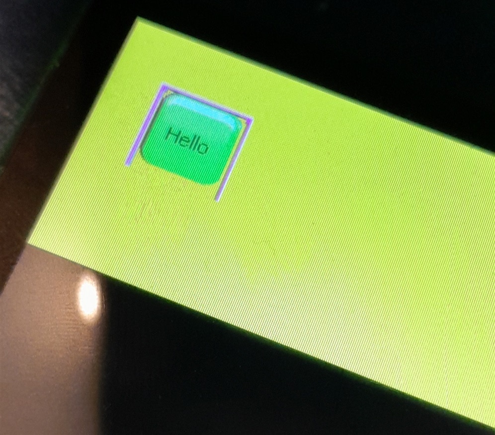
Result:
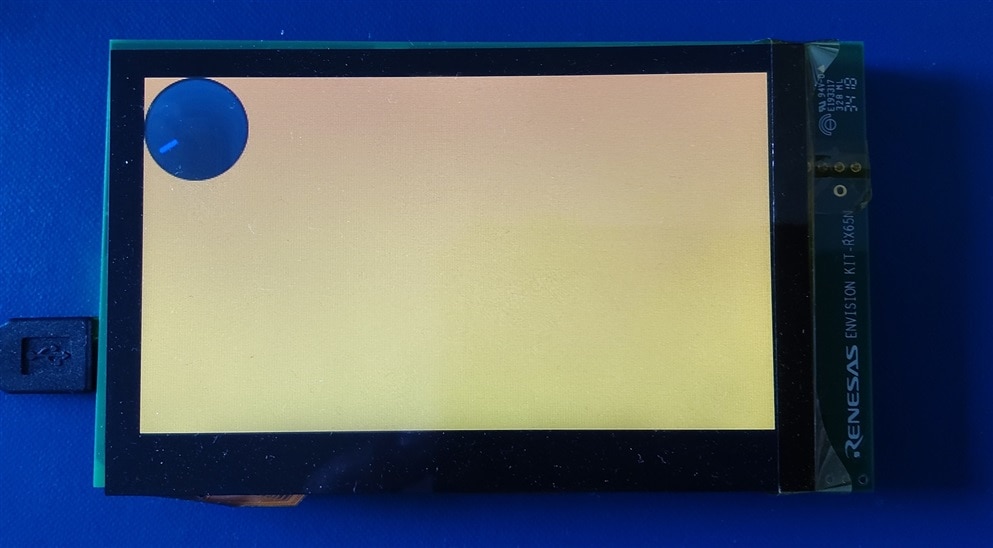
| * my road test screen was physically damaged on arrival and didn't show all lines. It held up for a while, but kept losing lines. I dis- and re-assembled it. That reverted the display to more-than-half-working. But I was unable to get the full screen. Now that I have Andrew J 's screen , I can proceed with my endeavours. I also have a bigger LCD screen (present from shabaz ). That works perfectly, but doesn't have a capacitive touch layer. I purchased a touch front end for that. But it's not a drop-in unit. I'll need to learn how to get that working in this environment. Food for a different blog chain. |
I did not attach the project due to emWin licensing restrictions:

The AppWizard generates a set of source codes, libs and executables in the project structure. Maybe, if I have time, I will create a project without these objects, and an explanation on how to generate the dependencies that I can't include.
Top Comments