I have this battery powered vacuum cleaner that I quite like, but it decided to stop working.
It uses 3x 18650 cells for power, and has two brushed motors, one for sucking air, the second for a rotating brush in the bottom.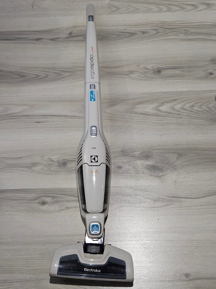
It can also be converted to a handheld vacuum: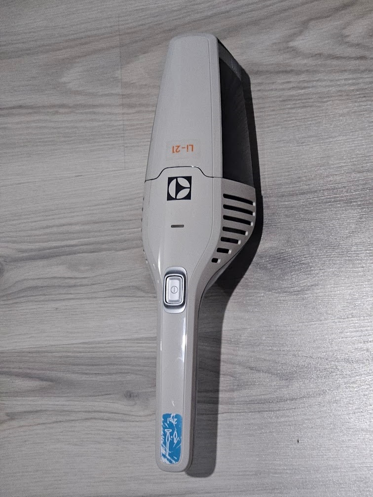
The thing is completely dead, it doesn't turn on, doesn't light up, doesn't charge, nothing.
Took it apart, this is the PCB inside:
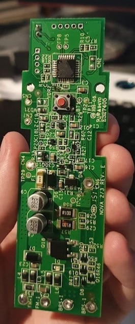
After some probing, it seems like the microcontroller is dead, so this entire board is trash.
I couldn't find a replacement one, so time to make something.
Custom PCB attempt 1
The functionality seems relatively simple:
- Charge/manage a 3S Li-Ion battery pack
- Turn the motors on and off
The sane way of doing this would probably be an off the shelf BMS with a charger module, and a relay + flip-flop to turn the motors on and off. That seems way too easy though, so doing it the hard way it is.
Here's the initial idea:
- BQ7791501 for battery balancing and protection. It's a neat little IC, supports 3-5S batteries, but multiple can be chained for larger packs. Does balancing and protection automagically without the need for a host microcontroller.
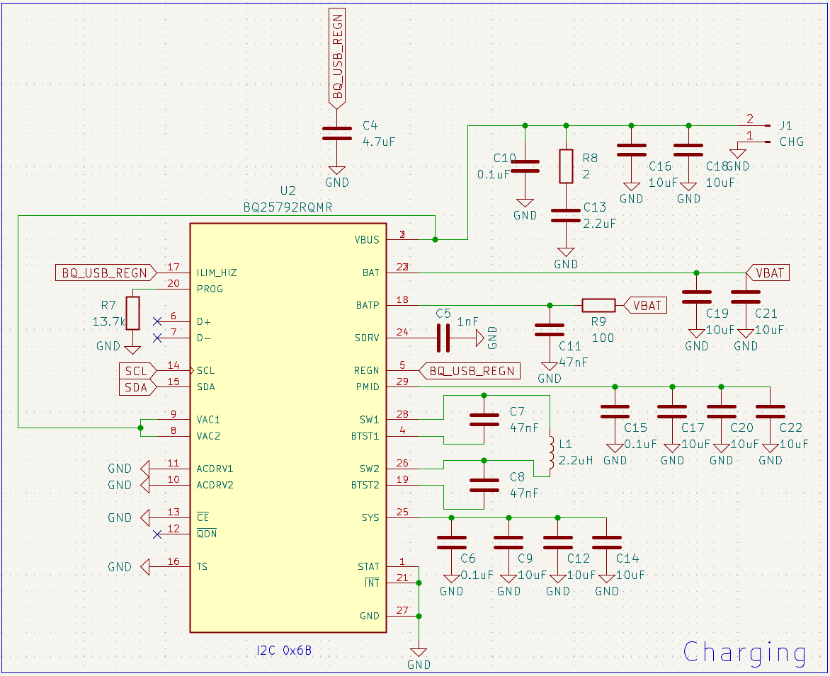
- BQ25798 for charging. I've had my eyes on this IC for a different project, so decided to test it out with this board. It takes 5-24V input, charges a 1-4S battery at 5A max, supports MPPT, has an ADC and can measure pretty much everything, all charging parameters and stages are configurable over I2C. Saying that it's overkill for this application is an understatement, but maybe I'll really need MPPT solar charging for my vacuum cleaner one day.
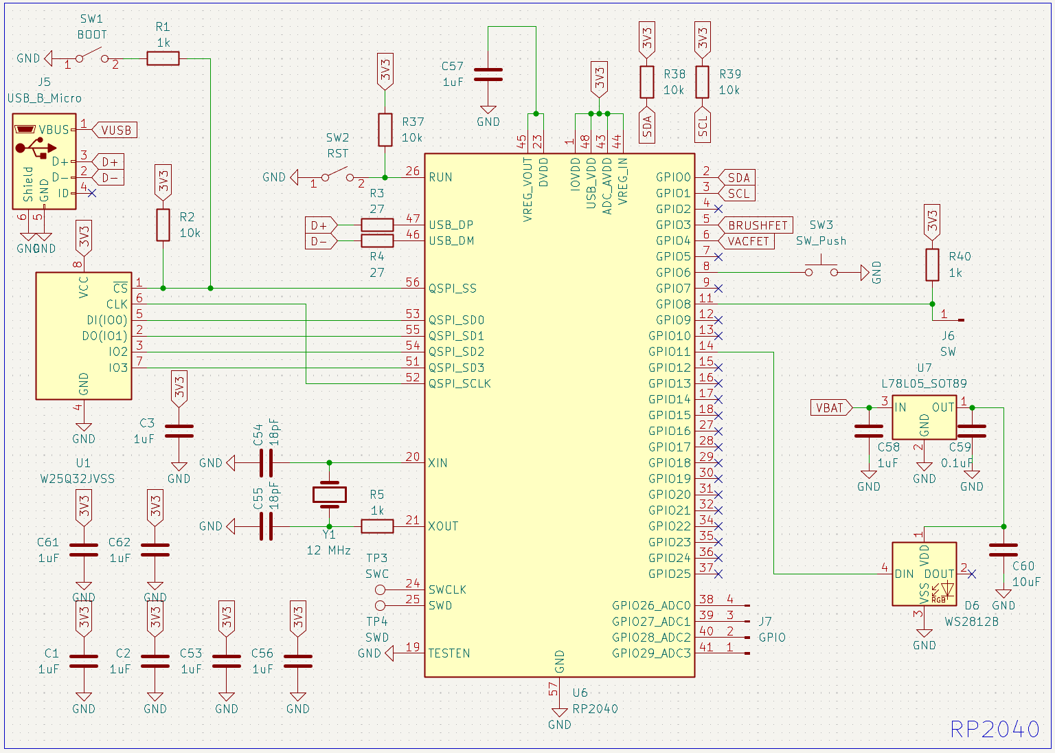
- RP2040 to control everything. Had a bunch of them, so why not. Pretty much any MCU would be sufficient for this project.
- Two MOSFETs to control the motors.
Some additional fancy features:
- WS2812B RGB LED instead of the single color one on the original board. There was no way to tell how charged up the battery was, which was quite annoying, so I wanted to use the RGB LED to indicate state-of-charge with colors.
- I didn't want to suffer trying to figure out battery state-of-charge manually, so I decided to use a BQ34Z100.
There are 4 contacts on the back of the unit: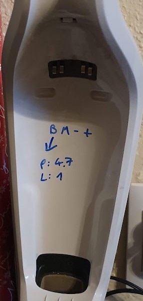
There's a common ground, charger input voltage, positive terminal of the brush motor in the bottom, and a pin coming from the two buttons at the top. Pressing the top button connects a 4.7k resistor between ground and this pin, while the bottom button uses 1k.
This is quite simple to use, I'll just need to make a voltage divider where one half is this 4.7k/1k resistor, and read the output voltage with the RP2040's ADC.
I also needed a 3.3V regulator to power things.
Here's the new PCB, next to the original one:
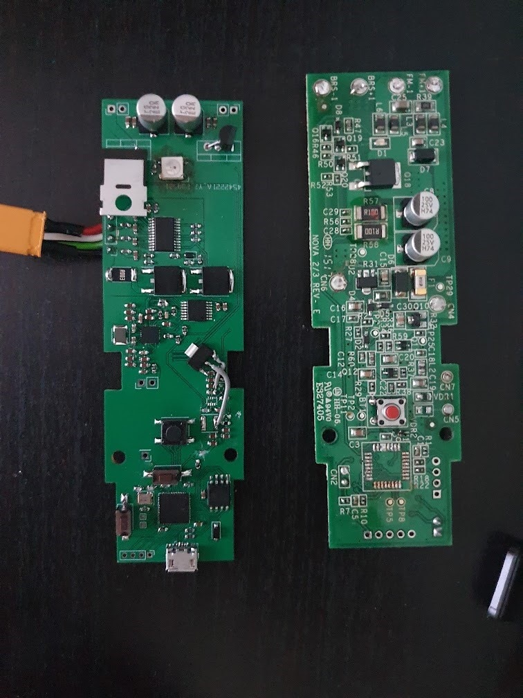
I somehow messed up the 3.3V regulator part, so bodged on a linear regulator instead.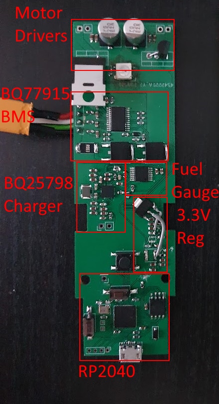
Fuel gauge issues
Turns out, the BQ34Z100 was a horrible idea. It looked like exactly what I need, but after writing a bunch of code for it, I realized there were no registers for configuring cell parameters. The only way to do that, is to buy TI's very expensive proprietary programming dongle thing and use their software.
Since I messed up the 3.3V regulator, and the motor driver part was kinda horrible and underpowered as well, I decided to rework the board a bit, and order a new version.
Custom PCB attempt 2
- I switched out the regulator for an IC I've used before, a TPS566231.
- Found a promising fuel gauge, the MAX17261
- Also added an INA226 to monitor pack voltage and current, in case the new fuel gauge doesn't work out either, so I can try to calculate battery SoC in software on the RP2040 as a makeshift fuel gauge.
- Made a proper motor driver section. Instead of driving the FET gates at 3.3V, I added simple gate drivers with an N-channel/P-channel MOSFET pair, to be able to use the full battery voltage to drive the main FET gate. This also let me use way smaller and cheaper FETs for actually driving the motors.
This version finally seemed to work, other than a very slight, major issue with the fuel gauge/INA226. I wanted to share one shunt resistor for the BMS, fuel gauge, and INA226, which turned out to be a bad idea.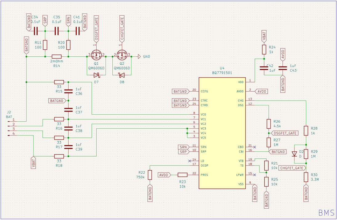
The BMS uses the battery pack's negative terminal as its ground, and the rest of the board is connected to pack ground through back-to-back N-MOSFETs, which the BMS controls.
Normally, this isn't a problem. The MOSFETs have very low on resistance, so pack ground and board ground is essentially the same. The issue is when the motors start running, and 15A goes through the two MOSFETs.
Each FET has an RDSon of 18mOhm, which means there will be a 0.54V drop through them when drawing 15A. Since the shunt resistor is before the FETs, it means there will be a common mode voltage of -0.54V at the two shunt input pins of the fuel gauge. The MAX17261 datasheet specifies an absolute maximum rating of -0.3V to Vbatt+0.3V.
The solution is to add a second shunt resistor AFTER the N-FETs. Fortunately, I was able to bodge in a new shunt and rewire the fuel gauge and INA226.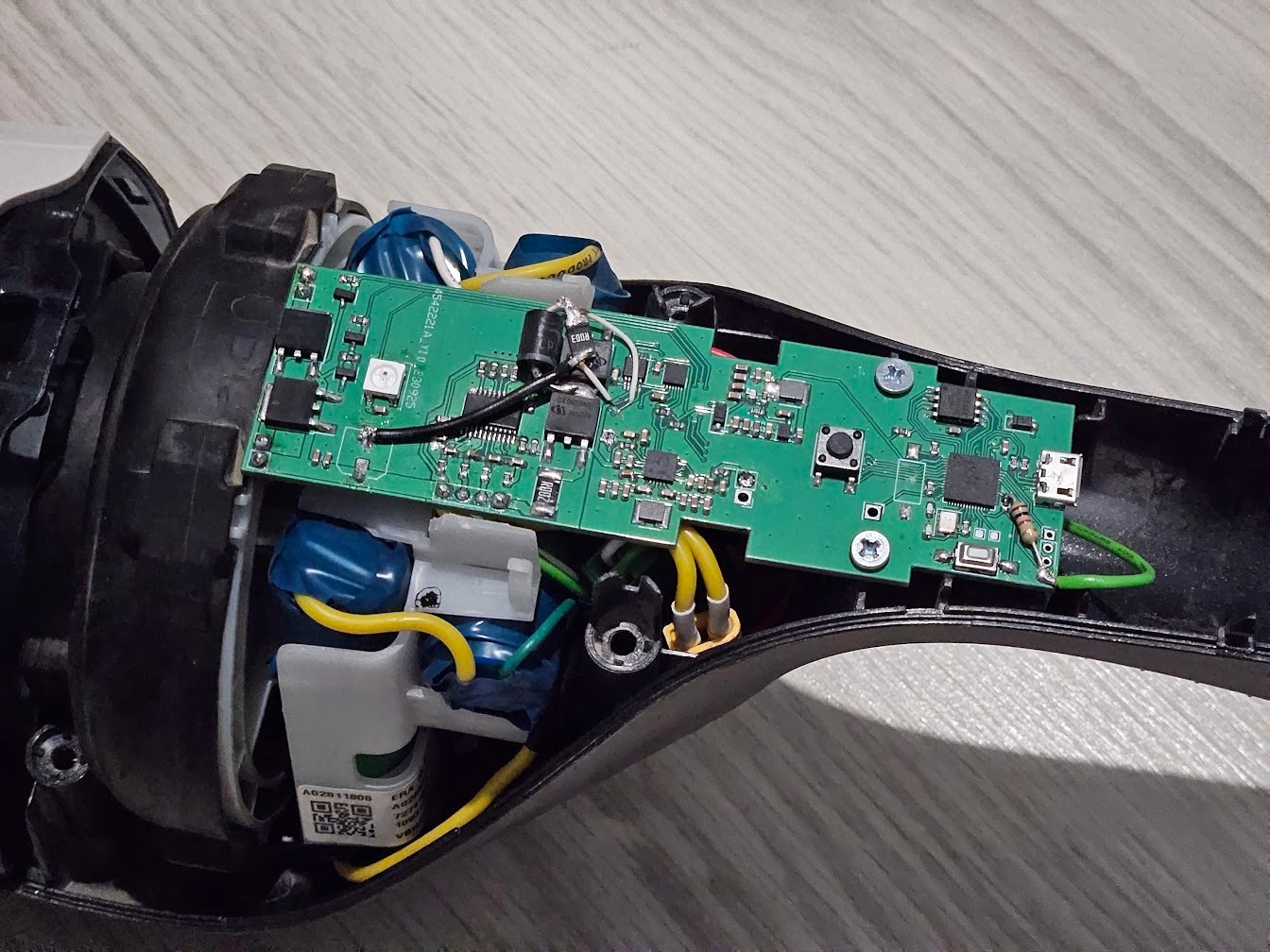
I completely forgot about the two buttons, but I did add pads for some unused GPIOs on the RP2040, and some of them happened to be ADC pins, so I only had to bodge a resistor on.
Here are the schematics for various parts of the PCB (I did not correct the shunt resistor issue here, so if you copy this, make sure to fix it as described above):



Software
I ended up writing a relatively feature-complete library for the BQ25798, I'll try and clean it up some time later and release it publicly for others to use.
The MAX17261 ended up working perfectly, although the datasheets were a bit disorganized.
The code isn't too complicated, all it has to do is read battery SoC from the MAX17261 and set the RGB LED to some color based on the value when the vacuum cleaner is on or charging. The power buttons simply toggle the two FETs on or off, the second button on the "base" switches to a "low power" mode by using 50% duty cycle PWM to drive the FETs instead of always on. Some parts of the code ended up a bit janky, so I'm not posting it (yet), if I have time to clean that up as well, I'll edit this blog to include it.
Conclusion
Overall, I'm very happy with how everything turned out, even though it would've probably been cheaper to buy another used vacuum cleaner. At least if anything fails now, I can fix it easier.
The MAX17261 "just works", doesn't have any over-complicated features, just set a few basic parameters and it gives you SoC.
The BQ25798 is amazing as well, the datasheet is great, every detail is explained superbly, all the registers are documented with examples, the IC is very configurable and easy to use, and does its job without any problems. All the charging states are configurable and can even be disabled completely, thanks to this I was able to reconfigure one of them to charge lead-acid batteries as well(this is officially not supported, only Li/NiMH). The built-in ADC can monitor input voltage/current, battery voltage, charging current, IC temperature, battery thermistor over I2C.
The only complaints I have about it are the package/footprint, and their MPPT implementation. There is no thermal pad at the bottom, so getting heat away from the IC is very difficult. It uses a weird TI package I've never seen before: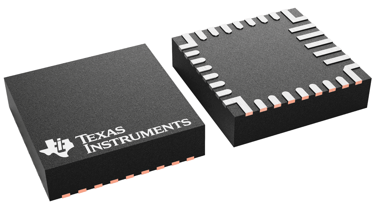
The lack of surface area for conducting heat away means it's basically impossible to cool the chip when it's doing over 3.5A output current. In a different project I'm working on, I tried to optimize the PCB layout for cooling, added a heatsink on top of the IC and on the underside of the PCB as well, with active cooling from both sides too, and the maximum I was able to achieve is slightly under 4A continuous. The IC claims to be able to do 5A max, so this is a bit disappointing.
Another slight annoyance is the MPPT implementation, instead of doing "true" MPPT, it measures open-circuit voltage of the solar panel every once in a while, and uses a percentage of that as the target voltage(this percentage, and the measurement interval are configurable over I2C). This works okay-ish, it's definitely way better than no MPPT at all, but "true" MPPT would be so much nicer(like the BQ25756 has).


Top Comments
-

scottiebabe
-
Cancel
-
Vote Up
+1
Vote Down
-
-
Sign in to reply
-
More
-
Cancel
Comment-

scottiebabe
-
Cancel
-
Vote Up
+1
Vote Down
-
-
Sign in to reply
-
More
-
Cancel
Children