Table of Contents
Introduction
XMOS parts are interesting. They are at the heart of many smart home products, AI assistants, and Hi-Fi music solutions. The key to understanding the reason why, is to take a peek at how XMOS processors function, and I’ll attempt a dive into that in a future blog post!
This blog on the new(ish) XMOS xcore.ai parts merely introduces an evaluation board, called XK-EVK-XU316, and describes the steps to set up the PC to be ready to work with XMOS devices, and walks through a simple example that demonstrates how GPIO ports can be used to output signals at precise timestamps.
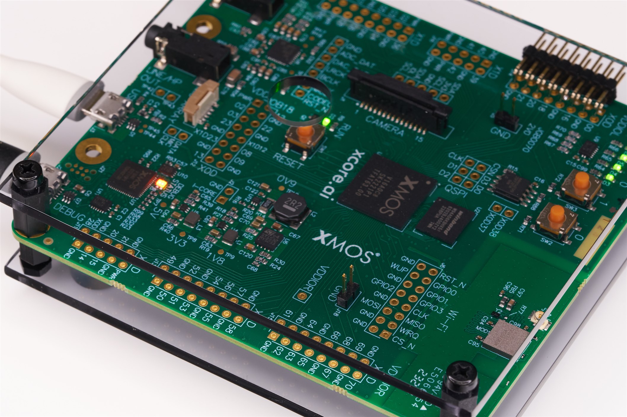
I’ll leave the xcore.ai internals discussion for another blog post, but for now, if you’re new to XMOS parts, at a birds-eye view, they can be assumed to be a multi-core, multi-threaded processor with capabilities normally seen in software-based operating systems, but actually implemented in silicon. If code can be architected to make use of more than one hardware thread (known as ‘xcore logical cores’ in XMOS terminology; for more information on this, check out the xcore.ai white paper [PDF]), then there are huge performance gains versus a normal microcontroller because the throughput (again, at a birds-eye view) simply multiplies; that’s not the case with traditional (software) threads based on context-switching.
There are benefits and disadvantages to all approaches, but one big advantage of XMOS devices compared to FPGA-only solutions is that there’s no need to be familiar with digital design. A C/C++ programmer can code for XMOS parts from day one. And the software and debug tools are nice; they are what software developers will hopefully expect. The development environment runs on Windows, Mac and Linux, accessed from the command prompt or scripts, and ties in well with VS Code.
If you wish to follow along, you don’t necessarily need the evaluation board, but it helps. The eval board isn’t an impulse purchase price, but certainly not an excessive cost, either. It is very fairly priced, given the amount of functionality on it; check out the annotated board photo further below.
But first, the photo snippet here shows the heart of it, the main processor system, containing the XMOS device, the SPI Flash, and power supplies. The SDRAM chip visible in the photo (north of the XMOS part) would not be needed for all applications but would be useful for storing (say) large amounts of data captured for processing or transmission. To put it in perspective, it could easily support several hundred times more RAM storage than a conventional microcontroller might have built in. It’s very unusual to have such a powerful memory interface for a microcontroller, and it’s only available if you’re using the BGA-packaged XMOS part as this board is using, instead of QFN or TQFP variants (and all packages have a decent amount of RAM, 1 Mbyte, internally, and internal throughput is very high if code is designed to allow many cores to access it; each core can access 256 bits, i.e. 32 bytes! per clock cycle).
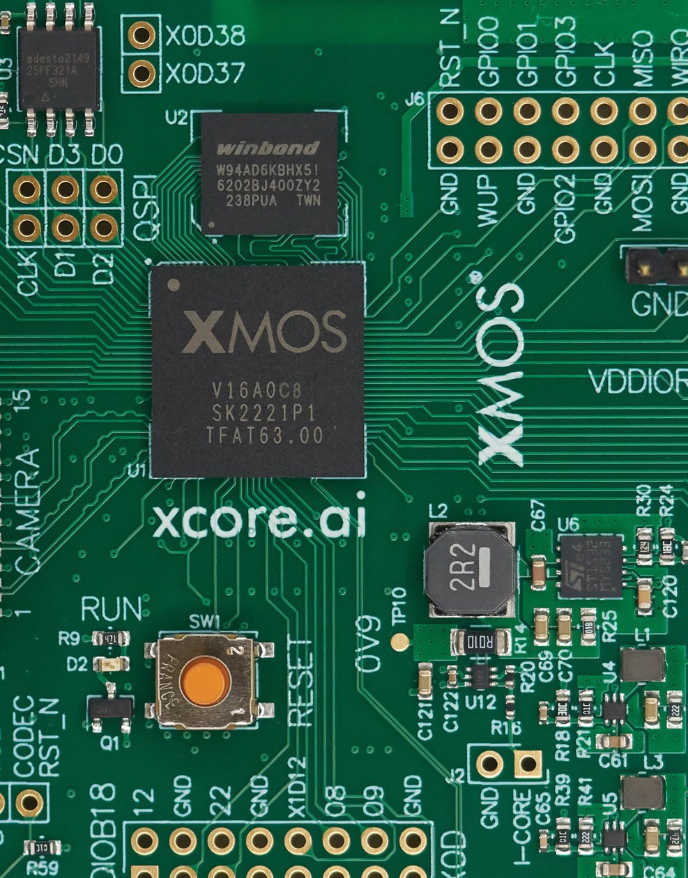
A 24 MHz crystal and all decoupling capacitors are on the underside. The core power supply is 0.9V, and the evaluation board also contains 3.3V and 1.8V supplies for input/output signals.
If you wanted to make a minimal XMOS system for (say) a 3.3V system, then the main things you’d need are the XMOS microcontroller, a 0.9V core, and a 3.3V I/O supply, and an SPI Flash chip. You’d also ideally purchase a (cheap) XTAG-4 debugger tool, although that can be worked around, having it will make life a lot easier for the developer.
Building a minimal XMOS system will be the subject of another blog, so if you have ideas, it would be great to hear them.
Exploring the XK-EVK-XU316 Evaluation Board
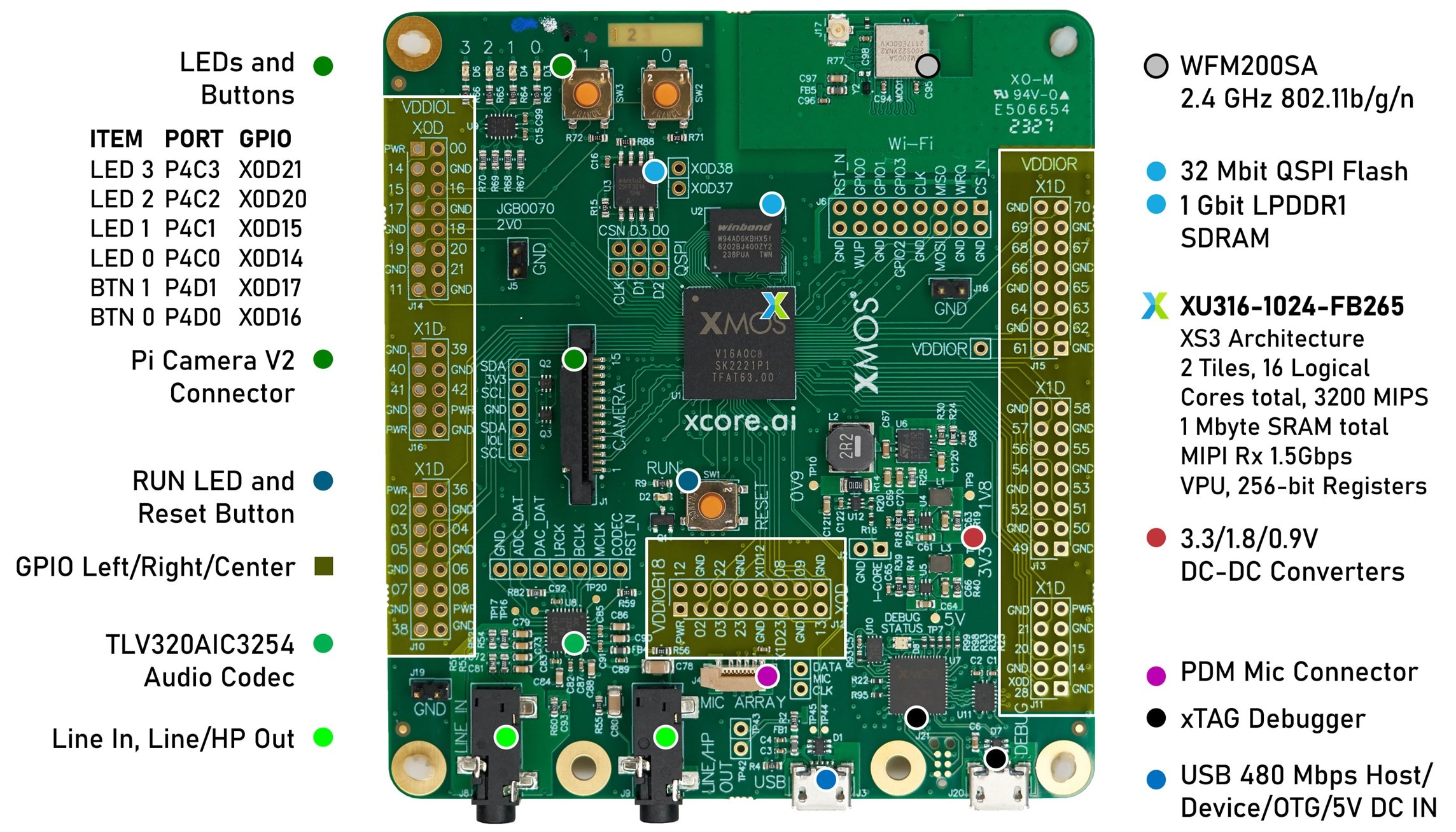
The board is well thought out, and I liked it. It breaks out loads of GPIO to the left and right side (these are at 3.3V logic levels but can be switched to 1.8V logic), and there is a central portion of GPIO, which is set to 1.8V only on the eval board.
You can also see that there is a built-in audio codec, connections for an optional microphone, and a Raspberry Pi camera.
There are some LEDs and buttons on the board, plus an 802.11 (wireless) module.
Power and computer interfacing is at the bottom of the board, using two micro USB connectors.
Getting Started with the Hardware
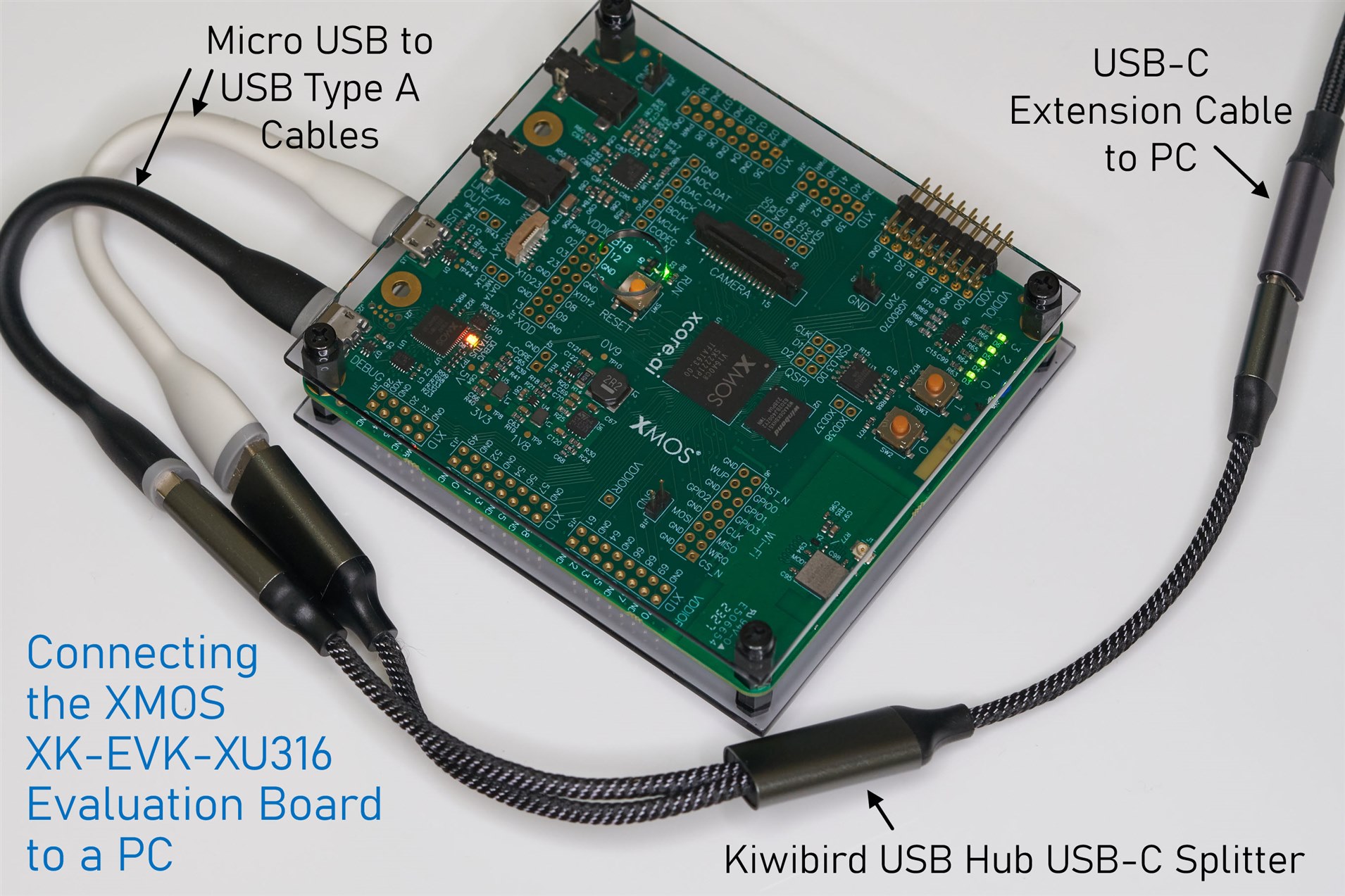
Minimally, you’d use two micro-USB cables to power up the board and access the on-board debugger via USB. To simplify connections to the PC, you could use a USB hub. I used a little splitter cable with built-in hub functionality. Don’t plug it into the PC just yet however; first the software needs to be installed, as discussed below.
You might also want to purchase pin headers to make accessing the GPIO easier. Also, some audio cables and headphones/earphones could be handy for trying out digital signal processing (DSP) applications. There is a different XMOS evaluation board, incidentally, for those more focused on audio applications for the devices.
Installing XTC Tools
XTC Tools are the fundamental pieces of software needed to compile, simulate, program, and debug for the XMOS devices. The XTC tools are used from the command line, but can be scripted or automated in various ways.
Download XTC Tools for Windows, Mac or Linux from https://www.xmos.com/software-tools/
I downloaded the latest, version 15.3.0 for me.
The instructions can be followed, and they specify that CMake, Git, and VS Code should be installed. My PC already had those.
Next, you’ll need to plug the XMOS Eval Board into your PC. Both USB connectors on the board need to be plugged into the PC (because one connector is used for the debug interface, and the other is used for power and USB access for user applications running on the microcontroller). As mentioned earlier, you could use a little USB hub, to reduce the connections to the PC.
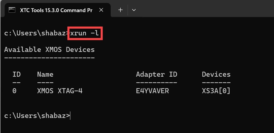
With the USB cables plugged in, the four LEDs in the corner of the board blink in a particular sequence by default. I could see in Windows Device Manager that an XMOS XTAG-4 device had appeared under Universal Serial Bus Devices. I launched the XTC Tools Windows Command Prompt and then typed:
xrun -l
Example Code
XTC Tools comes with some example code; it will be in a folder named C:\Program Files\XMOS\XTC\15.3.0\examples or similar. It’s best to copy any example from there into a different folder if you wish to experiment with them. For example, I created a folder called C:\development\xmos to house all my XMOS projects, and so I placed any project folders inside there.
Typically, if you’re using an example project and renaming it to something else, then the following steps will be needed:
- In the copied project folder (renamed to whatever you wish), remove any old build and binary folders (they may be called bin and build, for example)
- Go into the .vscode folder and confirm that any settings.json file there doesn’t contain any file paths. Then, open the tasks.json file there, and search for the text “.xe” to see the binary executable filename, and replace each occurrence with the new name you want for the project.
- Edit the CMakeLists.txt file and change the project name on the line containing the text project.
Working with VS Code
The steps described here will allow the developer to write code, build it, and then upload it onto the XMOS board to run it. If you’ve already gone through this section of the blog post, then this table can act as a quick summary for next time, and you can skip the rest of the section.
| Task | Procedure |
| Check if the board is connected | Launch the XTC Windows Command Prompt, navigate to your project folder, and type xrun -l and you should see an XMOS XTAG-4 detected |
| Launch VS Code | In the command prompt, from the project folder, type (including the period):code .The first time this is done for a project, you’ll be prompted to Select a Kit. Choose ‘Unspecified’ |
| Build the code | In VS Code, select the CMake icon (looks like a triangle with a wrench) and then in the Project Status pane, select the icon that appears when you hover over the text Build |
| Run the code | In VS Code, select the Explorer icon, and then under Task Runner, you can click on either Run, or Flash (depending on if you want the code to run temporarily on the board or stored in the on-board SPI Flash) |
Here’s the longer description.
Start up VS Code, and install a couple of extensions if you don’t already have them installed: CMake Tools by Microsoft and Task Runner by Sana Ajani. Next, click on View->Command Palette and in the box that appears, type settings and select Preferences: Open User Settings (JSON). Add the following entry in the settings file, and save it:
"files.associations": { "*.xc": "c" }
The reason for doing that, is because XMOS applications can be written in both normal C code, as well as a slightly modified version called XC (which I personally like, but I’ll stick to normal C for this blog post).
XMOS software projects typically make use of CMake, which relies on files called CMakeLists.txt. VS Code can be launched and automatically recognize that a folder contains a CMake project if you run VS code from inside the folder.
So, for instance, if a project resides in C:/development/xmos/example, then to launch it in VS Code, you’d start up the XTC Windows Command Prompt, and then change the directory to that example folder, and then type:
code .
Incidentally, if that command is not recognized, you’ll need to go into the Windows Environment Variables configuration and add the VS Code path to the PATH user or environment variable. In my case, the path was:
C:\Users\myusername\AppData\Local\Programs\Microsoft VS Code
Once launched, there’s a step that needs to be done, which concerns selecting CMake in the left-side icons, and then under Configure, click on [No Kit Selected] and then choose “unspecified”. Note that you may automatically be prompted at startup the first time, so you can simply select “unspecified” if prompted.
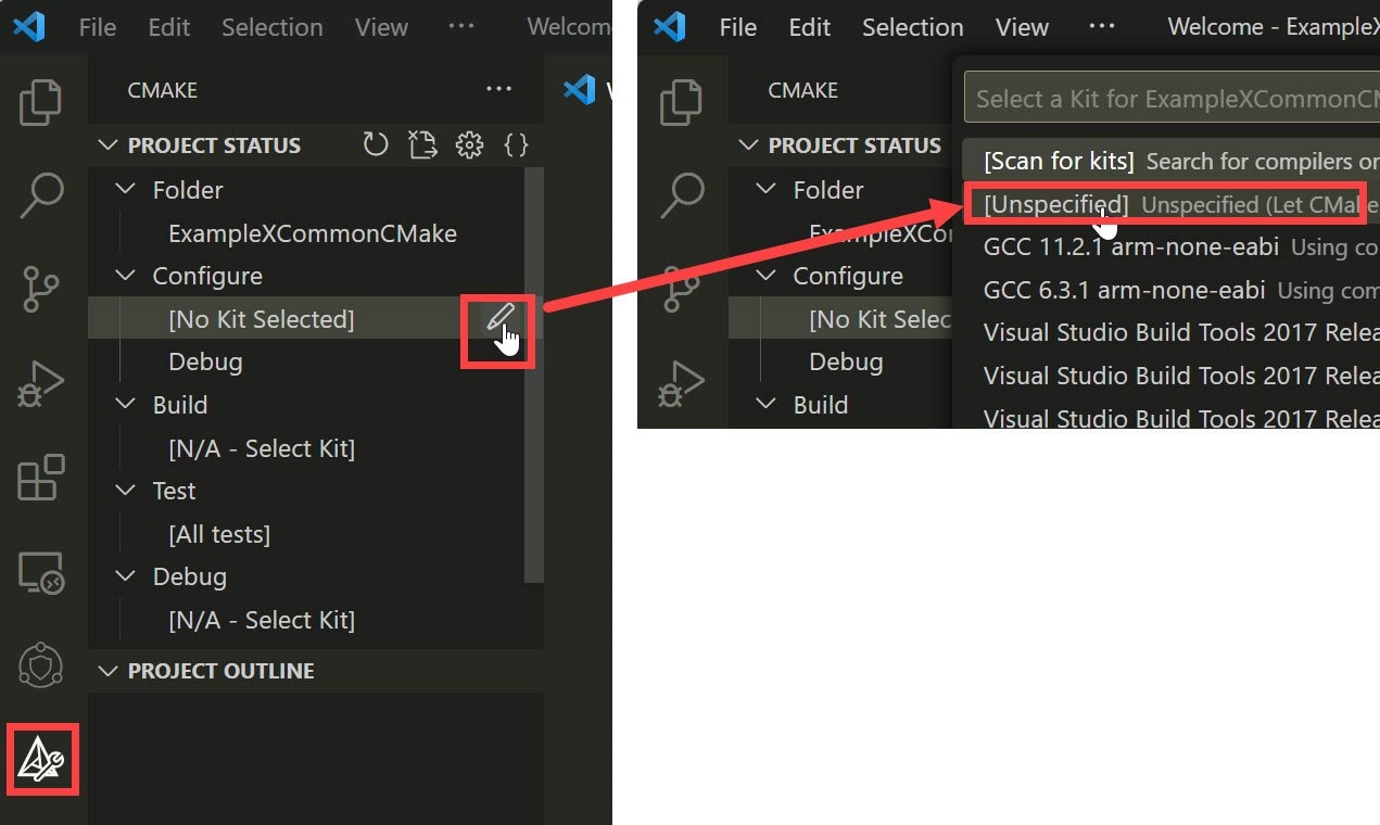
Once you do that, then you should see the following output. If you don’t see it, close and restart VS Code (using the same “code .” command as before), and give it a second or two, and the output should appear.
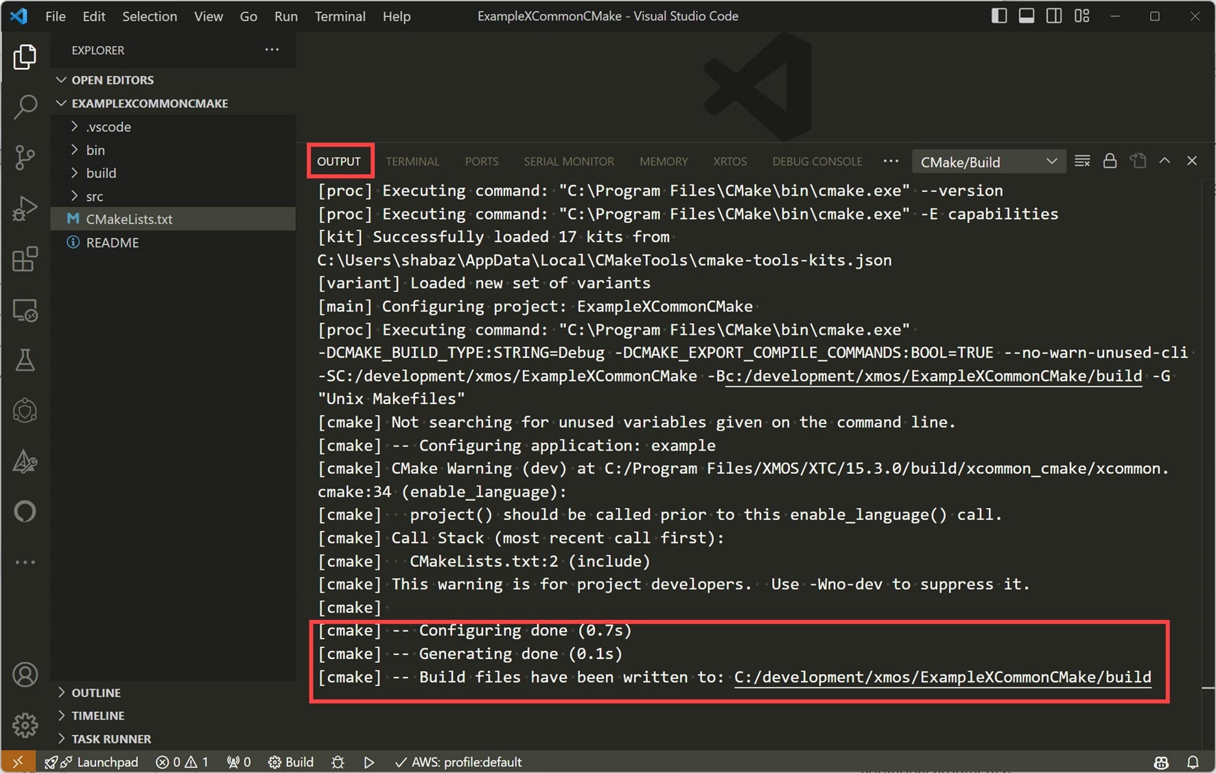
If there’s an error and you don’t see that, then that could be because either the CMakeLists.txt file is missing from your project folder where you launched VS Code from, or perhaps the VS Code user settings JSON file needs correcting (there is a cmake.cmakePath setting there, which needs to point to the full path and filename for cmake.exe, which should usually be:
"cmake.cmakePath": "C:\\Program Files\\CMake\\bin\\cmake.exe",
If all has gone well, then build and bin folders will have been created within the project folder.
Now the code can be built!
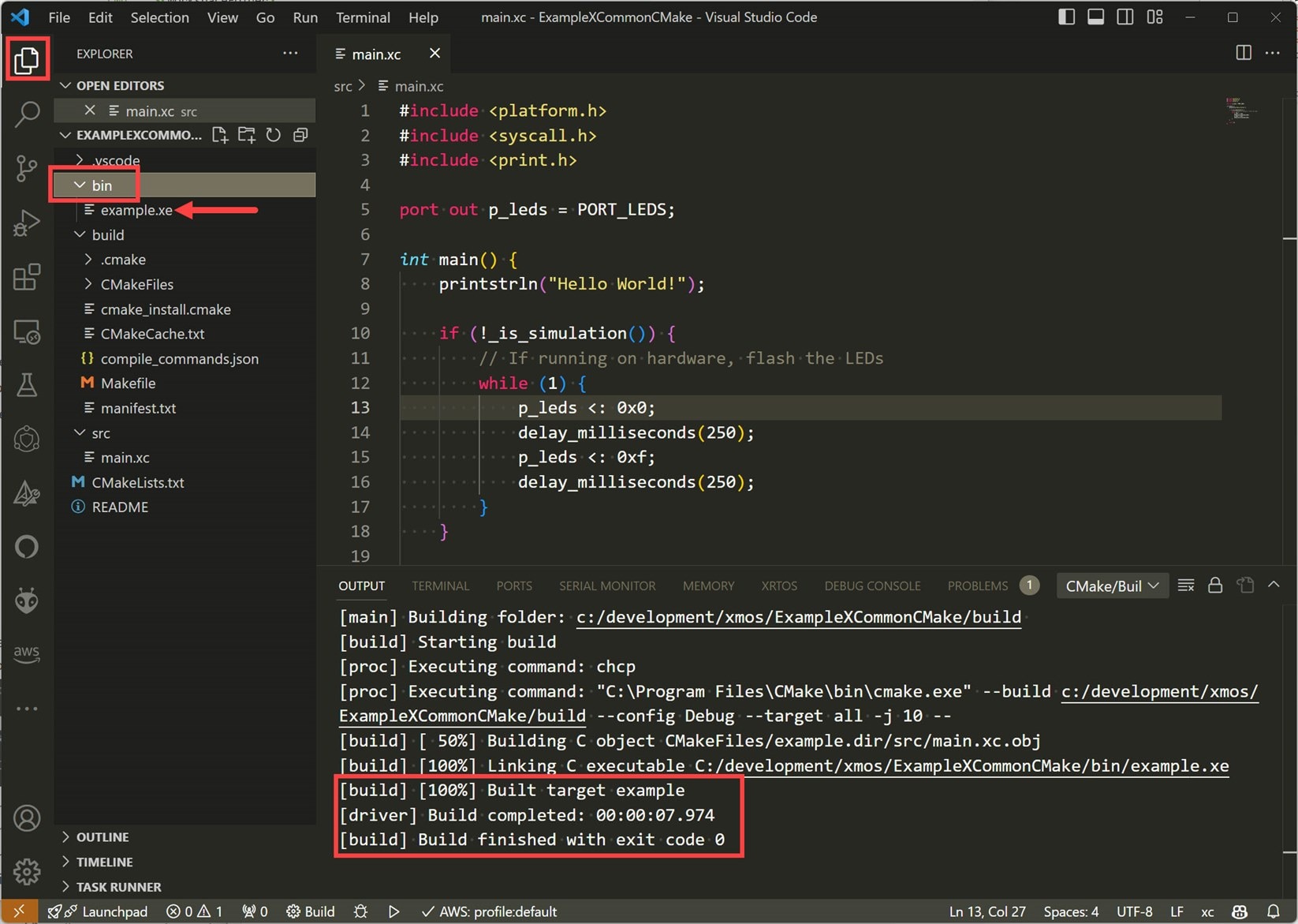
Click on the CMake icon in the left side panel, and then hover next to Build to see the little icon to click on.
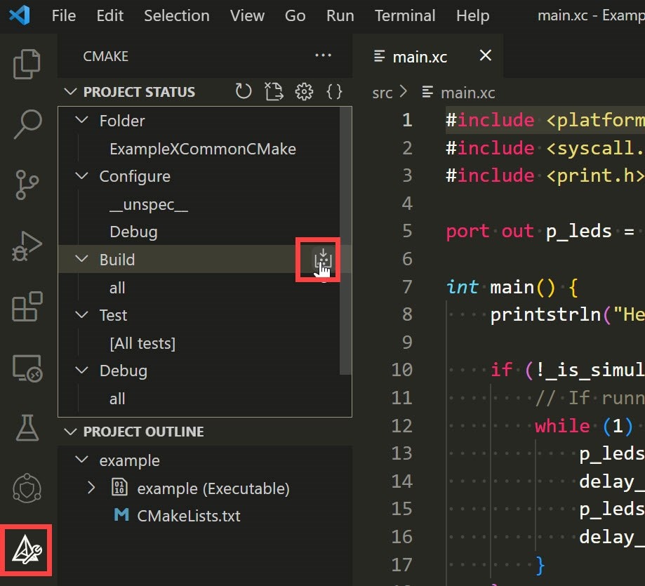
If all goes well, you should see the output shown below. The bin folder should now contain a .xe suffixed file! This file contains the built firmware, which will be uploaded to the XMOS board.
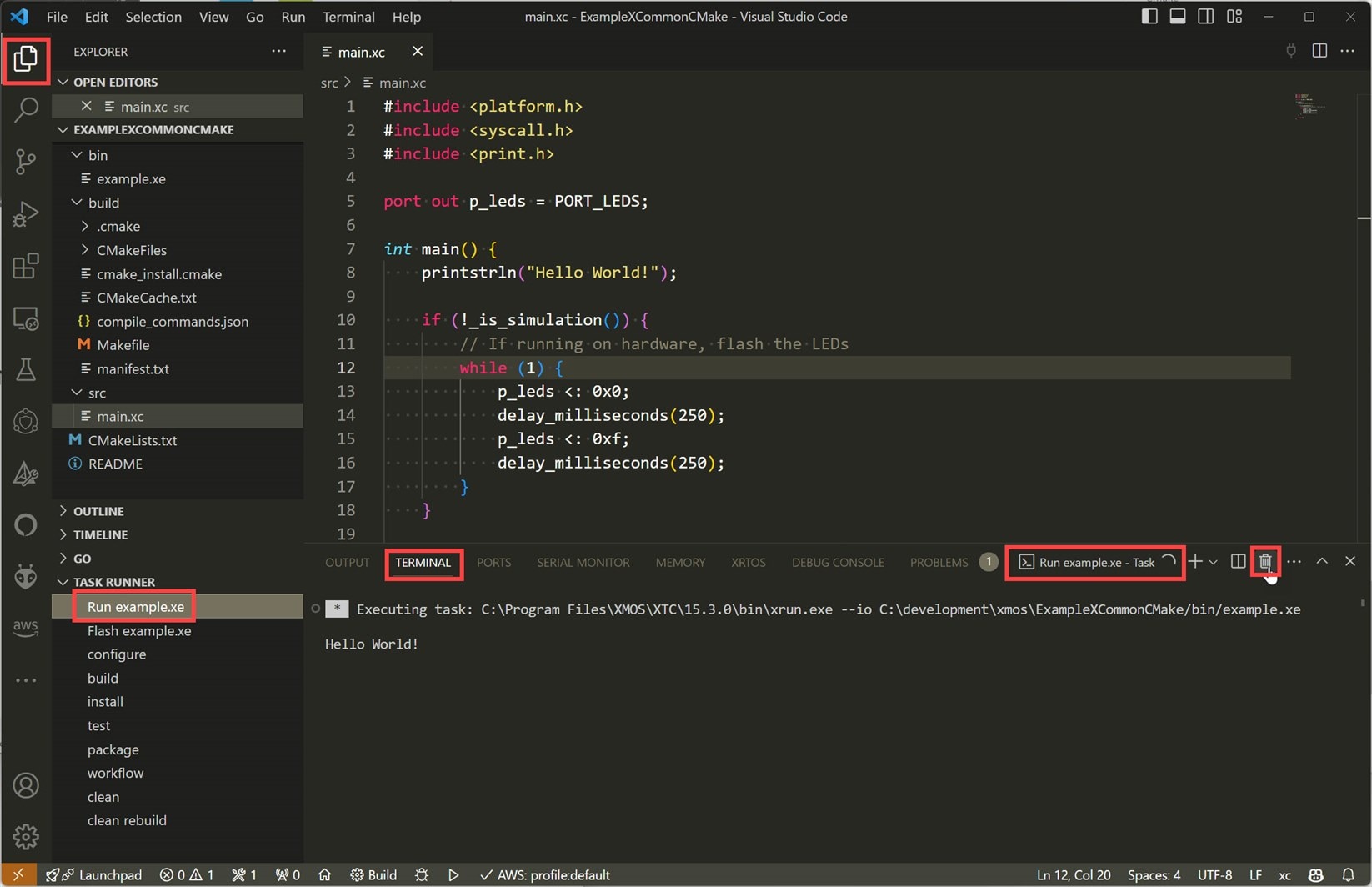
To run the code, click on the Explorer icon in the left pane, and then expand the Task Runner if it’s not already expanded. There are Run and Flash options there. During development, you could select Run, and the code will be temporarily uploaded to the board, and start running. Once you’re done, press the trashcan icon shown in the screenshot below, to kill the terminal view. To place the code into the QSPI Flash chip on the board so that it persists after reboots, select Flash from the Task Runner.
Command Line Operations
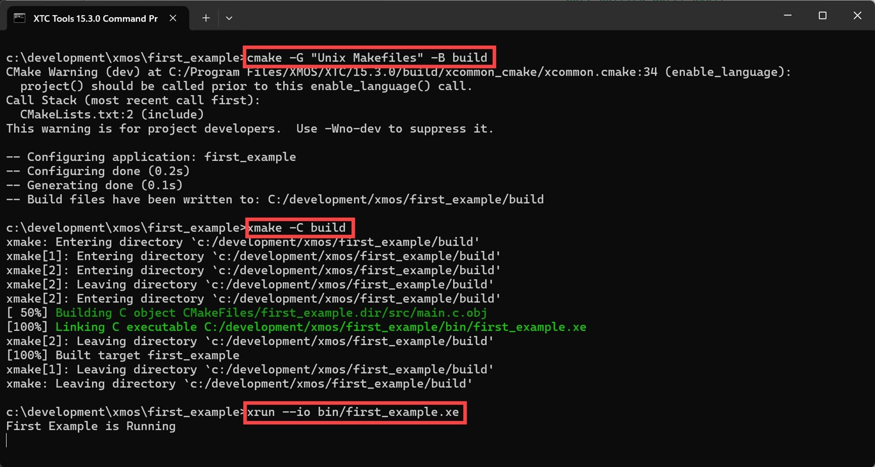
If you’re more of a command-line interface (CLI) guru, or if you wish to automate tasks, then the code can indeed be built and run from the command line instead. Typically, you’d type the following in the XTC Tools command prompt:
cmake -G "Unix Makefiles" -B buildxmake -C buildxrun --io bin/my_project_name.xe
Example Project: GPIO Output using Port Counters
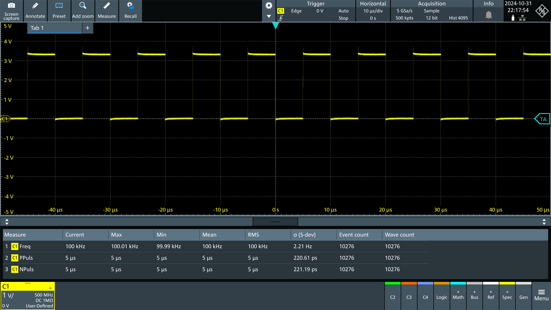
XMOS devices have quite sophisticated GPIO and clock capabilities, intended to allow interfacing to all manner of hardware, with internal or external clocking, with parallel or serial data along with ancillary signals that may be required. I’m only going to be using a fraction of functionality for this example. My aim was to toggle a GPIO pin in code, to create a 100 kHz square wave. With a normal microcontroller, you’d either need to handle this using a timer interrupt, or you’d have to configure a hardware timer peripheral to automatically generate the waveform, if the microcontroller supported this.
With XMOS devices, you can easily do it in the main program flow, by retrieving a clock count value indicating precisely when the previous port output occurred, and then set an incremented count condition against the next port output command! It means that the desired signal (a square wave in this example, but it doesn’t need to be!) will be output with precision, limited solely by the jitter from whatever clock is available. For high precision, you could feed an external clock. I used the internal clock (derived from an external crystal, but multiplied inside the XMOS chip) for the purposes of this example.
Although this example just generates a square wave, it is clear to see that you could drive (say) a Digital-to-Analog Converter (DAC) at precise clock count values, which is exactly what some commercial audio DAC products would make use of, with an XMOS part inside; it results in a high-quality audio output.
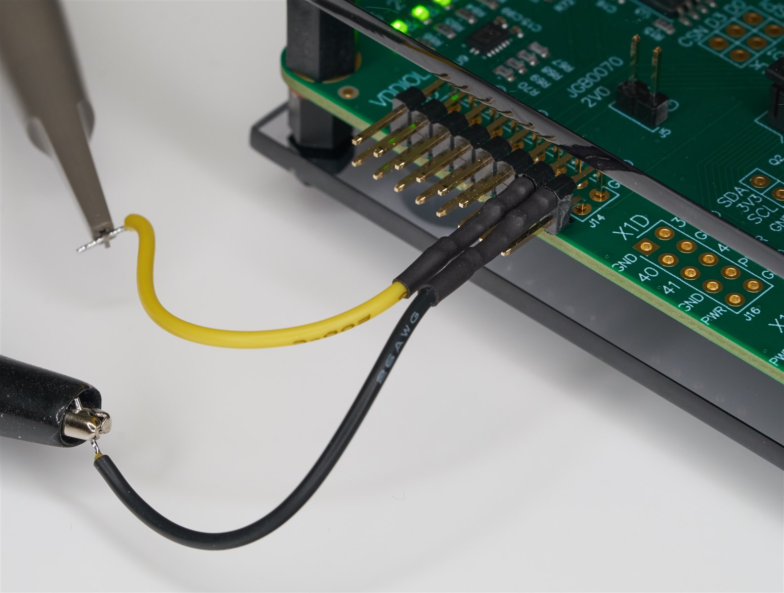
Anyway, back to the example, I wired up an oscilloscope to one of the GPIO pins, as shown in the photo here. There are four LEDs in a row on the evaluation board, and those connections are also present on the DIL header, and I connected up the oscilloscope to one of those connections.
Here’s an explanation of the main code (available on GitHub), line-by-line.
First, GPIO port and clock resources are defined.
According to the evaluation board schematic, four LEDs are wired to connections that can (if desired) act as a 4-bit port called port 4C (the 4 prefix signifies it is a 4-bit port). The variable called led_port is set to a port 4C identifier. The XMOS part datasheet can be consulted to see what physical pins that maps to.
There are about a dozen programmable clocks (known as clock blocks) inside the XMOS chip. A variable called clock_handle is assigned to one of them.
port_t led_port = XS1_PORT_4C;xclock_t clock_handle = XS1_CLKBLK_1;
Next, the GPIO port and the clock are enabled (this needs to be done before any other operation on these resources):
port_enable(led_port);clock_enable(clock_handle);
Simple so far! Next, I decided to set the clock module to obtain its clock source from a 100 MHz reference clock inside the chip. Since I was only interested in a 10 kHz square wave, I picked a value and chose to divide that clock by 100.
clock_set_source_clk_ref(clock_handle); // set the clock source to 100 MHz, i.e. 10 nsec periodclock_set_divide(clock_handle, 50); // divide the clock by 2*50 (100) to get 1 MHz, i.e. 1 usec period
Next, the clock is started, and the clock is assigned to be a counter for that 4C port.
clock_start(clock_handle);port_set_clock(led_port, clock_handle);
By doing that, one has the ability to query the counter whenever a port output is updated and also be able to set a count condition for the next port output!
The rest of the code consists of a forever loop where the following occurs:
A state variable is toggled:
led_state = !led_state;
Depending on the state value, the four LEDs are switched on or off using the port_out function:
if (led_state) { port_out(led_port, 0xf); } else { port_out(led_port, 0x0); }
Next comes the interesting part: the port hardware is queried to see when the port was updated. It returns the count value:
tstamp = port_get_trigger_time(led_port);
Now, the port hardware can be programmed to only allow the port_out to occur at a precise future count value:
port_set_trigger_time(led_port, tstamp + 5);
When the code loops, the port_out function will cause code execution to pause in this “hardware thread” that was discussed earlier until the counter value matches the programmed value.
Assuming you’ve installed XTC Tools, then to build and run the code, either follow the VS Code steps described earlier or follow the command line operations section above.
The end result is a stable, precise 100 kHz signal, as expected. As mentioned earlier, any jitter is purely an artifact of the clock circuitry used (including PLL). You could, if desired, reduce this further by attaching an additional clock oscillator to the circuit, and using that as the clock source to the port counter.
Summary
The xcore.ai Evaluation Kit shows promise; it contains a lot of on-board functionality, but the most interesting part is the xcore.ai chip, which contains multiple execution threads with dedicated hardware for each one (known as xcore logical cores).
It was straightforward to attach the Evaluation Kit to the PC, and install the XMOS development environment, which consists of XTC Tools (compiler, simulator, debugger and programmer) and VS Code.
A first example application was written, which demonstrates how to attach a clock to the counter mechanism that GPIO ports have, such that port output operations could occur at specific times to generate a precise 100 kHz signal within C code.
In a future blog, I’ll hopefully explore the XMOS xcore.ai architecture a little and try some more coding experiments to get up-to-speed with some of the capabilities. It will be good to design a simple XMOS dev-board too.
Thanks for reading!
