element14 Community
element14 Community
    Register Log In
  • Site
  • Search
  • Log In Register
  • About Us
  • Community Hub
    Community Hub
    • What's New on element14
    • Feedback and Support
    • Benefits of Membership
    • Personal Blogs
    • Members Area
    • Achievement Levels
  • Learn
    Learn
    • Ask an Expert
    • eBooks
    • element14 presents
    • Learning Center
    • Tech Spotlight
    • STEM Academy
    • Webinars, Training and Events
    • Learning Groups
  • Technologies
    Technologies
    • 3D Printing
    • FPGA
    • Industrial Automation
    • Internet of Things
    • Power & Energy
    • Sensors
    • Technology Groups
  • Challenges & Projects
    Challenges & Projects
    • Design Challenges
    • element14 presents Projects
    • Project14
    • Arduino Projects
    • Raspberry Pi Projects
    • Project Groups
  • Products
    Products
    • Arduino
    • Avnet Boards Community
    • Dev Tools
    • Manufacturers
    • Multicomp Pro
    • Product Groups
    • Raspberry Pi
    • RoadTests & Reviews
  • Store
    Store
    • Visit Your Store
    • Choose another store...
      • Europe
      •  Austria (German)
      •  Belgium (Dutch, French)
      •  Bulgaria (Bulgarian)
      •  Czech Republic (Czech)
      •  Denmark (Danish)
      •  Estonia (Estonian)
      •  Finland (Finnish)
      •  France (French)
      •  Germany (German)
      •  Hungary (Hungarian)
      •  Ireland
      •  Israel
      •  Italy (Italian)
      •  Latvia (Latvian)
      •  
      •  Lithuania (Lithuanian)
      •  Netherlands (Dutch)
      •  Norway (Norwegian)
      •  Poland (Polish)
      •  Portugal (Portuguese)
      •  Romania (Romanian)
      •  Russia (Russian)
      •  Slovakia (Slovak)
      •  Slovenia (Slovenian)
      •  Spain (Spanish)
      •  Sweden (Swedish)
      •  Switzerland(German, French)
      •  Turkey (Turkish)
      •  United Kingdom
      • Asia Pacific
      •  Australia
      •  China
      •  Hong Kong
      •  India
      •  Korea (Korean)
      •  Malaysia
      •  New Zealand
      •  Philippines
      •  Singapore
      •  Taiwan
      •  Thailand (Thai)
      • Americas
      •  Brazil (Portuguese)
      •  Canada
      •  Mexico (Spanish)
      •  United States
      Can't find the country/region you're looking for? Visit our export site or find a local distributor.
  • Translate
  • Profile
  • Settings
Embedded and Microcontrollers
  • Technologies
  • More
Embedded and Microcontrollers
Analogue Design 9V NiMH charging
  • Blog
  • Forum
  • Documents
  • Quiz
  • Polls
  • Files
  • Members
  • Mentions
  • Sub-Groups
  • Tags
  • More
  • Cancel
  • New
Join Embedded and Microcontrollers to participate - click to join for free!
Actions
  • Share
  • More
  • Cancel
Forum Thread Details
  • State Not Answered
  • Replies 14 replies
  • Subscribers 488 subscribers
  • Views 1957 views
  • Users 0 members are here
  • charging
  • nimh
  • battery
Related

9V NiMH charging

koudelad
koudelad 11 months ago

Hello,

9V batteries have always been a pain for me... Expensive, low capacity, almost every DMM / tester needed them.

I just bought a 9V NiMH battery: https://www.westinghousebattery.com/Ni-MH-Rechargeable/Premium-Series.html . To my surprise, it is not made from 6 smaller cells (which would give ca. 7.2-8.4 V), but 7, which has nominal voltage of 8.4, but when charged, can have almost 10 V. This makes it a true primary 9V battery replacement. I am not sure when these became available, but I remember older 6-cell "9 V" NiMH that were kind of useless, because all appliances thought the battery is discharged, due to the lower nominal voltage.

However, I never really had a charger for this kind of battery. I have heard that cheap chargers only use 12 V DC power supply with in series resistor in series to limit the current to ca 30 mA.

Do you have any suggestion for a charging circuit? I am open to building something, even using an MCU. I would love it to have a small small charging current (20-30 mA) or slightly higher (50 mA), a safety timer and the delta V detection. There is a famous old MAX713 charger, but according to the features, it offers C/4 to 4C charging and C/16 trickle charging, which is too high. Most commercially available hobby chargers also have a minimum current of 100 mA.

Thank you,

David

  • Sign in to reply
  • Cancel

Top Replies

  • shabaz
    shabaz 11 months ago in reply to shabaz +5
    I had some time, to lay out the PCB. This board is 100 x 60 mm and several different PP3 battery holders will fit. All parts are jellybean. The optional microcontroller is connected to the row of pin-headers…
  • shabaz
    shabaz 11 months ago +3
    I think the circuit below would do it. It's based off of a simpler charger here: Smart Doorbell System – Part 6 – Chime Module Complete Circuit Design and based on information from a battery mnfr PDF doc…
  • genebren
    genebren 11 months ago in reply to shabaz +3
    Very Nice! This is something that I would like to look into further in the future. I really do appreciate your efforts to assist and to promote a true sense of community here on element14!
Parents
  • shabaz
    0 shabaz 11 months ago

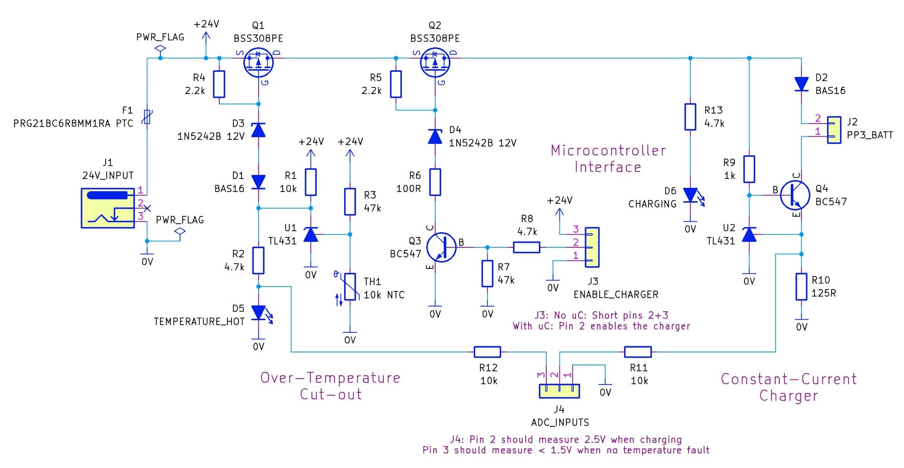
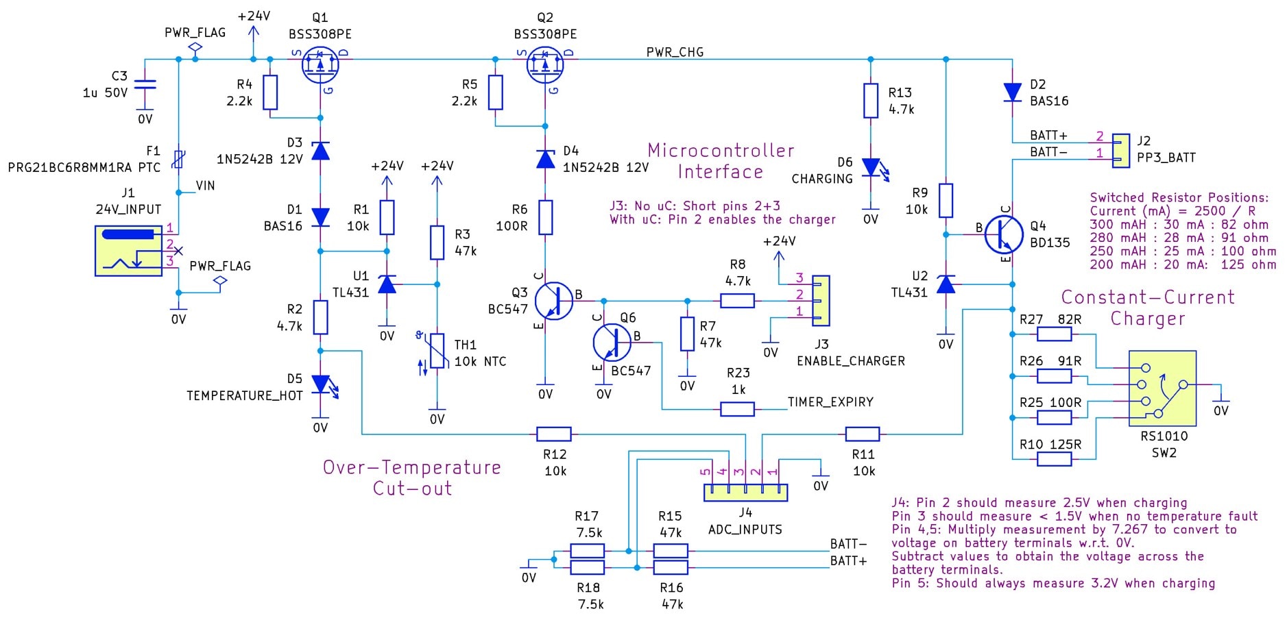
    I think the circuit below would do it. It's based off of a simpler charger here:  Smart Doorbell System – Part 6 – Chime Module Complete Circuit Design  and based on information from a battery mnfr PDF doc which specifies that it should be OK to charge at 0.1C for at least a day. 

    This circuit charges at 20 mA, and would take 15 hours to fully charge the battery. The battery would need to be manually disconnected within 24 hours. 

    However, there is also a microcontroller interface, so that you could turn it on/off based on a timer if desired (or any other logic circuit that can perform the timing).

    Without the microcontroller, you'd need to remember to disconnect after a day of charging. If you need a PCB for this, let me know (it's fairly easy for me to convert to a PCB, since I've already created the schematic in the same CAD software that would create the PCB).

    There's no guarantee that it will work, but it would be easy to test and then that would provide reasonable confidence with it (I'd trust this more than a cheap charger).

    image

    • Cancel
    • Vote Up +3 Vote Down
    • Sign in to reply
    • Verify Answer
    • Cancel
Reply
  • shabaz
    0 shabaz 11 months ago

    I think the circuit below would do it. It's based off of a simpler charger here:  Smart Doorbell System – Part 6 – Chime Module Complete Circuit Design  and based on information from a battery mnfr PDF doc which specifies that it should be OK to charge at 0.1C for at least a day. 

    This circuit charges at 20 mA, and would take 15 hours to fully charge the battery. The battery would need to be manually disconnected within 24 hours. 

    However, there is also a microcontroller interface, so that you could turn it on/off based on a timer if desired (or any other logic circuit that can perform the timing).

    Without the microcontroller, you'd need to remember to disconnect after a day of charging. If you need a PCB for this, let me know (it's fairly easy for me to convert to a PCB, since I've already created the schematic in the same CAD software that would create the PCB).

    There's no guarantee that it will work, but it would be easy to test and then that would provide reasonable confidence with it (I'd trust this more than a cheap charger).

    image

    • Cancel
    • Vote Up +3 Vote Down
    • Sign in to reply
    • Verify Answer
    • Cancel
Children
  • shabaz
    0 shabaz 11 months ago in reply to shabaz

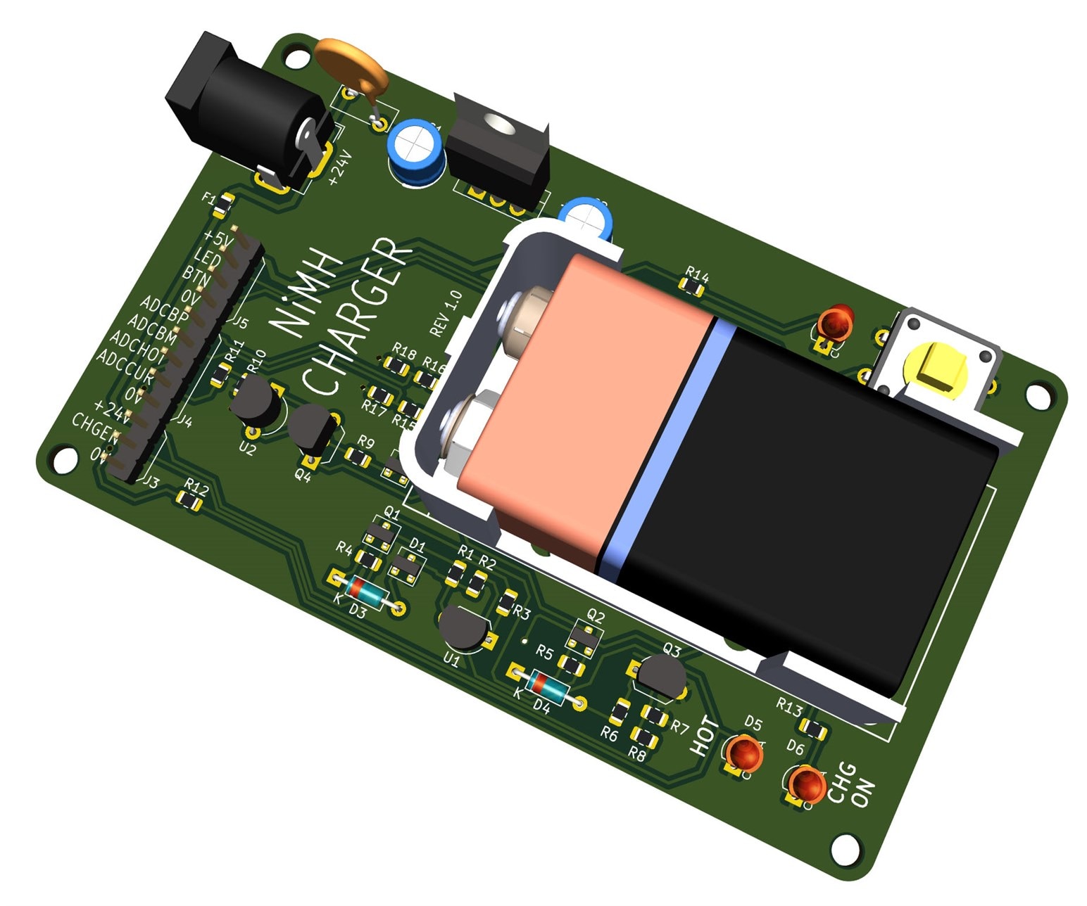
    I had some time, to lay out the PCB.  This board is 100 x 60 mm and several different PP3 battery holders will fit. All parts are jellybean. The optional microcontroller is connected to the row of pin-headers on the left side of the photo (without it, the user would need to disconnect after 24 hours as mentioned above).

    image

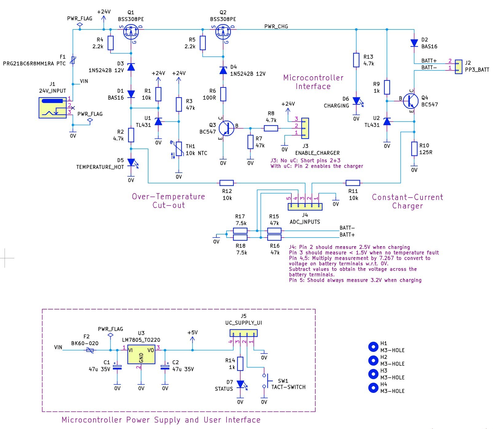
    This is the schematic:

    image

    I'll wait a day in case anyone spots any errors/major problems, and then I'll generate the Gerber files and place the project on GitHub. There's no guarantee it will work, but if anyone tries the circuit, please report back with any feedback/mods!

    • Cancel
    • Vote Up +5 Vote Down
    • Sign in to reply
    • Verify Answer
    • Cancel
  • genebren
    0 genebren 11 months ago in reply to shabaz

    Very Nice!  This is something that I would like to look into further in the future.  I really do appreciate your efforts to assist and to promote a true sense of community here on element14!

    • Cancel
    • Vote Up +3 Vote Down
    • Sign in to reply
    • Verify Answer
    • Cancel
  • koudelad
    0 koudelad 11 months ago in reply to shabaz

    Interesting, thank you for the inspiration.

    • Cancel
    • Vote Up +1 Vote Down
    • Sign in to reply
    • Verify Answer
    • Cancel
  • shabaz
    0 shabaz 10 months ago in reply to shabaz

    It was bugging me that there wasn't a timeout. I've been in the position where I've forgotten to unplug a charger.

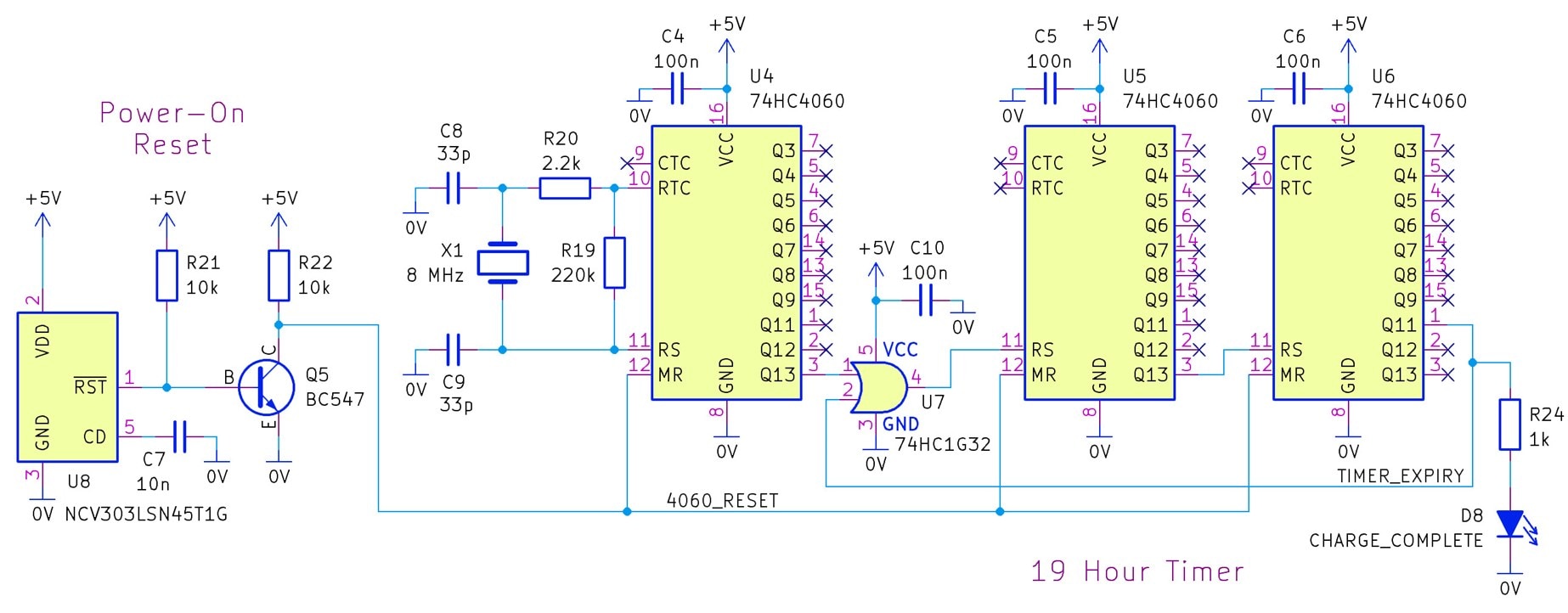
    The timer needs to be somewhere in the region of 16-24 hours. The design below (untested) uses a load of divider chips. It looks a lot, but 74HC4060 are cheap (and probably there's no size restriction). All parts here shouldn't cost more than a few $ total.

    The crystal output is just divided loads, and when 19 hours is reached, the TIMER_EXPIRY signal goes high, and that also prevents any more counting.

    image

    The timer isn't essential, and if there's a microcontroller attached, then it's redundant (unless such a hardware timer is preferred).

    The main circuit is tweaked to add the TIMER_EXPIRY connection as an input:

    image

    Also, while I was at it, I replaced the constant current resistor with a rotary selector, since it appears there are PP3 batteries with a range of capacity. Probably overkill to have such granularity, but the rotary switch could be replaced with a wire link to permanently set a current if desired.

    • Cancel
    • Vote Up +3 Vote Down
    • Sign in to reply
    • Verify Answer
    • Cancel
  • koudelad
    0 koudelad 10 months ago in reply to shabaz

    Thank you, but to be honest, I think a single 8-bit 6-pin MCU would replace the timing circuit and maybe also the charging logic.

    • Cancel
    • Vote Up +1 Vote Down
    • Sign in to reply
    • Verify Answer
    • Cancel
  • shabaz
    0 shabaz 10 months ago in reply to koudelad

    Yes, it would be greatly simplified with a microcontroller.

    I'll document the rest somewhere and maybe finish it if it helps anyone.

    I couldn't settle on a target microcontroller (and didn't fancy coding anything currently), so I figured I may as well make it microcontroller-agnostic, i.e., one could unpopulate those additions if the microcontroller interface is used.

    It's just a mental exercise, I have no serious suggestion for anyone to construct this unless they enjoy soldering a lot of parts. Plus, my design decisions won't be the same as others; I just used what parts I was familiar with (I'd already tested that constant-current portion in that Bluetooth project, so I lifted that as-is).

    • Cancel
    • Vote Up +2 Vote Down
    • Sign in to reply
    • Verify Answer
    • Cancel
element14 Community

element14 is the first online community specifically for engineers. Connect with your peers and get expert answers to your questions.

  • Members
  • Learn
  • Technologies
  • Challenges & Projects
  • Products
  • Store
  • About Us
  • Feedback & Support
  • FAQs
  • Terms of Use
  • Privacy Policy
  • Legal and Copyright Notices
  • Sitemap
  • Cookies

An Avnet Company © 2025 Premier Farnell Limited. All Rights Reserved.

Premier Farnell Ltd, registered in England and Wales (no 00876412), registered office: Farnell House, Forge Lane, Leeds LS12 2NE.

ICP 备案号 10220084.

Follow element14

  • X
  • Facebook
  • linkedin
  • YouTube