element14 Community
element14 Community
    Register Log In
  • Site
  • Search
  • Log In Register
  • Community Hub
    Community Hub
    • What's New on element14
    • Feedback and Support
    • Benefits of Membership
    • Personal Blogs
    • Members Area
    • Achievement Levels
  • Learn
    Learn
    • Ask an Expert
    • eBooks
    • element14 presents
    • Learning Center
    • Tech Spotlight
    • STEM Academy
    • Webinars, Training and Events
    • Learning Groups
  • Technologies
    Technologies
    • 3D Printing
    • FPGA
    • Industrial Automation
    • Internet of Things
    • Power & Energy
    • Sensors
    • Technology Groups
  • Challenges & Projects
    Challenges & Projects
    • Design Challenges
    • element14 presents Projects
    • Project14
    • Arduino Projects
    • Raspberry Pi Projects
    • Project Groups
  • Products
    Products
    • Arduino
    • Avnet & Tria Boards Community
    • Dev Tools
    • Manufacturers
    • Multicomp Pro
    • Product Groups
    • Raspberry Pi
    • RoadTests & Reviews
  • About Us
    About the element14 Community
  • Store
    Store
    • Visit Your Store
    • Choose another store...
      • Europe
      •  Austria (German)
      •  Belgium (Dutch, French)
      •  Bulgaria (Bulgarian)
      •  Czech Republic (Czech)
      •  Denmark (Danish)
      •  Estonia (Estonian)
      •  Finland (Finnish)
      •  France (French)
      •  Germany (German)
      •  Hungary (Hungarian)
      •  Ireland
      •  Israel
      •  Italy (Italian)
      •  Latvia (Latvian)
      •  
      •  Lithuania (Lithuanian)
      •  Netherlands (Dutch)
      •  Norway (Norwegian)
      •  Poland (Polish)
      •  Portugal (Portuguese)
      •  Romania (Romanian)
      •  Russia (Russian)
      •  Slovakia (Slovak)
      •  Slovenia (Slovenian)
      •  Spain (Spanish)
      •  Sweden (Swedish)
      •  Switzerland(German, French)
      •  Turkey (Turkish)
      •  United Kingdom
      • Asia Pacific
      •  Australia
      •  China
      •  Hong Kong
      •  India
      •  Japan
      •  Korea (Korean)
      •  Malaysia
      •  New Zealand
      •  Philippines
      •  Singapore
      •  Taiwan
      •  Thailand (Thai)
      •  Vietnam
      • Americas
      •  Brazil (Portuguese)
      •  Canada
      •  Mexico (Spanish)
      •  United States
      Can't find the country/region you're looking for? Visit our export site or find a local distributor.
  • Translate
  • Profile
  • Settings
Embedded and Microcontrollers
  • Technologies
  • More
Embedded and Microcontrollers
Embedded Forum Running a pic18F45K20 at full speed
  • Blog
  • Forum
  • Documents
  • Quiz
  • Polls
  • Files
  • Members
  • Mentions
  • Sub-Groups
  • Tags
  • More
  • Cancel
  • New
Join Embedded and Microcontrollers to participate - click to join for free!
Actions
  • Share
  • More
  • Cancel
Forum Thread Details
  • Replies 16 replies
  • Subscribers 502 subscribers
  • Views 1630 views
  • Users 0 members are here
  • i2c
  • pic18f45k20
  • ds1803
  • pics
Related

Running a pic18F45K20 at full speed

JohnDSiviter
JohnDSiviter over 15 years ago

Can anyone help with this simple problem, I want to achieve full speed 64MHz, at the moment I am getting 16MHz external, when I run a simple while loop (while(1){PORTD=0xFF;PORTD=0x00;}, I get a 4MHz squarewave, also I am having problems getting I2C working communicating with a DS1803E-010DS1803E-010 digital potentiometer:


#pragma config FOSC = INTIO7, FCMEN = OFF, IESO = OFF                       // CONFIG1H
#pragma config PWRT = ON, BOREN = OFF, BORV = 30                            // CONFIG2L
#pragma config WDTEN = OFF, WDTPS = 32768                                   // CONFIG2H
#pragma config MCLRE = OFF, LPT1OSC = OFF, PBADEN = OFF, CCP2MX = PORTC     // CONFIG3H
#pragma config STVREN = ON, LVP = OFF, XINST = OFF                          // CONFIG4L
#pragma config CP0 = OFF, CP1 = OFF, CP2 = OFF, CP3 = OFF                   // CONFIG5L
#pragma config CPB = OFF, CPD = OFF                                         // CONFIG5H
#pragma config WRT0 = OFF, WRT1 = OFF, WRT2 = OFF, WRT3 = OFF               // CONFIG6L
#pragma config WRTB = OFF, WRTC = OFF, WRTD = OFF                           // CONFIG6H
#pragma config EBTR0 = OFF, EBTR1 = OFF, EBTR2 = OFF, EBTR3 = OFF           // CONFIG7L
#pragma config EBTRB = OFF                                                  // CONFIG7H

/** I N C L U D E S **************************************************/
#include "p18f45k20.h"
#include "07 ADC.h"  // header file
#include "delays.h"
#include "spi.h"
#include "i2c.h"

//#include "math.h"
//#include "08 Interrupts.h"  // header file ****throws error

/** Prototypes**/
void main(void);
unsigned char I2C_SendByte(char myVolume);//char myByte)
unsigned char IncrementGrey(unsigned char Value); unsigned char DecrementGrey(unsigned char Value);
unsigned char WriteI2C1(  unsigned char data_out );
unsigned char ReadI2C1(  unsigned char data_out );
/** V A R I A B L E S *************************************************/
#pragma udata   // declare statically allocated uinitialized variables

/** D E C L A R A T I O N S *******************************************/
#pragma code    // declare executable instructions

/*******Global Variables******************/

/**********************************/
void main(void)
{
unsigned char count=1;
signed   char Direction_Up=-1;
unsigned char volume=0x00;
unsigned char PA=0x00;
unsigned char NAPA=0x00;
unsigned char greyCode=0x00;
unsigned char temp;
unsigned char PORTx;
/******************************************************************/
WDTCONbits.SWDTEN = 0; // Disable Watchdog
OSCTUNEbits.PLLEN    = 1; // Enable PLL //PLL enabled for INTOSC (4 MHz and 8 MHz only)

// IDLEN IRCF2 IRCF1 IRCF0 OSTS(1) IOFS SCS1 SCS0

OSCCONbits.IDLEN     = 0;    // Not enable pherimetral during sleep()
OSCCONbits.SCS1      = 1;    // Internal oscillator selected
OSCCONbits.SCS0      = 0;    //

OSCCONbits.IRCF2     = 1;    // 16 Mhz selected, 110=8Mhz
OSCCONbits.IRCF1     = 1;
OSCCONbits.IRCF0     = 1;

while(OSCCONbits.OSTS == 0){}       //Oscillator Start-up Time-out Status bit
while(OSCCONbits.IOFS == 0){}       //INTOSC Frequency Stable bit       
/******************************************************************/
    // Init I/O
    TRISC = TRISD = 0x00;      // PORTD bits 7:0 are all outputs (0)
    TRISB = 0xFF;  // PORTB (Encoder) are all inputs (1)
// TRISAbits.TRISA0 = 1;  // TRISA0 input

INTCON2bits.RBPU = 0;  // enable PORTB internal pullups
INTCON = 0b11100000;
INTCONbits.GIEL = 1;
INTCON2bits.INTEDG1 = 0;
INTCON3bits.INT1IP = 0;
INTCON3bits.INT1IE = 1;
INTCON3bits.INT1IF = 0;
//INTCON.PLLEN = 1;
RCONbits.IPEN = 1;

WPUBbits.WPUB0 = 1;   // enable pull up on RB0
    TRISBbits.TRISB0 = 1;       // PORTB bit 0 (connected to switch) is input (1)

PA=NAPA=PORTD=0;
volume=0xFF;PORTD=0xFF;
while(1)
{

PA=NAPA;
/* remove this after test */
while (!Switch_Pin1)
{
  Delay1KTCYx(50); //delay for switch debouncing - triggers lagging edge
  if (Switch_Pin1) {Delay1KTCYx(50);NAPA = IncrementGrey(NAPA);} //Increments PA on key release
}
/**************************/
// NAPA=PORTB;
if (PA!=NAPA)
{
  switch(NAPA)
  {

     case 0x00:
        switch (PA) //check last state
        {
         case 0x02:Direction_Up=1; break;
         case 0x01:Direction_Up=0; break;
         default:  Direction_Up=-1;break;
        }
      break;

      case 0x01:
        switch (PA)
        {
         case 0x00:Direction_Up=1; break;//TEMP STOP CODE break;
         case 0x03:Direction_Up=0; break;
         default:  Direction_Up=-1;break;
        }
      break;

     case 0x03:
        switch (PA)
        {
         case 0x01:Direction_Up=1; break;
         case 0x02:Direction_Up=0; break;
         default:  Direction_Up=-1;break;
        }
      break;
         
      case 0x02:
        switch (PA)
        {
         case 0x03: Direction_Up=1; break;   
         case 0x00: Direction_Up=0; break;
         default:   Direction_Up=-1;break;
        }
      default:break;
    
  }
}

switch (Direction_Up)
{
  case 1: volume++;PORTx = I2C_SendByte(volume);PORTD = volume;break;
    default: break;
  case 0: volume--;PORTx = I2C_SendByte(volume);PORTD = volume;break;
}

Direction_Up=-1;
} //while end

}


unsigned char I2C_SendByte(char myVolume)//char myByte)
{
unsigned char SPI_result=-1;
 
//• MSSP Control Register 1 (SSPCON1)
//• MSSP Control Register 2 (SSPCON2)
//• MSSP STATUS register (SSPSTAT)
//• Serial Receive/Transmit Buffer Register
//(SSPBUF)
//• MSSP Shift Register (SSPSR) – Not directly
//accessible
//• MSSP Address Register (SSPADD)
SSPSTAT = 0x80;//Disable SMBus & Slew Rate Control
SSPCON1 = 0x28; //Enable MSSP Master, SSPCON1=MASTER;
   // SPPADD must go after SSPCON1=MASTER; // ADD<7:0> = 1/Fi2c * FOSC-1 = 1/400,000 * 16,000 - 1 = 39 = 0010,0111b = 0x27
SSPCON2 = 0x00; //Clear Control Bits
//SSPADD = 0x18; //Should be 0x18 for 100kHz
SSPADD=0x27;//SCL pin clock period = ((ADD<7:0> + 1) *4)/FOSC
DDRCbits.RC3 = 1; //Configure SCL as Input
DDRCbits.RC4 = 1; //Configure SDA as Input
   //StartI2C();
   //OpenI2C(MASTER, SLEW_ON);
     SPI_result =WriteI2C(0b10100000);// 0101,address
     Delay1KTCYx(500);
  SPI_result =WriteI2C(myVolume);
  //Delay1KTCYx(500);
  return ReadI2C();
}


unsigned char IncrementGrey(unsigned char Value)
{
switch (Value)
{
   case 0x00:Value=0x01;break;
   case 0x01:Value=0x03;break;
   case 0x03:Value=0x02;break;
   case 0x02:Value=0x00;break;
   default:break;
}
return Value;
}
unsigned char DecrementGrey(unsigned char Value)
{
switch (Value)
{
   case 0x00:Value=0x02;break;
   case 0x01:Value=0x00;break;
   case 0x03:Value=0x01;break;
   case 0x02:Value=0x03;break;
   default:break;
}
return Value;
}

  • Sign in to reply
  • Cancel
  • e14 Contributor
    e14 Contributor over 15 years ago in reply to firatkocak

    If you're using the C18 compiler, inline assembly is done like this


    _asm
    /* User assembly code */
    MOVLW 10 // Move decimal 10 to count
    MOVWF count, 0
    /* Loop until count is 0 */
    start:
    DECFSZ count, 1, 0
    GOTO done
    BRA start
    done:
    _endasm

    _asm  /* User assembly code */ _endasm

    • Cancel
    • Vote Up 0 Vote Down
    • Sign in to reply
    • Cancel
  • JohnDSiviter
    JohnDSiviter over 15 years ago in reply to e14 Contributor

    Thanks all, and thanks Brennanthi I will try that later.

    • Cancel
    • Vote Up 0 Vote Down
    • Sign in to reply
    • Cancel
  • JohnDSiviter
    JohnDSiviter over 15 years ago in reply to JohnDSiviter

    My latest code (good for anyone learning the PIC18F45K20), I have also copied the descriptions for the status registers in there, the code is purposely bulky by switching invividual bits in the status register, but I like it that way when learning these PICs:


    /** C O N F I G U R A T I O N   B I T S ******************************/

    #pragma config FOSC = INTIO7, FCMEN = OFF, IESO = OFF                       // CONFIG1H, FSOC=HSPLL, INTIO67
    #pragma config PWRT = ON, BOREN = OFF, BORV = 30                            // CONFIG2L
    #pragma config WDTEN = OFF, WDTPS = 1                                       // CONFIG2H
    #pragma config MCLRE = OFF, LPT1OSC = OFF, PBADEN = OFF, CCP2MX = PORTC     // CONFIG3H
    #pragma config STVREN = ON, LVP = OFF, XINST = OFF                          // CONFIG4L
    #pragma config CP0 = OFF, CP1 = OFF, CP2 = OFF, CP3 = OFF                   // CONFIG5L
    #pragma config CPB = OFF, CPD = OFF                                         // CONFIG5H
    #pragma config WRT0 = OFF, WRT1 = OFF, WRT2 = OFF, WRT3 = OFF               // CONFIG6L
    #pragma config WRTB = OFF, WRTC = OFF, WRTD = OFF                           // CONFIG6H
    #pragma config EBTR0 = OFF, EBTR1 = OFF, EBTR2 = OFF, EBTR3 = OFF           // CONFIG7L
    #pragma config EBTRB = OFF                                                  // CONFIG7H

    /** I N C L U D E S **************************************************/
    #include "p18f45k20.h"
    #include "myLibrary.h"  // header file
    #include "delays.h"
    #include "i2c.h"
    #include "spi.h"

    //#include "math.h"

    /** Prototypes*********************************************************/
    void          main(void);
    void        I2C_DS1803_SendByte(char myVolume);//char myByte)
    unsigned char I2C_DS1803_RecieveByte(signed char myVolume);//char myByte);
    unsigned char IncrementGrey(unsigned char Value); unsigned char DecrementGrey(unsigned char Value);
    unsigned char EEPROM_Read(unsigned char address);void EEPROM_Write(unsigned char address, unsigned char databyte);
    unsigned char myI2CWriteByte(unsigned char myByte);
    signed char returnVolumeFromGrey(unsigned char PresentState, unsigned char NextState, signed char myvolume);
    unsigned char ifSwitchIncNAPA(unsigned char SwitchPin, unsigned char NAPA);
    /** Interupt Prototypes ***********************************************/
    void interrupt_at_high_vector(void);
    void high_isr(void);

    /** V A R I A B L E S *************************************************/
    #pragma udata   // declare statically allocated uinitialized variables

    /** Interrupts ********************************************************/
    #pragma code high_vector=0x08
    void interrupt_at_high_vector(void)
    {
      _asm GOTO high_isr _endasm
    }

    #pragma code /* return to the default code section */

    #pragma interrupt high_isr
    void high_isr(void)
    {
    // This is where we keep the service routine, remember to set the config
        LATC = 1; //RC0 HIGH
        INTCONbits.TMR0IF = 0; //CLEAR TMR0 INT FLAG
    }
    //#pragma stack 0x300 0xff // set 64 byte stack at 0x300, needed by sdcc
    /***********************************************************************/
    void main(void)
    {
    // User Variables
    signed   char volume=0xFF;
    unsigned char PA=0x00;
    unsigned char NAPA=0x00;
    unsigned char temp;
    unsigned char PORTx;
    unsigned char save_me = 'x';
        unsigned char from_eeprom;
        // User Init I/O
        TRISD = 0x00;                      // PORTD bits 7:0 are all outputs (0)
        TRISB = 0xFF;                     // PORTB (Encoder) are all inputs (1)
    TRISC = 0xFF;
    DDRCbits.RC3 = 1;                  //Configure SCL as Output
    DDRCbits.RC4 = 1;                  //Configure SDA as Output
        /********************************************************************************** CPU Clocking ********************************************/
       
    //OSCCON***************** IDLEN IRCF2 IRCF1 IRCF0 OSTS(1) IOFS SCS1 SCS0
    OSCCONbits.IDLEN     = 0;    // Not enable pherimetral during sleep()
    OSCCONbits.IRCF2     = 1;    // 111=16 Mhz selected, 110=8Mhz
    OSCCONbits.IRCF1     = 1;
    OSCCONbits.IRCF0     = 1;
    OSCCONbits.SCS0      = 0; //  // Internal oscillator selected Internal 1X: Secondary 01:Primary:00
    OSCCONbits.SCS1      = 0;
    //Clock Status bits:
    while(OSCCONbits.OSTS == 0){}       //Oscillator Start-up Time-out Status bit
    while(OSCCONbits.IOFS == 0){}       //INTOSC Frequency Stable bit  
    WDTCONbits.SWDTEN    = 0;           // Disable Watchdog


    // OSCTUNE*************** INTSRC — — TUN4 TUN3 TUN2 TUN1 TUN0
    OSCTUNEbits.TUN0  = 1;
    OSCTUNEbits.TUN1  = 1;
    OSCTUNEbits.TUN2  = 1;
    OSCTUNEbits.TUN3  = 1;
    OSCTUNEbits.TUN4  = 0;
    /*
    bit 4-0 TUN4:TUN0: Frequency Tuning bits
      01111 = Maximum frequency
      • •
      • •
      00001
      00000 = Center frequency. Oscillator module is running at the calibrated frequency.
      11111
      • •
      • •
      10000 = Minimum frequency */

    OSCTUNEbits.PLLEN = 1;              // Enable PLL //PLL enabled for INTOSC (4 MHz and 8 MHz only)
    OSCTUNEbits.INTSRC= 1;              // PLL for 31khz option when selected
      //(SCS)System clock select bits:
     
       //
    //scs: 00 = Primary clock (determined by CONFIG1H[FOSC<3:0>]).
        /********************************************************************************** Interrupt Control ***************************************/   
    // INTCON  **************** GIE/GIEH PEIE/GIEL TMR0IE INT0IE RBIE TMR0IF INT0IF RBIF
    INTCONbits.GIE      = 0;    // Global Interrupt Enable bit:        1 = Enables all unmasked interrupts, 0 = Disables all interrupts
    INTCONbits.GIEL     = 0;     // PEIE/GIEL: Peripheral Interrupt Enable bit: When IPEN = 0:,   1 = Enables all unmasked peripheral interrupts, 0 = Disables all peripheral interrupts
    INTCONbits.TMR0IE   = 0;       // TMR0IE: TMR0 Overflow Interrupt Enable bit
    INTCONbits.INT0IE   = 0;       // INT0IE: INT0 External Interrupt Enable bit
    INTCONbits.RBIE     = 0;     // RBIE: RB Port Change Interrupt Enable bit
    INTCONbits.TMR0IF   = 0;       // TMR0IF: TMR0 Overflow Interrupt Flag bit
    INTCONbits.INT0IF   = 0;       // INT0IF: INT0 External Interrupt Flag bit
    INTCONbits.RBIF     = 0;       // RBIF: RB Port Change Interrupt Flag bit


    // INTCON2 **************** RBPU INTEDG0 INTEDG1 INTEDG2 — TMR0IP — RBIP 
    INTCON2bits.RBPU     = 1;    // RBPU: 'PORTB Pull-up Enable bit
    INTCON2bits.INTEDG0  = 0;      // INTEDG0: External Interrupt 0 Edge Select bit, 1 = Interrupt on rising edge, 0 = Interrupt on falling edge   
    INTCON2bits.INTEDG1  = 0;      // INTEDG1: External Interrupt 1 Edge Select bit, 1 = Interrupt on rising edge, 0 = Interrupt on falling edge
    INTCON2bits.INTEDG2  = 0;      // INTEDG2: External Interrupt 2 Edge Select bit, 1 = Interrupt on rising edge, 0 = Interrupt on falling edge
    INTCON2bits.TMR0IP   = 0;      // TMR0IP: TMR0 Overflow Interrupt Priority bit , 1 = High priority           , 0 = Low priority
    INTCON2bits.RBIP     = 0;      // RBIP: RB Port Change Interrupt Priority bit  , 1 = High priority           , 0 = Low priority


    // INTCON3 **************** INT2IP INT1IP — INT2IE INT1IE — INT2IF INT1IF
    INTCON3bits.INT2IP  = 0;       // INT2IP: INT2 External Interrupt Priority bit , 1 = High priority           , 0 = Low priority
    INTCON3bits.INT1IP  = 0;       // INT1IP: INT1 External Interrupt Priority bit , 1 = High priority           , 0 = Low priority
      //bit 5 unimplemented Read as '0'
    INTCON3bits.INT2IE  = 0;       // INT2IE: INT2 External Interrupt Enable bit   , 1 = Enables the INT2 external interrupt
    INTCON3bits.INT1IE  = 0;       // INT1IE: INT1 External Interrupt Enable bit   , 1 = Enables the INT1 external interrupt
    INTCON3bits.INT2IF  = 0;       // INT2IF: INT2 External Interrupt Flag bit     , 1 = The INT2 external interrupt occurred (must be cleared in software)
    INTCON3bits.INT1IF  = 0;       // INT1 External Interrupt Flag bit             , 1 = The INT1 external interrupt occurred (must be cleared in software)
    RCONbits.IPEN = 1;

    WPUBbits.WPUB0 = 1;           // enable pull up on RB0
    /********************************************************************************** MSSP Control ***************************************/   
    /***************I2C Setup*********************************************/
    //SSPCON - Control Register, SSPSTAT - Status Register,
    //*********************SSPCON1............ WCOL SSPOV SSPEN CKP SSPM3 SSPM2 SSPM1 SSPM0
    SSPCON1bits.WCOL    = 0;    //*      // WCOL: Write Collision Detect bit (Transmit mode only), 1 = The SSPBUF register is written while it is still transmitting the previous word (must be cleared in software)
    SSPCON1bits.SSPOV   = 0;             // SSPOV: Receive Overflow Indicator bit, only for spi slave mode
    SSPCON1bits.SSPEN   = 1;    //*      // 1 = SSPEN; Enables the serial port and configures the SDA and SCL pins as the serial port pins
    SSPCON1bits.CKP     = 0;    //*      // Write Collision Detect bit = OFF
    SSPCON1bits.SSPM3   = 1;             // 1000 = I2C Master mode, clock = FOSC/(4 * (SSPADD + 1))
    SSPCON1bits.SSPM2   = 0;             //
    SSPCON1bits.SSPM1   = 0;             //
    SSPCON1bits.SSPM0   = 0;             //
    /*
    bit 3-0 SSPM3:SSPM0: Synchronous Serial Port Mode Select bits
    1111 = I2C Slave mode, 10-bit address with Start and Stop bit interrupts enabled
    1110 = I2C Slave mode, 7-bit address with Start and Stop bit interrupts enabled
    1011 = I2C Firmware Controlled Master mode (Slave Idle)
    1000 = I2C Master mode, clock = FOSC/(4 * (SSPADD + 1))
    0111 = I2C Slave mode, 10-bit address
    0110 = I2C Slave mode, 7-bit address
    */
        // SPPADD must go after SSPCON1=MASTER; // ADD<7:0> = 1/Fi2c * FOSC-1 = 1/400,000 * 16,000 - 1 = 39 = 0010,0111b = 0x27
    // SSPCON2 = 0x00; //Clear Control Bits, GCEN ACKSTAT ACKDT ACKEN(1) RCEN(1) PEN(1) RSEN(1) SEN(1)


    SSPCON2bits.SEN    = 1;     // *        // Start Condition Enabled/Stretch Enabled bit(1) *try toggling
    SSPCON2bits.PEN    = 1;     // *        // Stop Condition Enable bit (Master mode only)(1) ****
    SSPCON2bits.RCEN   = 0;     // *        // Receive Enable bit (Master mode only)(1)
    SSPCON2bits.ACKEN  = 0;     // *        // Acknowledge Sequence Enable bit (Master Receive mode only)(1) #####
    SSPCON2bits.ACKDT  = 0;     // *        // Acknowledge Data bit (Master Receive mode only) #####
    SSPCON2bits.ACKSTAT= 0;     // *        // Acknowledge Status bit (Master Transmit mode only) %%%%%
    SSPCON2bits.GCEN   = 0;                 // General Call Enable bit (Slave mode only), 0 = General call address disabled
    //SSPADD = 0x18; //Should be 0x18 for 100kHz


    //*********************SSPSTAT............ SMP CKE D/A P S R/W UA BF
    SSPSTATbits.SMP    = 0;               // SMP: Slew Rate Control bit, 1 = Slew rate control disabled for Standard Speed mode (100 kHz and 1 MHz), 0 = Slew rate control enabled for High-Speed mode (400 kHz)
    SSPSTATbits.CKE    = 0;      // CKE: SMBus Select bit, 1 = Enable SMBus specific inputs, 0 = Disable SMBus specific inputs
    SSPSTATbits.D      = 0;      // D/A: Data/Address bit, for slave mode, 1 = Indicates that the last byte received or transmitted was data, 0 = address
    SSPSTATbits.P      = 0;      // P: Stop bit, 1 = Indicates that a Stop bit has been detected last
    SSPSTATbits.S      = 0;      // S: Start bit, 1 = Indicates that a Start bit has been detected last
    SSPSTATbits.R      = 0;      // R/`W: Read/Write bit Information (I2C mode only),slave (1=read, 0=write), master (1=transmit in progress, 0=transmit not in progress).
    SSPSTATbits.UA     = 0;      // UA: Update Address bit (10-bit Slave mode only), 1 = Indicates that the user needs to update the address in the SSPADD register, 0 = Address does not need to be updated
    SSPSTATbits.BF     = 0;      // BF: Buffer Full Status bit, 'In Transmit mode'(1 = Receive complete, SSPBUF is full, 0 = Receive not complete, SSPBUF is empty), 'In Receive mode:'(1 = Data transmit in progress (does not include the 'ACK and Stop bits), SSPBUF is full,0 = Data transmit complete (does not include the 'ACK and Stop bits), SSPBUF is empty).


    SSPADD=0x27;                          //SCL pin clock period = ((ADD<7:0> + 1) *4)/FOSC


    //********************** ANSEL............. ANS7(1) ANS6(1) ANS5(1) ANS4 ANS3 ANS2 ANS1 ANS0


    /*********************************************************************/
    PA=NAPA=PORTD=0;
    volume=0x30;PORTD=0x00;
        /********************************   MAIN LOOP   ****************************************************************************************/
    while(1)
    {
      PA=NAPA; /* remove this after test */
      //NAPA   = ifSwitchIncNAPA      (Switch_Pin1, NAPA  );
      while (!Switch_Pin1)
      {
       Delay1KTCYx(50); //delay for switch debouncing - triggers lagging edge
       if (Switch_Pin1) {NAPA = IncrementGrey(NAPA);} //Increments PA on key release
       I2C_DS1803_SendByte(volume);
      }
      volume = returnVolumeFromGrey (PA, NAPA   , volume);
            Delay1KTCYx(50);PORTD=volume;
     
     
    }
    //EEPROM_Write(0x7000, 12354);
    //PORTD = EEPROM_Read(0x7000);
    }
        /********************************   MAIN LOOP   ****************************************************************************************/
       
       
    /******************************** FUNCTIONS ************************************************************************************************/
    void I2C_DS1803_SendByte(signed char myVolume)//char myByte)
    {
            TRISC = 0x00; //turn on tri-state register and
                          //make all output pins
            //PORTC = 0x00; //make all output pins LOW

            OpenI2C( MASTER, SLEW_OFF);
            SSPADD = 0x27;//0x33;
      StartI2C();                     // Sends start bits
          WriteI2C(0b01010000);       // Address
          WriteI2C(0b10101111);       // Command: write to both potentiometers
       WriteI2C(0b00110101);  // Value
      IdleI2C ();
    }
    unsigned char I2C_DS1803_RecieveByte(signed char myVolume)//char myByte)
    {
    unsigned char R1, R2;
            TRISC = 0x00; //turn on tri-state register and
                          //make all output pins
            PORTC = 0x00; //make all output pins LOW

            OpenI2C( MASTER, SLEW_OFF);
            SSPADD = 0x3F;
        AckI2C();IdleI2C ();
    StartI2C();                         // Sends start bits
    AckI2C();IdleI2C ();
    WriteI2C(0b01010000);               // Address
    AckI2C();IdleI2C ();
    R1 = ReadI2C();
    AckI2C();IdleI2C ();
    R2 = ReadI2C();
    AckI2C();IdleI2C ();
        Delay1KTCYx(500);
    return R1;                   // Value
    }


    unsigned char IncrementGrey(unsigned char Value)
    {
    switch (Value)
    {
       case 0x00:Value=0x01;break;
       case 0x01:Value=0x03;break;
       case 0x03:Value=0x02;break;
       case 0x02:Value=0x00;break;
       default:break;
    }
    return Value;
    }
    unsigned char DecrementGrey(unsigned char Value)
    {
    switch (Value)
    {
       case 0x00:Value=0x02;break;
       case 0x01:Value=0x00;break;
       case 0x03:Value=0x01;break;
       case 0x02:Value=0x03;break;
       default:break;
    }
    return Value;
    }


    unsigned char EEPROM_Read(unsigned char address)
    { // reads and returns the EEPROM byte value at the address given
    // given in "address".
    EECON1bits.EEPGD = 0;// Set toaccessEEPROMmemory
    EECON1bits.CFGS= 0;// Do notaccessConfigregisters
    EEADR = address;//Load EEADRwith address of location to write.
    // execute the read
    EECON1bits.RD = 1;//Set the RDbit to execute the EEPROM read
    //The value read is ready the next instruction cycle in EEDATA. No wait is
    //needed.
    return EEDATA;
    }


    void EEPROM_Write(unsigned char address, unsigned char databyte)
    { // writes the "databyte" value to EEPROM at the address given
    // location in "address".
    EECON1bits.EEPGD = 0; // Set to access EEPROM memory
    EECON1bits.CFGS = 0; // Do not access Config registers
    EEDATA = databyte; // Load EEDATA with byte to be written
    EEADR = address; // Load EEADR with address of location to write.
    EECON1bits.WREN = 1; // Enable writing
    INTCONbits.GIE = 0; // Disable interrupts
    EECON2 = 0x55; // Begin Write sequence
    EECON2 = 0xAA;
    EECON1bits.WR = 1; // Set WR bit to begin EEPROM write
    INTCONbits.GIE = 1; // re-enable interrupts
    while (EECON1bits.WR == 1)
    { // wait for write to complete.
    };
    EECON1bits.WREN = 0;
    }


    signed char returnVolumeFromGrey(unsigned char PA, unsigned char NAPA, signed char myvolume)
    {
      if (PA!=NAPA)
      {
       switch(NAPA)
       {
          case 0x00:
            switch (PA) //check last state
            {
             case 0x02:myvolume++; break;
             case 0x01:myvolume--; break;
            }
           break;

           case 0x01:
            switch (PA)
            {
             case 0x00:myvolume++; break;
             case 0x03:myvolume--; break;
            }
           break;

          case 0x03:
            switch (PA)
            {
             case 0x01:myvolume++; break;
             case 0x02:myvolume--; break;
            }
           break;
             
           case 0x02:
            switch (PA)
            {
             case 0x03: myvolume++; break;   
             case 0x00: myvolume--; break;
            }
           default:break;
       }

      }
    return myvolume;
    } 
    unsigned char ifSwitchIncNAPA(unsigned char SwitchPin, unsigned char NAPA)
    {
      while (!Switch_Pin1)
      {
       Delay1KTCYx(50); //delay for switch debouncing - triggers lagging edge
       if (Switch_Pin1) {NAPA = IncrementGrey(NAPA);} //Increments PA on key release
      }
    }

    • Cancel
    • Vote Up 0 Vote Down
    • Sign in to reply
    • Cancel
  • JohnDSiviter
    JohnDSiviter over 15 years ago in reply to JohnDSiviter

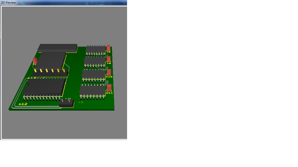
    I started designing the PCB, I like NI's Electronic workbench 3D representation, all fits on a 4cm x 4cm board (needs a few connectors on there and a few op-amps): image

    • Cancel
    • Vote Up 0 Vote Down
    • Sign in to reply
    • Cancel
  • JohnDSiviter
    JohnDSiviter over 15 years ago in reply to JohnDSiviter

    Ignore above, in my MCU discovery I have decided the 18F is too lowly a beast and have migrated onto the dsPIC33, wooed by its DSP charms and simplicity.

    • Cancel
    • Vote Up 0 Vote Down
    • Sign in to reply
    • Cancel
  • e14 Contributor
    e14 Contributor over 15 years ago in reply to JohnDSiviter

    I figured that was going to be the case but I didn't want to lead you in a different direction.

    • Cancel
    • Vote Up 0 Vote Down
    • Sign in to reply
    • Cancel
<
element14 Community

element14 is the first online community specifically for engineers. Connect with your peers and get expert answers to your questions.

  • Members
  • Learn
  • Technologies
  • Challenges & Projects
  • Products
  • Store
  • About Us
  • Feedback & Support
  • FAQs
  • Terms of Use
  • Privacy Policy
  • Legal and Copyright Notices
  • Sitemap
  • Cookies

An Avnet Company © 2026 Premier Farnell Limited. All Rights Reserved.

Premier Farnell Ltd, registered in England and Wales (no 00876412), registered office: Farnell House, Forge Lane, Leeds LS12 2NE.

Follow element14

  • X
  • Facebook
  • linkedin
  • YouTube