What is a sensor connector?

Various sensing technologies, such as sensors, switches, transducers, and other related devices, use sensor connectors to establish connections. Sensor connectors enable accurate data transfer in the form of signals from the sensor to the connected device with minimal loss or interference. The size, design, pin layouts, material, shape, lengths, and specifications of these connectors depend on the sensor type and the specific application.
What is a sensor connector used for?
In simple terms, sensor connectors link switches, sensors, and equipment with corresponding cables and components involved in industrial automation. All these discrete elements connect to form a single, highly efficient, automated unit. Such a unit operates at maximum productivity, enhances efficiency, and minimizes downtime.
The versatility of sensor connectors allows them to work with various switches and sensors across diverse industries and sectors. They are ubiquitous in industrial automation and process control applications, particularly within manufacturing and food and beverage industries.
What types of sensor connectors exist?
Sensor connectors can be classified according to their mating type:
Circular Connectors
A circular sensor connector is designed to withstand harsh environments. It is a cylindrical, multi-pin electrical connector with contacts that power sensors and transmit data or electrical signals. The most common types of circular connectors are:
- BNC Connectors: The Bayonet Neill–Concelman (BNC) connector is a miniature quick connect or disconnect radio frequency connector. The female connector has two bayonet lugs, and mating requires a quarter turn of the coupling nut. The coupling mechanism of the BNC connector allows quick connection and disconnection with positive locking.
- Threaded Connectors: A threaded connector allows users to screw in the connector to establish a secure connection between the sensor and other devices. The threaded construction ensures a secure fit and eliminates accidental disconnections. Threaded connectors are appropriate for applications that require stability and vibration tolerance. These connectors are also suitable for applications that work in and be immune to harsh environments.
- Push-Pull connectors: Push-Pull connectors are designed for quick and easy installation. These connectors have an internal locking mechanism that facilitates a robust and secure connection. Push-Pull connectors are easy to connect and disengage, which makes them suitable for hard-to-reach locations.
Rectangular Connectors
The compact design and high reliability of rectangular connectors make them popular in automotive and industrial applications. These connectors ensure optimal signal integrity in applications having limited internal space. Common types of rectangular connectors include:
- Board-to-board connectors: Board-to-board connectors connect multiple PCBs together without the need for a cable. Additional space for a cable is not necessary, making them suitable for space-constrained systems. These connectors are compatible with various PCB orientations, relative distances, and space limitations for design flexibility.
- Wire-to-Board Connectors: Wire-to-Board Connectors are common in complex electromechanical systems, such as drones and robots.
When would you choose each type of sensor connector?
The following key factors must be considered when choosing a suitable connector for any application:
- Connector Material: The properties of the material, such as strength, durability, and resistance to corrosion, influence its choice as connector material. The material should also be appropriate for the environment where the connector will be used. For example, brass connectors are more wear-resistant and have longer lifecycles, while aluminum connectors are lighter in weight. Plastics are suitable for limited reuse and disposable applications. Stainless steel works well for corrosive environments or some food industry applications.
- Space Constraints: The size and weight of cables and connectors must be reduced when available space is limited. Additionally, when dealing with difficult-to-reach areas, it is necessary to consider the frequency of connection, disconnection, and the ability to connect the two ends. The degree of stress to which the connectors are subjected is an important parameter.
- Number of Contacts: The type of sensor and the amount of data to be transferred determine the number of contacts required for the connectors.
- Termination methods: Termination method directly affects the assembly process and the ability to seal a connector. The two most common types of contact termination are crimping and soldering. Connectors with solder contacts are typically easier to seal against moisture ingress, while crimp contacts may offer better field repairability. Durability of the termination method is also an important consideration. Crimping is popular with wire-to-board and wire-to-wire connectors, while soldering is often used for board-to-board connectors.
- Ingress Protection: Sensor connectors must be protected from harsh operating environments. The Ingress Protection (IP) rating informs the protection of the connector against factors like water, dust, oils, and other contaminants.
Sensor and Actuator Connector Types for Industrial Environment
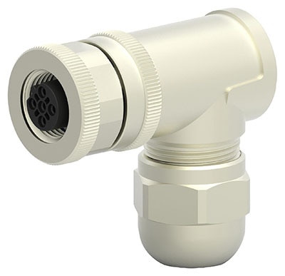
M8 connector: M8 connectors are widely used with industrial sensors, actuators, and other automation and control systems devices. These compact, robustly designed connectors provide a secure and reliable connection in demanding environments having moisture, dust, and other contaminants. M8 connectors come in various configurations, including male and female versions with different numbers of pins or contacts. They are commonly used with PLCs, I/O boxes, food and beverage processing, machine building, rubber and plastics, textile and printing presses, and HVAC systems.

Figure 1: M8 Connector (Source: TE connectivity)
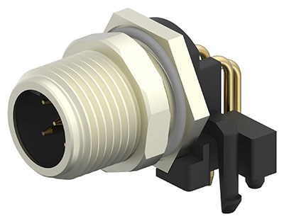
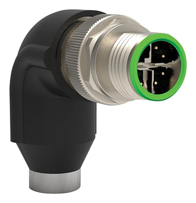
M12 connector: The circular M12 connector has a 12-mm locking thread designed for harsh and extreme environments. The connector has multiple pin count options specially designed for industrial automation applications. M12 connectors are used in agriculture, communications, plant automation, instrumentation and control, robotics, and transportation.

Figure 2: M12 Connector
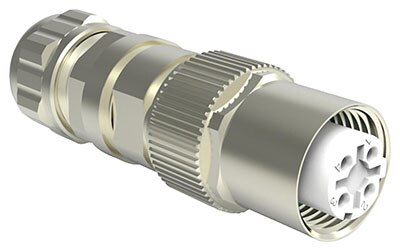
Circular Plastic Connectors (CPC): Connector contacts can be accurately aligned using polarized CPCs. They provide safe and reliable transmission of signals and power. CPCs are built with stabilized, heat-resistant thermoplastic material with self-extinguishing properties and find use in industrial automation, transportation, HVAC, building automation, medical, instrumentation, and defense systems. CPC contacts are detachable, and the technician can quickly replace the coupling ring for easy field maintenance.

Figure 3: Circular Plastic Connectors (CPC) Connector
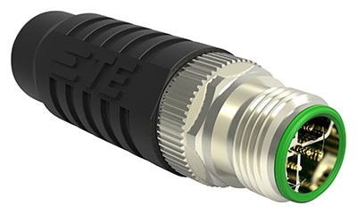
Dynamic Connectors: Dynamic connectors, from TE Connectivity, are designed to transmit signals and power. They are well-suited for industrial process control, human machine interfaces (HMI), motors, and robotics applications. There are several types of connectors in the Dynamic series, including wire-to-board, wire-to-panel, and wire-to-wire connectors with diverse housings available for most applications. Standard crimp and spring clamp variations of parts are available. Standardized contacts limit the amount of application tooling required.

Figure 4: Dynamic Series Connector
What are the different types of coding systems used for M12 connectors?
When choosing a cable for an application, selecting the correct size, length, number of connectors, pinout, and codes is critical. M12 cables come in various coding options, with each code designated for a particular application. Such coding prevents incorrect mating of products. The most common types of coding are:
- A-coded connectors are used as actuator-sensor plug connections for DeviceNet, IO-Link, and Profibus. A-coded connectors can vary in their number of pins, between 3 to 12 (more in some cases).
- B-coded connectors are primarily used in Fieldbus connections for Profibus and Interbus devices. B-coded connectors typically use three and five pins.
- D-coded connectors are used in network cables for Industrial Ethernet, Profinet, Ethernet/IP, and EtherCAT systems. These connectors can transfer data in real-time up to 100 Mbps. D-coded connectors typically have three to five pins.
- S-coded connectors have three or four pins and are designed for AC power supplies. They typically have a rated voltage of 630VAC and a rated current of 12A. S-coded connectors are ideal for motors, frequency-convertors, and motor-operated switches.
- T-coded connectors are designed for DC power connections. They have four pins with a rated current of 12A at 63 VDC. T-coded connectors are ideal for field bus applications, passive distribution boxes, and motors.

Figure 5: Coding systems for M12 connectors
How is power transmitted with a sensor connector?
Figure 6 illustrates power being transmitted with sensor connectors and cables using 4 to 20mA DC. A loop-powered transmitter, also known as a two-wire transmitter, is in position near the measurement point. The transmitter receives power from a 24VDC source in the control room. A load resistor is connected from the analog input to the ground. If the controller's analog input is configured to receive 0 to 5VDC, a 250Ω load resistor should be used. The voltage at the input will be 1V at 5mA and 5V at 20mA, with the transmitter having at least 19V available at its terminals. The current is transmitted using a sensor cable and connector.
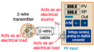
Figure 6: Power transmission with sensor connector (Source: control.com)
What is IO-Link?
IO-Link is a manufacturer-independent digital communication protocol/interface enabling communication among automation systems, sensors, and devices. A point-to-point interface connects sensors and actuators to a control system. The bi-directional and point-to-point features of IO-Link support its superior performance in a digital environment.
Users can take advantage of a 20-meter-long, unscreened 3-wire cable to establish a connection between the IO-Link controller and the device. The wiring is standard and based on M5, M8, and M12 connectors. Most IO-Link devices are armed with M12 connectors that can be used without restrictions for IO-Link's switching and communication modes.
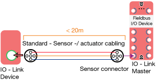
Figure 7: IO-Link structure (Source: electricalvolt.com)
Explain IP ratings regarding sensor connectors.
Sensor connectors commonly have ratings ranging from IP65 to IP69K. An IP65 rating safeguards against low-pressure water jets from any direction for up to one minute, allowing minimal liquid entry. IP66 represents protection against forceful jets from all angles for one minute, with restricted ingress. IP67 protects against submersion at a depth of between 15-1000 cm for 30 minutes. IP68 guarantees the ability to endure continuous submersion in water without water ingress, following manufacturer-specified conditions. IP69K is a specialized classification for devices subjected to high-pressure and high-temperature wash-downs. The 'K' suffix indicates the sensor connector's capability to endure direct exposure to exceedingly high-pressure water jets.
What accessories are available with sensor connectors?
Sensor connectors are essential components that connect sensors to other devices or systems. The following accessories are available for sensor connectors depending on the specific application:
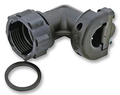
- Connector Backshells: A backshell protects the device from environment-related degradation by sealing the connector and cable termination point from moisture and dust. Connector backshells are fixed to the rear side of circular connectors. A backshell can also provide electromagnetic and radio frequency interference protection in conjunction with a shielded cable or wire braid.
- Connector Savers: The reliability of connectors gradually decreases with time. Soft contact metals (like gold) gradually wear away (wiping) with constant mating and demating. Connector Savers are used to offset such loss of reliability due to repeated mating. They are short, male/female adapters of identical types to the sensor connectors.
- Connector Strain Relief: Cables typically experience stress when bent or subjected to continuous back-and-forth movement. A strain relief or cable gland is employed to anchor the cable within the connector to address these issues. Strain relief prevents the propagation of external tensile and bending forces as the strain is absorbed by the structure on which the strain relief is mounted.
- Connector seals: Connector seals protect connectors from the operating environment. The environmental seal consists of a durable material, often high-quality rubber or plastic, and is positioned inside the connector between the mating surfaces or as cable entry shields between the connector and the cable. Its purpose is to obstruct the migration of contaminants along the cable into the connector.
Sensor Connector Solutions from TE Connectivity
TE Connectivity offers a variety of sensor connectors across various industries and applications.
Frequently Asked Questions
How do you install a sensor connector?
Installing a sensor connector involves properly connecting the wires or cables from a sensor to the corresponding pins or terminals of the connector. The steps can vary depending on the type of sensor, the connector design, and the specific application. These are the general steps for installing a sensor connector; however, for any connector, it is important to refer to the manufacturer’s documentation.
Prepare the Wires: If the sensor wires have insulation, strip a small portion of insulation from the ends to expose the conductors. Make sure the exposed length is appropriate for connecting to the connector.
Prepare the Connector: Open the connector housing, if applicable. Some connectors have a hinged cover or sliding mechanism that allows access to the terminal pins.
Identify the Pins: Identify the corresponding pins or terminals inside the connector housing. Usually, the connector will have labels or markings indicating which pin corresponds to which wire.
Insert Wires: Insert the exposed ends of the sensor wires into the appropriate pins or terminals of the connector. Ensure that each wire is inserted into the correct slot.
Secure the Wires: Depending on the connector type, you might need to secure the wires in place. This could involve tightening screws, crimping, or soldering, depending on the connector design. Follow the manufacturer's instructions for proper wire attachment.
Insulate and Protect: If using crimp connectors, crimp them securely onto the wires. If using soldering, solder the wires to the pins carefully. Afterward, insulate the connections with heat shrink tubing or electrical tape to prevent short circuits and ensure safety.
Close the Connector Housing: If the connector housing was opened, make sure to close it securely. Some connectors might require snapping or locking mechanisms to ensure a tight fit.
Test the Connection: Once the sensor wires are connected to the connector, perform a continuity test or other appropriate tests to ensure that the connections are secure and functional.
Secure the Connector: Depending on the application, you might need to secure the connector in place using screws, clips, or other mounting methods. Ensure that the connector is stable and won't come loose during operation.
Final Checks: Double-check all connections, ensuring that wires are properly secured, insulated, and connected to the correct pins. Also, verify that the sensor and connector are positioned correctly.
Integration: Depending on the system, integrate the sensor connector into the larger setup, considering cable routing, strain relief, and protection from environmental factors.
What types of sensors are sensor connectors used for?
Sensor connectors connect various components of sensing technology, such as switches, actuators, and controllers, as well as the sensors themselves, including temperature, pressure, proximity sensors, and accelerometers. These connectors facilitate secure and accurate data transmission, enabling sensors to integrate seamlessly into various industry applications.
Do different types of sensors require different types of connectors?
Different sensors may require different sensor connectors. Sensor connectors are available in a variety of sizes and shapes, as well as number of contacts and supported voltages.
How many wires does a sensor connector have?
Depending on the sensor type, sensor connectors are typically available in a 3 to 12 wire configuration.
How does a sensor cable work?
A sensor cable facilitates the connection between a sensor, actuators, transmitters, or a control unit. Within the cable, there are one or more conductors, which are able to transmit electrical signals or power.
What signals does a sensor connector transmit?
Sensor connectors are used to transmit both digital and analog signals. Sensor connectors are also designed to transmit power, so that power and data and be transmitted in the same cable.
What materials is a sensor connector made out of?
The sensor connector consists of the connector body and connector terminals. Connector terminals are generally made from electrically conductive materials such as brass, stainless steel, phosphor bronze, beryllium copper, copper-nickel, copper tin, and copper alloy. The Connector body can made from aluminum alloy, brass, brass zinc, copper alloy, stainless steel, plastic, or zinc alloy.
How long can a sensor cable be?
The standard sensor cable length options vary depending on the connector and cable type, as well as the signal (data or power) that is being transmitted.
Are all sensor connectors water and dust proof?
Sensor connectors have IP ratings between IP65 to IP69K, where the first number, i.e.'6 ', represents full protection from dust, and the second number (5 to 9) represents protection from water at different pressure.
What is the cause of connector failure?
Connector failures can arise due to environmental exposure such as hig temperatures, moisture, dust, and chemicals, mechanical stress, including vibration and cable strain, or electrical issues, such as overloading and interference. Failures can also be caused by design and installation errors as well as manufacturing defects.


Top Comments