element14 Community
element14 Community
    Register Log In
  • Site
  • Search
  • Log In Register
  • Community Hub
    Community Hub
    • What's New on element14
    • Feedback and Support
    • Benefits of Membership
    • Personal Blogs
    • Members Area
    • Achievement Levels
  • Learn
    Learn
    • Ask an Expert
    • eBooks
    • element14 presents
    • Learning Center
    • Tech Spotlight
    • STEM Academy
    • Webinars, Training and Events
    • Learning Groups
  • Technologies
    Technologies
    • 3D Printing
    • FPGA
    • Industrial Automation
    • Internet of Things
    • Power & Energy
    • Sensors
    • Technology Groups
  • Challenges & Projects
    Challenges & Projects
    • Design Challenges
    • element14 presents Projects
    • Project14
    • Arduino Projects
    • Raspberry Pi Projects
    • Project Groups
  • Products
    Products
    • Arduino
    • Avnet & Tria Boards Community
    • Dev Tools
    • Manufacturers
    • Multicomp Pro
    • Product Groups
    • Raspberry Pi
    • RoadTests & Reviews
  • About Us
  • Store
    Store
    • Visit Your Store
    • Choose another store...
      • Europe
      •  Austria (German)
      •  Belgium (Dutch, French)
      •  Bulgaria (Bulgarian)
      •  Czech Republic (Czech)
      •  Denmark (Danish)
      •  Estonia (Estonian)
      •  Finland (Finnish)
      •  France (French)
      •  Germany (German)
      •  Hungary (Hungarian)
      •  Ireland
      •  Israel
      •  Italy (Italian)
      •  Latvia (Latvian)
      •  
      •  Lithuania (Lithuanian)
      •  Netherlands (Dutch)
      •  Norway (Norwegian)
      •  Poland (Polish)
      •  Portugal (Portuguese)
      •  Romania (Romanian)
      •  Russia (Russian)
      •  Slovakia (Slovak)
      •  Slovenia (Slovenian)
      •  Spain (Spanish)
      •  Sweden (Swedish)
      •  Switzerland(German, French)
      •  Turkey (Turkish)
      •  United Kingdom
      • Asia Pacific
      •  Australia
      •  China
      •  Hong Kong
      •  India
      • Japan
      •  Korea (Korean)
      •  Malaysia
      •  New Zealand
      •  Philippines
      •  Singapore
      •  Taiwan
      •  Thailand (Thai)
      • Vietnam
      • Americas
      •  Brazil (Portuguese)
      •  Canada
      •  Mexico (Spanish)
      •  United States
      Can't find the country/region you're looking for? Visit our export site or find a local distributor.
  • Translate
  • Profile
  • Settings
Experts, Learning and Guidance
  • Technologies
  • More
Experts, Learning and Guidance
Ask an Expert Forum Opamp Protection Diodes - can someone confirm my thinking
  • Blog
  • Forum
  • Documents
  • Leaderboard
  • Files
  • Members
  • Mentions
  • Sub-Groups
  • Tags
  • More
  • Cancel
  • New
Join Experts, Learning and Guidance to participate - click to join for free!
Actions
  • Share
  • More
  • Cancel
Forum Thread Details
  • Replies 10 replies
  • Subscribers 309 subscribers
  • Views 4756 views
  • Users 0 members are here
Related
See a helpful answer?

Be sure to click 'more' and select 'suggest as answer'!

If you're the thread creator, be sure to click 'more' then 'Verify as Answer'!

Opamp Protection Diodes - can someone confirm my thinking

Andrew J
Andrew J over 5 years ago

I've been putting some thinking into protecting opamp inputs from over voltage and could do with someone confirming my thinking on this.  I'm going to assume that this is a complex topic but as naive as ever I want to try and keep it simple if at all possible!  I'm working on the basis of a transitive ESD event of 1kV over a number of ns and a stress event of 50V over a number of ms


image

Example circuit: I actually have a BAV199 dual diode and TI OPA192 Opamp; input will be 0-2V.  C1 represents the capacitance on a ADC pin with high impedance input.  That has a LSB of 62.5uV and INL of 20.1uV.  This opamp doesn't have the typical internal ESD diodes and using a proprietary means of over voltage protection up to the common mode range (V+ - V-) so 10V in this case.


Under normal operation, at peak voltage input of 2V, there is a reverse voltage on the diode D1 of 7V and a leakage shown by this graph:

image

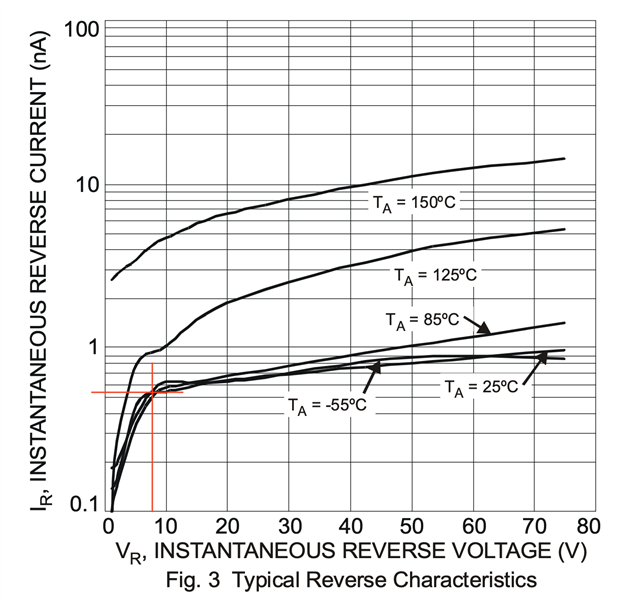
Leakage current = 0.55nA or 550pA which seems to be good to quite a high temperature

That would induce a voltage drop of 5.5uV across R2.  This would increase the opamp offset voltage from typical 8uV to 13.5uV (or max 50uV to 55.5uV.)  This is less than 1LSB of the ADC so seems like a reasonable approach to protect the Opamp and, possibly, the ADC.


But...


Those diodes, once they start conducting will push current into the voltage sources which are linear regulators and cannot sink current so may well end up toast - cheaper than the opamps - but also may just end up out of regulation and become over voltage suppliers themselves.  If I put a TVS or even a Zener on the regulator output that would just contribute additional and higher leakage current.


Could I put, say, a 1Mohm resistor between each diode and regulator to current limit and thus help with preventing the regulator going out of regulation but without affecting them under normal operating scenarios?  Also is it worth protecting the inverting input of the OpAmp with a resistor - with the architecture of this opamp not having internal protection diodes it may not add anything except additional noise?

image

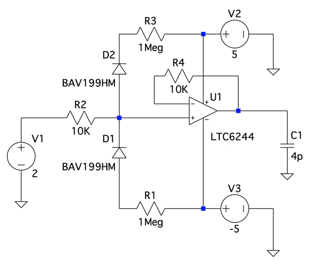
The choice of 10K for R2, with matching resistance for R4, is a tradeoff of current limiting into the opamp at 50V (0.25W) and additional noise (12.9nV/ √Hz )on a signal under normal circumstances.  With a 50V over voltage scenario, that's excessive voltage at the non-inverting input but only 5mA.  There will be things here that I'm unaware of so it may be that the better approach is just to go with current limiting and forget the diode protection; within my understanding it seems like a reasonable approach that won't have too much of an impact on the signal quality in relation to the ADC.

  • Sign in to reply
  • Cancel

Top Replies

  • jc2048
    jc2048 over 5 years ago +4
    What's the context in which you're trying to protect the input? The datasheet for the OPA192 says it's good to 4kV from the usual body model as per various JEDEC standards. It doesn't say how the protection…
  • dougw
    dougw over 5 years ago +3
    The most common ESD source for electronics is the human body which has a capacitance of about 200pf. If discharging this 200pf charged to 1000V to an uncharged 200nf capacitor should raise its voltage…
  • michaelkellett
    michaelkellett over 5 years ago in reply to Andrew J +2
    If you can it's a really good idea to put a cap from the input pin to ground - 100nF is a reasonable value if all you care about is EMC. In real life you often don't want a huge input shunt capacity. A…
Parents
  • dougw
    dougw over 5 years ago

    The most common ESD source for electronics is the human body which has a capacitance of about 200pf.

    If discharging this 200pf charged to 1000V to an uncharged 200nf capacitor should raise its voltage about 1V.

    I wouldn't worry about limiting the current or voltage to the supplies as long as they have reasonable capacitance.

    R1 and R3 also reduce protection of the op-amp input.

    You can put protection diodes (between output and input) on the regulators if you expect their outputs to get dragged around.

    The protection diodes on the input signal could also go to separate capacitors with bleed resistors if you are worried about it.

    I think there is a typo ... V3 is reversed polarity...

    • Cancel
    • Vote Up +3 Vote Down
    • Sign in to reply
    • Cancel
  • Andrew J
    Andrew J over 5 years ago in reply to dougw

    The supplies do have capacitance, and their are decoupling caps at the opamp input, which I haven't shown in the circuit but these capacitors are going to be charged up aren't they?  Wouldn't that then make the regulators current sinks if the diodes D1 or D2 start conducting?  I thought that would be an issue.  ESD is probably unlikely but I don't understand where it would go or where I might have an uncharged in-circuit capacitor.  I feel stupid for asking.


    I can see now how R1 and R3 cause a problem with clamping the voltage I must have not taken enough care with looking at the results image so they can go.  Thanks for making me look at that again!

    • Cancel
    • Vote Up 0 Vote Down
    • Sign in to reply
    • Cancel
Reply
  • Andrew J
    Andrew J over 5 years ago in reply to dougw

    The supplies do have capacitance, and their are decoupling caps at the opamp input, which I haven't shown in the circuit but these capacitors are going to be charged up aren't they?  Wouldn't that then make the regulators current sinks if the diodes D1 or D2 start conducting?  I thought that would be an issue.  ESD is probably unlikely but I don't understand where it would go or where I might have an uncharged in-circuit capacitor.  I feel stupid for asking.


    I can see now how R1 and R3 cause a problem with clamping the voltage I must have not taken enough care with looking at the results image so they can go.  Thanks for making me look at that again!

    • Cancel
    • Vote Up 0 Vote Down
    • Sign in to reply
    • Cancel
Children
  • dougw
    dougw over 5 years ago in reply to Andrew J

    I don't know what circuitry is in your regulators so I can't comment how they handle excess voltage on their output, but when a regulator has large capacitance on its output it is common to put a diode across the regulator to so that when power is turned off, the charge on the capacitor doesn't damage the regulator.

    • Cancel
    • Vote Up +1 Vote Down
    • Sign in to reply
    • Cancel
  • Andrew J
    Andrew J over 5 years ago in reply to dougw

    I do have diodes across the regulators as well.

    • Cancel
    • Vote Up +1 Vote Down
    • Sign in to reply
    • Cancel
element14 Community

element14 is the first online community specifically for engineers. Connect with your peers and get expert answers to your questions.

  • Members
  • Learn
  • Technologies
  • Challenges & Projects
  • Products
  • Store
  • About Us
  • Feedback & Support
  • FAQs
  • Terms of Use
  • Privacy Policy
  • Legal and Copyright Notices
  • Sitemap
  • Cookies

An Avnet Company © 2026 Premier Farnell Limited. All Rights Reserved.

Premier Farnell Ltd, registered in England and Wales (no 00876412), registered office: Farnell House, Forge Lane, Leeds LS12 2NE.

ICP 备案号 10220084.

Follow element14

  • X
  • Facebook
  • linkedin
  • YouTube